EP0989503A1 - Système de réseau avec acquisition de données à distance - Google Patents
Système de réseau avec acquisition de données à distance Download PDFInfo
- Publication number
- EP0989503A1 EP0989503A1 EP98118155A EP98118155A EP0989503A1 EP 0989503 A1 EP0989503 A1 EP 0989503A1 EP 98118155 A EP98118155 A EP 98118155A EP 98118155 A EP98118155 A EP 98118155A EP 0989503 A1 EP0989503 A1 EP 0989503A1
- Authority
- EP
- European Patent Office
- Prior art keywords
- sensor
- network system
- peripheral
- central computer
- computer
- Prior art date
- Legal status (The legal status is an assumption and is not a legal conclusion. Google has not performed a legal analysis and makes no representation as to the accuracy of the status listed.)
- Granted
Links
Images

Classifications
-
- H—ELECTRICITY
- H04—ELECTRIC COMMUNICATION TECHNIQUE
- H04M—TELEPHONIC COMMUNICATION
- H04M11/00—Telephonic communication systems specially adapted for combination with other electrical systems
- H04M11/04—Telephonic communication systems specially adapted for combination with other electrical systems with alarm systems, e.g. fire, police or burglar alarm systems
Definitions
- the present invention relates to a network system for exchanging information between a number of remote, peripheral computers and a central computer for remote data acquisition.
- the object of the present invention therefore is to provide a network system for reliable and quick remote data aquisition in order to ensure quick and reliable elimination of the malfunction or function of the system to be serviced.
- the invented network system for exchanging information comprises n ( n is an integer) peripheral computers or remote control units and a central computer for remote data acquisition, wherein each of the n peripheral computers comprises at least one communication interface having automatic data transfer function, a processor unit, a memory unit and an output/input interface, wherein the central computer comprises at least one communication interface having automatic data transfer function, a processor unit, a memory unit, a database unit and an output/input interface, the network system further comprising first coupling means for coupling the communication interface of the central computer to the telephone interface of any of the peripheral computers in order to exchange information between the central computer and said peripheral computer, sensor means for providing sensor information or data that relate to at least one characteristic to be detected or monitored, the sensor means comprising a sensor unit for generating the sensor information and a sensor interface, second coupling means for coupling the input/output interface of the at least one peripheral computer to the sensor interface of the sensor means in order to exchange information between the peripheral computer and
- the network system of the present invention comprises a communication interface in each of the remote, peripheral computers and also a communication interface in the central computer. Both communication interfaces have an automatic data transfer function, i.e. each communication is able to establish a connection upon a request or instruction being generated by a processor unit operated by software program. Further messaging of the user units also is initiated by computer program for automatic messaging by means of automatic data transfer function of the communication interface or I/O input/output interface. Consequently, the inventive network system has the advantage that a person is no longer required to distribute messages, information or instructions in the system and therefore the human source of error and delay in the system is avoided.
- the first coupling means is the Public Switched Telephone Network PSTN (digital or analog), leased line or some other network with data transfer capability, such as mobile communication networks (PCS 1900, DCS 1800, GSM 900, NMT, TACS) satellite communication network (Iridium SDMA, and Iridium AMPS), radio wave data transmission systems.
- PSTN Public Switched Telephone Network
- PCS 1900, DCS 1800, GSM 900, NMT, TACS satellite communication network
- Iridium SDMA, and Iridium AMPS radio wave data transmission systems.
- RAS Remote Access Server
- the input/output interface of the at least one peripheral computer and the corresponding sensor interface of the sensor means are serial interfaces, particularly RS232, RS485 or USB interfaces, and the second coupling means is then a wire or optical cable for connecting the interfaces in order to get a reliable and inexpensive connection from the sensor means to respective peripheral computer.
- the input/output-interface of the at least one peripheral computer and the corresponding sensor interface of the remote sensor means are radio transmission, electrical interfaces, infrared transmission interfaces.
- the user terminal of the at least one user unit is a mobile communication interface in order to obtain and improve the attain high mobility of the remote user units.
- the input/output interface or the communication interface of the central computer preferably transmit SMS short messages to the at least one user unit in order to enable us of widespread and handhelds expensive user units, for instance, electronic pagers, SCALL units and similar equipment.
- the input/output interface or the communication interface of the central computer can transmit a telefax message or an e-mail as information to the user unit.
- the central computer of the invention is able to initiate by means of its automatic data transfer function a data connection via its communication interface, the first coupling means and the communication interface of the at least one peripheral computer in order to transfer data between the central computer and the at least one peripheral computer.
- This feature enables the central computer to request and to fetch the remote data and information on demand.
- At least one peripheral computer can initiate a data connection by means of its automatic data transfer function via its communication interface, the first coupling means and the communication interface of the central computer in order to transfer data between the central computer and the at least one peripheral computer.
- a peripheral computer and the sensor means coupled to this remote peripheral computer by the second coupling means can be mounted in a mobile station or object, wherein the first coupling means for coupling the peripheral computer to the central computer is a communication network, particularly the GSM communication network.
- This configuration allows remote data acquisition, for instance, moving vehicle in order to provide a fleet management.
- the sensor means can comprise sensors for detecting temperature, pressure, flow of water, level, PH value and/or percentage of oxygen as technical characteristics in order to use the inventive network system as waste water management system. In the case of abnormalities the connection is established and corresponding SMS messages are sent to the user units.
- the sensor means can comprise sensors for monitoring the level and flow of water, recording authorised and unauthorised entrance and/or for surveying electricity consumption in order to use the network system of the invention as monitoring system of reservoirs of potable water or fresh water.
- the sensor means can comprise sensors for measuring of temperature, pressure, humidity, wind speed and/or rain fall in order to use the network system of the present invention as a weather monitoring station.
- the sensor means can comprise sensors for counting traffic and/or monitoring the conditions of the traffic environment in order to use the network system of the invention as traffic control and warning system.
- the sensor means can comprise sensors for measuring air pollution, smoke and/or the concentration of SO 2 or other harmful substances in order to use the network system of the invention as an air quality control system.
- the sensor means can comprise a sensor or voltage or current meter for detecting an electrical potential or voltage or current in a electrical unit or appliance as characteristic to be monitored in order to detect a malfunction or breakdown of the electrical appliance.
- the sensor means can comprise a seismic sensor for detecting seismic movements of the earth or an earthquake.
- the sensor means can comprise an identification or recognition sensor unit for identifying or recognising a person, an animal or an object which have a label thereon, identification means or card or have specific characteristics being readable by the identification or recognition sensor unit.
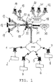
- Fig. 1 shows a overall view of a preferred implementation of the network system for remote data acquisition of the present invention.
- the shown implementation of the invention comprises a central computer 10, at least one but generally an number of n peripheral computers 1, 3, 5 and 7 installed at location remote from the central computer 10, first coupling means 9 that are able to couple or connect the peripheral computers 1, 3, 5 and 7 to the central computer 10 in order to establish a connection between the central computer 10 and the peripheral computers 1, 3, 5 and 7 for information exchange and remote data acquisition, at least one but generally a number or several user units 11, 12, 13 being generally at a location remote from the central computer 10, third coupling means 16 for coupling or connecting the user units 11, 12, 13 to the central computer 10 and at least one but generally a number of n sensor means 2, 4, 6 and 8 that are coupled to the corresponding peripheral computers 1, 3, 5 and 7, respectively, by corresponding second coupling means 47.
- the peripheral computers 1, 3, 5 and 7 operate independently of each other.
- Each of the peripheral computers 1, 3, 5 and 7 comprises for instance an industrial computer on the basis of an Intel 386 or 486 of Pentium CPU with input/output units and boards, memory units particular a FLASH memory unit and a GSM modem as communication interface 43 (please refer to figure 2), for instance, a WAVECOM TYPE: WM 01-G900 modem on the basis of a AT Hayes instruction set and AT GSM instruction set which is able to initiate or start automatically or establish a connection under control of the processor unit of the respective peripheral computer 1, 3, 5 and 7. All interfaces and units of the whole peripheral computer are mounted in an robust housing. Further, depending on the specific application, the power supply of the peripheral computer installed at remote site is provided by, for instance, a battery or by a solar cell panel unit, if the remote site does not have connection to the mains network.
- Each of the n peripheral computers 1, 3, 5 and 7 further comprises an output/input interface 41 that enables to establish a connection to the respective sensor means 2, 4, 6 and 8 each of which is assigned to the number of peripheral computers 1, 3, 5 and 7, respectively.
- Each of the peripheral computers therefore comprises a control function of the corresponding sensor means and a processing function for processing the remote data or information or signals provided by the sensor means and data transfer function for establishing the data connection to the central computer 10 in order to report or send the data of the sensor means 2 or the processed data or information to the central computer 10.
- Each of the sensor means 2, 4, 6 and 8 is connected to its respective and corresponding one of the number of peripheral computers 1, 3, 5 and 7 as shown in figure 1.
- the sensor means 2 is coupled to the peripheral computer 1
- the sensor means 4 is coupled to the peripheral computer 3
- the sensor means 6 is coupled to the peripheral computer 5
- the sensor means 8 is coupled to the peripheral computer 7, wherein the coupling of each pair of sensor means and peripheral computer is provided by the second coupling means that, for instance, is a wire-cable, a radio wave transmission line, an infrared or optical transmission line or a GSM telephone transmission.
- Each sensor means 2, 4, 6 and 8 comprises a sensor unit 21 and a sensor interface 22 that is connected to the sensor unit 21.
- the sensor unit 21 comprises the specific sensors, sensor element and electrical circuits for detecting a specific physical or technical characteristic of the environment, site or device or appliance where the sensor means is situated in order to detect the specific characteristic and to generate remote information and data as intended.
- the sensor interface 22 receives the detected information from the sensor unit and generally further processes and outputs the received information on the second coupling means 47 in order to transfer the information and data to the output/input interface 41 of the peripheral computer 1 that is assigned according to figure 2 showing a selected specific route of the network system in figure 1.
- This specific route extends from the sensor means 2 where remote data and information originates, via the peripheral computer 1, the communication network 9, the central computer 10, the SMS short message service 16 to the user unit 11 being remote from the central computer 10.
- the detected data or information in the sensor means 2 is serially transferred by the second coupling means 47 to the peripheral computer 1. Therefore the sensor interface 22 and also the input/output interface 41 of the peripheral computer 1 are serial interfaces that meet, for instance, the RS 232, RS 485 or USB (Universal Serial Bus) standards.
- the second coupling means 47 is, therefore, a wire and optical cable for serial data transmission.
- the central computer 10 is for instance placed at the headquarters of the network system administration and management and comprises at least one processor unit, database for mass storage, a memory unit, an input/output interface 45 and a communication interface 44.
- the central computer 10 is adapted to operate as system network server and comprises one or several Pentium II CPU processor units 32 clocked with 300 MHz, a memory unit with 256 MB RAM, a SCSI harddisc 3 x 4GB as database mass storage 30, a dual port SCSI controller, an ethernet network adapter 10/100 for connection to a LAN (Local Area Network) to which the central computer 10 is connected, a 17 inch monitor 33 and additional peripheral units like compact disc player, keyboards, mouse etc..
- LAN Local Area Network
- the communication interface 44 of the central computer comprises one or more GSM modems, for instance on the basis of a WAVECOM TYPE: WM 01-G900 modem that preferably supports the regular AT Hayes instruction set and the AT GSM instruction set for control by the processor unit of the central computer 10.
- the communication interface 44 of the central computer 10 can in alternative be implemented by a RAS server (Remote Access Server) 31, gateways or routers in order to establish a point to point connection via the communication network to the respective peripheral computers 1, 3, 5 and 7.
- the software protocol for establishing and maintaining a connection between the communication interface 43, GSM modem, of each of the peripheral computers 1, 3, 5 and 7 and the communication interface 44 of the central computer 10 in point to point connection over the GSM network 9 is carried out on the basis of the well known TCP/IP communication protocol.
- operating system for instance, the Microsoft WINDOWS NT operating system is installed on the central computer 10.
- SQL software program for control of database storage and Exchange communication software for sending e-mails and faxes to user units 14 and 15 are installed on the central computer 10.
- a controlling, administration and application program being adapted to the specific application of the inventive network system, for instance, as maintenance system, alarm system, monitoring system, etc., is software implemented in the central computer 10.
- central computer 10 comprises the specific communication software for driving and controlling the communication interface 44 and the input/output interfaces 45 in order to establish and maintain the connection between each of the peripheral computers 1, 3, 5 and 7 and the central computer 10 and each of the user units 11, 12, 13, 14 and 15 and the central computer 10.
- the input/output interface 45 is a SMS short message service which output messages, instructions or information data to each of the user units 11 to 15 or to a group out of the user units via the third coupling means 16 being realised as SMS short message service network.
- the input/output interface 45 of the central computer 10 is adapted to send e-mails and telefax messages and information to a remote administrator PC unit 14 and a remote telefax receiving unit 15, respectively, which units are also user units in the sense of the present invention.
- the connection between the remote administrator PC unit 14 and the remote telefax unit 15 and the central computer 10 is, for instance, accomplished by a e-mail/telefax network 17 that, for instance, is the usual public telephone network.
- the input/output interface 45 and/or the communication interface 44 of the central computer 10 are able to establish a data communication between a number of further administrator PC units 50, 51 and 52 via a web and network application 18 in order to establish or to implement a remote control function of the central computer 10 by an system administrator or several system administrators or a system supervisor.
- Each of the user units 11, 12 and 13 is adapted to communicate over the SMS short message service network 16 with the central computer 10.
- Each of the user units 11, 12 and 13 therefore comprises a user terminal 46 in order to establish and maintain a connection between each of the user units 11, 12 and 13 and the central computer 10 over the SMS short message network 16, if required.
- the sensor unit 21 of the sensor means 2 detects a physical or technical characteristic and outputs information or data from the sensor interface 22 over the second coupling means 47 that, in this case, is a wire and optical cable for serial data communication, to the output/input interface 41 of the peripheral computer 1.
- the peripheral computer 1 receives and processes the data from the sensor means 2.
- the peripheral computer 1 for instance, compares the sensor data with a predetermined value or information stored in the memory unit of the peripheral computer 1. If the sensor data have a value exceeding the predetermined value, the peripheral computer 1, specifically its processor unit, generates information or data that, in the following, are referred to as remote alarm data or remote monitor data in accordance to its running application program. Accordingly, the peripheral computer 1 or remote control unit is able to monitor the condition or status of the physical or technical characteristic to be monitored.
- the communication program of the peripheral computer 1 then, in the case of alarm data, triggers the communication interface 43 of the peripheral computer 1 in order to establish a telephone connection between the peripheral computer 1 and the central computer 10 for transferring the alarm data or information, or generally, remote data. If the communication interface 43 succeeds in establishing a telephone communication with the central computer 10 on the basis of the TCP/IP or som other communication protocol, which means, that the central computer 10 has answered and is prepared to receive the remote data or alarm data, then the peripheral computer 1 transmits the alarm data over the GSM telephone network to the communication interface 44 of the central computer 10.
- the running application program in the central computer 10 processes the alarm data or remote data. and selects one user unit, 11 in figure 2, or a group of user units from the user units 11 to 15 on the basis of data and information stored in the database 30 of the central computer 10.
- the central computer 10 particularly its processor unit, triggers the communication program of the central computer 10 in order to establish a SMS short message service connection between the input/output interface 45 of the central computer 10, for instance an SMS short message service interface or communication interface, and the user terminal 46 of the user unit 11. If the central computer succeeds in establishing this connection, the central computer 10 then outputs a SMS short message to the user unit 11 over the SMS network 16.
- the user unit 11 indicates receipt of a SMS short message to the user of the user unit 11 and indicates the SMS message itself on its display.
- the central computer 10 is able to distribute remote data or information received from each of the peripheral computers 1, 3, 5 and 7 to each of the remote user units 11, 12 and 13. For instance the central computer 10 is able to send information or remote data received from the peripheral computer 5 to the user unit 13 if the central computer 10 has selected the user unit 13 that has to be informed in accordance to the application program.
- the sensor means 2 and the peripheral computer 1 is situated at a remote location with regard to the central computer 10 of the maintenance system, for instance, at or in an electrical appliance, the power station of a plant.
- a task of the maintenance system consists of recognising a malfunction or failure of the power station, in ensuring to eliminate the malfunction and in resuming normal functioning of the power station as soon as possible.
- the sensor unit 21 of the sensor means 2 is a current meter or a voltage meter connected to a Schmidt trigger and a electronic analogue/digital converter that converts the analogue output signal of the Schmitt trigger into a digital valve which is output by the serial sensor interface 22 over the serial wire and optical cable 47 to the input/output interface 41 of the peripheral computer 1. If the power current or voltage of the power station falls below a certain value a malfunction of the plant would result, if no countermeasures would be taken. If the malfunction case arises the Schmidt trigger of the sensor unit alters its output signal, which is a strong indication of malfunction and the analogue/digital converter converts the output of the Schmidt trigger into digital data that are read by the peripheral computer 1.
- the application program of the peripheral computer 1 recognises on the basis of the changing remote data from the sensor means 2 that a malfunction of the power station has occurred and, therefore, the peripheral computer 1 generates alarm data that indicate the malfunction.
- the alarm data are send over the GSM communication network 9 to the central computer 10 after establishing a corresponding GSM data connection between the peripheral computer 1 and the central computer 10.
- the central computer After receiving the alarm data, the central computer executes corresponding procedure that is a part of the application program in order to select one of the user units 11 to 13. For instance, the selecting procedure at first searches for a user unit 11, 12, 13 being active in the moment at the location nearest to the source of malfunction. This searching is made in the database 30, where a table of all numbers, characteristics and statues of each of the user units 11 to 13 is stored in the form of digital data. For instance, the central computer 10 does find the user unit 13 not to be activated and that only the user units 11 and 12 are activated. Further the condition of the user unit 12 is found to be occupied which means that this user unit 12 in the moment is already involved in a maintenance procedure and, therefore, cannot be used.
- the central computer 10 therefore, sends a corresponding SMS message over the SMS network 16 to the user unit 11.
- the unit 11 then indicates receipt of the SMS message and the user or the maintenance personal using this user unit 11 therefore is able to recognise the malfunction and to eliminate the malfunction immediately.
Landscapes
- Engineering & Computer Science (AREA)
- Signal Processing (AREA)
- Measuring Pulse, Heart Rate, Blood Pressure Or Blood Flow (AREA)
- Arrangements For Transmission Of Measured Signals (AREA)
- Computer And Data Communications (AREA)
- Telephonic Communication Services (AREA)
- Communication Control (AREA)
- Selective Calling Equipment (AREA)
Priority Applications (5)
| Application Number | Priority Date | Filing Date | Title |
|---|---|---|---|
| AT98118155T ATE204395T1 (de) | 1998-09-24 | 1998-09-24 | Netzwerksystem mit ferndatenerfassung |
| EP98118155A EP0989503B1 (fr) | 1998-09-24 | 1998-09-24 | Système de réseau avec acquisition de données à distance |
| DE69801370T DE69801370T2 (de) | 1998-09-24 | 1998-09-24 | Netzwerksystem mit Ferndatenerfassung |
| AU59957/99A AU5995799A (en) | 1998-09-24 | 1999-09-22 | Network system with remote data acquisition |
| PCT/IB1999/001713 WO2000018175A2 (fr) | 1998-09-24 | 1999-09-22 | Systeme de reseau avec acquisition de donnees a distance |
Applications Claiming Priority (1)
| Application Number | Priority Date | Filing Date | Title |
|---|---|---|---|
| EP98118155A EP0989503B1 (fr) | 1998-09-24 | 1998-09-24 | Système de réseau avec acquisition de données à distance |
Publications (2)
| Publication Number | Publication Date |
|---|---|
| EP0989503A1 true EP0989503A1 (fr) | 2000-03-29 |
| EP0989503B1 EP0989503B1 (fr) | 2001-08-16 |
Family
ID=8232685
Family Applications (1)
| Application Number | Title | Priority Date | Filing Date |
|---|---|---|---|
| EP98118155A Expired - Lifetime EP0989503B1 (fr) | 1998-09-24 | 1998-09-24 | Système de réseau avec acquisition de données à distance |
Country Status (5)
| Country | Link |
|---|---|
| EP (1) | EP0989503B1 (fr) |
| AT (1) | ATE204395T1 (fr) |
| AU (1) | AU5995799A (fr) |
| DE (1) | DE69801370T2 (fr) |
| WO (1) | WO2000018175A2 (fr) |
Cited By (9)
| Publication number | Priority date | Publication date | Assignee | Title |
|---|---|---|---|---|
| FR2811177A1 (fr) * | 2000-06-29 | 2002-01-04 | Sate Sarl | Procede de surveillance a distance de sites ou de personnes et dispositif le mettant en oeuvre |
| FR2815744A1 (fr) * | 2000-10-19 | 2002-04-26 | Sagem | Dispositif de gestion d'application d'administration et procede associe |
| EP1220512A2 (fr) * | 2000-10-02 | 2002-07-03 | Omron Corporation | Réseau de communications et systeme de négotiation |
| WO2003001469A1 (fr) * | 2001-06-26 | 2003-01-03 | Intamac Systems Limited | Systeme de protection de propriete |
| WO2003010731A1 (fr) * | 2001-07-23 | 2003-02-06 | Edwards Systems Technology, Incorporated | Modem communicateur |
| US7155507B2 (en) | 2000-03-25 | 2006-12-26 | Nippon Telegraph And Telephone Corporation | Method and system for providing environmental information on network |
| CN102176279A (zh) * | 2011-01-28 | 2011-09-07 | 太原理工大学 | 一种传感器信号双网无线传输装置 |
| CN105763654A (zh) * | 2016-05-12 | 2016-07-13 | 孙文兵 | 一种直饮水机远程控制系统 |
| CN112383605A (zh) * | 2020-11-09 | 2021-02-19 | 广西信路威科技发展有限公司 | 高速公路监控设备远程维保系统和维保方法 |
Families Citing this family (1)
| Publication number | Priority date | Publication date | Assignee | Title |
|---|---|---|---|---|
| EP3373568A3 (fr) | 2000-05-23 | 2018-11-07 | IoT IP GmbH | Communicateur programmable |
Citations (9)
| Publication number | Priority date | Publication date | Assignee | Title |
|---|---|---|---|---|
| US3881094A (en) * | 1973-07-05 | 1975-04-29 | Velcon Filters | Signal for evaluating sailboat performance |
| US4390951A (en) * | 1979-09-07 | 1983-06-28 | Thomson-Csf | Apparatus for monitoring road traffic to control an associated signaling system |
| WO1987003116A1 (fr) * | 1985-11-19 | 1987-05-21 | Santiago Data Systems, Inc. | Systeme d'acquisition de donnees pour foire commerciale |
| EP0425330A1 (fr) * | 1989-10-24 | 1991-05-02 | Pesage Gestion Communication S.A.R.L. | Système de collecte sur un site central de données d'une pluralité d'installations |
| US5061916A (en) * | 1990-05-29 | 1991-10-29 | Barber-Colman Company | Event driven remote graphical reporting of building automation system parameters |
| US5396246A (en) * | 1992-10-13 | 1995-03-07 | Institut Francais Du Petrole | Device for the digital combination of signals |
| US5561610A (en) * | 1994-06-30 | 1996-10-01 | Caterpillar Inc. | Method and apparatus for indicating a fault condition |
| US5717379A (en) * | 1995-04-10 | 1998-02-10 | Alcatel N.V. | Remote monitoring system |
| US5745849A (en) * | 1996-02-09 | 1998-04-28 | Digital Monitoring Products, Inc. | Combination cordless telephone and premise-monitoring alarm system |
-
1998
- 1998-09-24 EP EP98118155A patent/EP0989503B1/fr not_active Expired - Lifetime
- 1998-09-24 AT AT98118155T patent/ATE204395T1/de not_active IP Right Cessation
- 1998-09-24 DE DE69801370T patent/DE69801370T2/de not_active Expired - Lifetime
-
1999
- 1999-09-22 WO PCT/IB1999/001713 patent/WO2000018175A2/fr unknown
- 1999-09-22 AU AU59957/99A patent/AU5995799A/en not_active Abandoned
Patent Citations (9)
| Publication number | Priority date | Publication date | Assignee | Title |
|---|---|---|---|---|
| US3881094A (en) * | 1973-07-05 | 1975-04-29 | Velcon Filters | Signal for evaluating sailboat performance |
| US4390951A (en) * | 1979-09-07 | 1983-06-28 | Thomson-Csf | Apparatus for monitoring road traffic to control an associated signaling system |
| WO1987003116A1 (fr) * | 1985-11-19 | 1987-05-21 | Santiago Data Systems, Inc. | Systeme d'acquisition de donnees pour foire commerciale |
| EP0425330A1 (fr) * | 1989-10-24 | 1991-05-02 | Pesage Gestion Communication S.A.R.L. | Système de collecte sur un site central de données d'une pluralité d'installations |
| US5061916A (en) * | 1990-05-29 | 1991-10-29 | Barber-Colman Company | Event driven remote graphical reporting of building automation system parameters |
| US5396246A (en) * | 1992-10-13 | 1995-03-07 | Institut Francais Du Petrole | Device for the digital combination of signals |
| US5561610A (en) * | 1994-06-30 | 1996-10-01 | Caterpillar Inc. | Method and apparatus for indicating a fault condition |
| US5717379A (en) * | 1995-04-10 | 1998-02-10 | Alcatel N.V. | Remote monitoring system |
| US5745849A (en) * | 1996-02-09 | 1998-04-28 | Digital Monitoring Products, Inc. | Combination cordless telephone and premise-monitoring alarm system |
Non-Patent Citations (1)
| Title |
|---|
| ALBERT K: "ON-LINE ALARM FOR SYSTEM FAULTS", ENGINEERING AND AUTOMATION, vol. 18, no. 5, September 1996 (1996-09-01), pages 6/7, XP000643830 * |
Cited By (14)
| Publication number | Priority date | Publication date | Assignee | Title |
|---|---|---|---|---|
| US7155507B2 (en) | 2000-03-25 | 2006-12-26 | Nippon Telegraph And Telephone Corporation | Method and system for providing environmental information on network |
| FR2811177A1 (fr) * | 2000-06-29 | 2002-01-04 | Sate Sarl | Procede de surveillance a distance de sites ou de personnes et dispositif le mettant en oeuvre |
| EP1220512A3 (fr) * | 2000-10-02 | 2004-01-28 | Omron Corporation | Réseau de communications et systeme de négotiation |
| EP1220512A2 (fr) * | 2000-10-02 | 2002-07-03 | Omron Corporation | Réseau de communications et systeme de négotiation |
| US7149696B2 (en) | 2000-10-02 | 2006-12-12 | Omron Corporation | System and method for accepting information from information providers, mediating the received information, and providing mediated information to information beneficiaries |
| FR2815744A1 (fr) * | 2000-10-19 | 2002-04-26 | Sagem | Dispositif de gestion d'application d'administration et procede associe |
| WO2003001469A1 (fr) * | 2001-06-26 | 2003-01-03 | Intamac Systems Limited | Systeme de protection de propriete |
| WO2003010731A1 (fr) * | 2001-07-23 | 2003-02-06 | Edwards Systems Technology, Incorporated | Modem communicateur |
| GB2385743A (en) * | 2001-07-23 | 2003-08-27 | Edwards Systems Technolgy Inc | Modem communicator |
| GB2385743B (en) * | 2001-07-23 | 2004-06-30 | Edwards Systems Technolgy Inc | Modem communicator |
| CN102176279A (zh) * | 2011-01-28 | 2011-09-07 | 太原理工大学 | 一种传感器信号双网无线传输装置 |
| CN102176279B (zh) * | 2011-01-28 | 2012-12-26 | 太原理工大学 | 一种传感器信号双网无线传输装置 |
| CN105763654A (zh) * | 2016-05-12 | 2016-07-13 | 孙文兵 | 一种直饮水机远程控制系统 |
| CN112383605A (zh) * | 2020-11-09 | 2021-02-19 | 广西信路威科技发展有限公司 | 高速公路监控设备远程维保系统和维保方法 |
Also Published As
| Publication number | Publication date |
|---|---|
| AU5995799A (en) | 2000-04-10 |
| WO2000018175A3 (fr) | 2000-05-25 |
| DE69801370T2 (de) | 2002-05-23 |
| WO2000018175A2 (fr) | 2000-03-30 |
| ATE204395T1 (de) | 2001-09-15 |
| DE69801370D1 (de) | 2001-09-20 |
| EP0989503B1 (fr) | 2001-08-16 |
Similar Documents
| Publication | Publication Date | Title |
|---|---|---|
| US6553336B1 (en) | Smart remote monitoring system and method | |
| CN104091413B (zh) | 一种防汛雨水情自动监测方法 | |
| EP0989503B1 (fr) | Système de réseau avec acquisition de données à distance | |
| EP0520769A2 (fr) | Gestionnaire de système d'ordinateur | |
| EP1102433A3 (fr) | Procédé et dispositif de détection de défaillances | |
| US20070276626A1 (en) | System and apparatus for remote monitoring of conditions in locations undergoing water damage restoration | |
| CN209283265U (zh) | 一种可无线联网水面测流系统 | |
| CN109405896A (zh) | 设备运行状态的检测系统以及方法 | |
| CN104103152B (zh) | 一种防汛雨水情自动监测方法 | |
| CN108198400A (zh) | 一种北斗移动智能终端及其省电工作方法 | |
| CN209166522U (zh) | 设备运行状态的检测系统 | |
| US6727813B2 (en) | Alarm notifying device and computer program | |
| WO2005036493A1 (fr) | Utilisation par et sans fil d'un systeme de lecture de compteur distant | |
| US20020041238A1 (en) | Pager based monitoring | |
| CN208572280U (zh) | 一种船舶监控管理系统 | |
| CN111157586A (zh) | 一种水质监测方法、装置及系统 | |
| JP3813064B2 (ja) | 水道施設の設備稼働状態監視システム | |
| CN213958235U (zh) | 一种机房漏水状态报警系统 | |
| KR970002768B1 (ko) | 가입자 선로를 이용한 실시간 상황 감시장치 | |
| JP4538957B2 (ja) | 網制御装置 | |
| CN212649507U (zh) | 一种电网线塔在线监测系统 | |
| JPH1030271A (ja) | マンホール形式ポンプ場の汚水監視装置 | |
| CN106643966A (zh) | 一种简易型水位采集报警系统及其工作机制 | |
| EP0715393B1 (fr) | Système étendu pour la détection de pollution de l'environnement, en particulier la pollution atmosphérique | |
| KR930006418B1 (ko) | 무선 원격 검침시스템 및 그 제어방법 |
Legal Events
| Date | Code | Title | Description |
|---|---|---|---|
| PUAI | Public reference made under article 153(3) epc to a published international application that has entered the european phase |
Free format text: ORIGINAL CODE: 0009012 |
|
| 17P | Request for examination filed |
Effective date: 19990922 |
|
| AK | Designated contracting states |
Kind code of ref document: A1 Designated state(s): AT DE GB IT |
|
| AX | Request for extension of the european patent |
Free format text: AL;LT;LV;MK;RO;SI |
|
| AKX | Designation fees paid |
Free format text: AT DE GB IT |
|
| GRAG | Despatch of communication of intention to grant |
Free format text: ORIGINAL CODE: EPIDOS AGRA |
|
| GRAG | Despatch of communication of intention to grant |
Free format text: ORIGINAL CODE: EPIDOS AGRA |
|
| GRAH | Despatch of communication of intention to grant a patent |
Free format text: ORIGINAL CODE: EPIDOS IGRA |
|
| GRAH | Despatch of communication of intention to grant a patent |
Free format text: ORIGINAL CODE: EPIDOS IGRA |
|
| GRAA | (expected) grant |
Free format text: ORIGINAL CODE: 0009210 |
|
| AK | Designated contracting states |
Kind code of ref document: B1 Designated state(s): AT DE GB IT |
|
| REF | Corresponds to: |
Ref document number: 204395 Country of ref document: AT Date of ref document: 20010915 Kind code of ref document: T |
|
| REF | Corresponds to: |
Ref document number: 69801370 Country of ref document: DE Date of ref document: 20010920 |
|
| REG | Reference to a national code |
Ref country code: GB Ref legal event code: IF02 |
|
| PLBE | No opposition filed within time limit |
Free format text: ORIGINAL CODE: 0009261 |
|
| STAA | Information on the status of an ep patent application or granted ep patent |
Free format text: STATUS: NO OPPOSITION FILED WITHIN TIME LIMIT |
|
| 26N | No opposition filed | ||
| PGFP | Annual fee paid to national office [announced via postgrant information from national office to epo] |
Ref country code: GB Payment date: 20090922 Year of fee payment: 12 Ref country code: AT Payment date: 20090921 Year of fee payment: 12 |
|
| PGFP | Annual fee paid to national office [announced via postgrant information from national office to epo] |
Ref country code: DE Payment date: 20090930 Year of fee payment: 12 |
|
| PGFP | Annual fee paid to national office [announced via postgrant information from national office to epo] |
Ref country code: IT Payment date: 20090923 Year of fee payment: 12 |
|
| GBPC | Gb: european patent ceased through non-payment of renewal fee |
Effective date: 20100924 |
|
| PG25 | Lapsed in a contracting state [announced via postgrant information from national office to epo] |
Ref country code: IT Free format text: LAPSE BECAUSE OF NON-PAYMENT OF DUE FEES Effective date: 20100924 |
|
| REG | Reference to a national code |
Ref country code: DE Ref legal event code: R119 Ref document number: 69801370 Country of ref document: DE Effective date: 20110401 |
|
| PG25 | Lapsed in a contracting state [announced via postgrant information from national office to epo] |
Ref country code: DE Free format text: LAPSE BECAUSE OF NON-PAYMENT OF DUE FEES Effective date: 20110401 |
|
| PG25 | Lapsed in a contracting state [announced via postgrant information from national office to epo] |
Ref country code: GB Free format text: LAPSE BECAUSE OF NON-PAYMENT OF DUE FEES Effective date: 20100924 Ref country code: AT Free format text: LAPSE BECAUSE OF NON-PAYMENT OF DUE FEES Effective date: 20100924 |