EP0988978B1 - Cleaning of orifices in an ink jet printing apparatus - Google Patents
Cleaning of orifices in an ink jet printing apparatus Download PDFInfo
- Publication number
- EP0988978B1 EP0988978B1 EP99202984A EP99202984A EP0988978B1 EP 0988978 B1 EP0988978 B1 EP 0988978B1 EP 99202984 A EP99202984 A EP 99202984A EP 99202984 A EP99202984 A EP 99202984A EP 0988978 B1 EP0988978 B1 EP 0988978B1
- Authority
- EP
- European Patent Office
- Prior art keywords
- ink jet
- cleaning
- roller
- orifices
- cleaning fluid
- Prior art date
- Legal status (The legal status is an assumption and is not a legal conclusion. Google has not performed a legal analysis and makes no representation as to the accuracy of the status listed.)
- Expired - Lifetime
Links
Images


Classifications
-
- B—PERFORMING OPERATIONS; TRANSPORTING
- B41—PRINTING; LINING MACHINES; TYPEWRITERS; STAMPS
- B41J—TYPEWRITERS; SELECTIVE PRINTING MECHANISMS, i.e. MECHANISMS PRINTING OTHERWISE THAN FROM A FORME; CORRECTION OF TYPOGRAPHICAL ERRORS
- B41J2/00—Typewriters or selective printing mechanisms characterised by the printing or marking process for which they are designed
- B41J2/005—Typewriters or selective printing mechanisms characterised by the printing or marking process for which they are designed characterised by bringing liquid or particles selectively into contact with a printing material
- B41J2/01—Ink jet
- B41J2/135—Nozzles
- B41J2/165—Preventing or detecting of nozzle clogging, e.g. cleaning, capping or moistening for nozzles
- B41J2/16517—Cleaning of print head nozzles
- B41J2/16552—Cleaning of print head nozzles using cleaning fluids
-
- B—PERFORMING OPERATIONS; TRANSPORTING
- B41—PRINTING; LINING MACHINES; TYPEWRITERS; STAMPS
- B41J—TYPEWRITERS; SELECTIVE PRINTING MECHANISMS, i.e. MECHANISMS PRINTING OTHERWISE THAN FROM A FORME; CORRECTION OF TYPOGRAPHICAL ERRORS
- B41J2/00—Typewriters or selective printing mechanisms characterised by the printing or marking process for which they are designed
- B41J2/005—Typewriters or selective printing mechanisms characterised by the printing or marking process for which they are designed characterised by bringing liquid or particles selectively into contact with a printing material
- B41J2/01—Ink jet
- B41J2/17—Ink jet characterised by ink handling
- B41J2/18—Ink recirculation systems
- B41J2/185—Ink-collectors; Ink-catchers
Definitions
- This invention relates to ink jet print head cleaning apparatus and more particularly relates to cleaning apparatus for cleaning multiple orifices belonging to such a print head.
- ink jet printing apparatus Many different types of digitally controlled printing systems of ink jet printing apparatus are presently being used. These ink jet printers use a variety of actuation mechanisms, a variety of marking materials, and a variety of recording media. For home applications, digital ink jet printing apparatus is the printing system of choice because low hardware cost make the printer affordable to every one. Another application for digital ink jet printing uses large format printers. It is a further requirement that these large format printers provide low cost copies with an ever improving quality. Ink jet printing technology is the first choice in today's art. Thus, there is a need for improved ways to make digitally controlled graphic arts media, such as billboards, large displays, and home photos for example, so that quality color images may be made at a high-speed and low cost, using standard or special paper.
- digitally controlled graphic arts media such as billboards, large displays, and home photos for example
- Ink jet printing has become recognized as a prominent contender in the digitally controlled, electronic printing arena because of its nonimpact, low-noise characteristics, its use of papers from plain paper to specialized high gloss papers and its avoidance of toner transfers and fixing.
- Ink jet printing mechanisms can be categorized as either continuous ink jet or droplet on demand ink jet. Continuous ink jet printing dates back to at least 1929. See U.S. Patent 1,941,001 to Hansell.
- U.S. Patent 3,416,153 issued to Hertz et al. in 1966, discloses a method of achieving variable optical density of printed spots in continuous ink jet printing using the electrostatic dispersion of a charged droplet stream to modulate the number of droplets which pass through a small orifice. This technique is used in ink jet printers manufactured by Iris.
- US Patent 4,346,387 issued to Hertz in 1982 discloses a method and apparatus for controlling the electric charge on droplets formed by the breaking up of a pressurized liquid stream at a droplet formation point located within the electric field having an electric potential gradient. Droplet formation is effected at a point in the field corresponding to the desired predetermined charge to be placed on the droplets at the point of their formation. In addition to charging tunnels, deflection plates are used to actually deflect droplets.
- Conventional continuous ink jet utilizes electrostatic charging tunnels that are placed close to the point where the droplets are formed in a stream. In this manner individual droplets may be charged. The charged droplets may be deflected downstream by the presence of deflector plates that have a large potential difference between them. A gutter (sometimes referred to as a "catcher") may be used to intercept the charged droplets, while the uncharged droplets are free to strike the recording medium. If there is no electric field present or if the break off point from the droplet is sufficiently far from the electric field (even if a portion of the stream before droplets break off is in the presence of an electric field), then charging will not occur.
- the on demand type ink jet printers are covered by hundreds of patents and describe two techniques for droplet formation.
- a pressurization actuator is used to produce the ink jet droplet.
- the two types of actuators are heat and piezo materials.
- the heater at a convenient location heats ink and a quantity will phase change into a gaseous steam bubble and raise the internal ink pressure sufficiently for an ink droplet to be expelled to a suitable receiver.
- the piezo ink actuator incorporates a piezo material. It is said to possess piezo electric properties if an electric charge is produced when a mechanical stress is applied.
- piezoelectric ceramics are: lead zirconate titanate, barium titanate, lead titanate, and lead metaniobate.
- a ferroelectric ceramic is machined to produce ink chambers.
- the chamber is water proofed by gold plating and becomes a conductor to apply the charge and cause the piezo "motor effect". This "motor effect" causes the ink cavity to shrink, raise the internal pressure, and generate an ink droplet.
- Inks for high speed jet droplet printers must have a number of special characteristics. Typically, water-based inks have been used because of their conductivity and viscosity range. Thus, for use in a jet droplet printer the ink must be electrically conductive, having a resistivity below about 5000 ohm-cm and preferably below about 500 ohm-cm. For good flow through small orifices water-based inks generally have a viscosity in the range between about 1 to 15 centipoise at 25 degree C.
- the ink must be stable over a long period of time, compatible with the materials comprising the orifice plate and ink manifold, free of living organisms, and functional after printing.
- the required functional characteristics after printing are: smear resistance after printing, fast drying on paper, and waterproof when dry. Examples of different types of water-based jet droplet printing inks are found in U.S. Patents 3,903,034; 3,889,269; 3,870,528; 3,846,141; 3,776,642; and 3,705,043.
- the ink also has to incorporate a nondrying characteristic in the jet cavity so that the drying of ink in the cavity is hindered or slowed to such a degree that through occasional spitting of ink droplets the cavities can be kept open.
- the addition of glycol will facilitate the free flow of ink through the ink jet.
- Ink jet printing apparatus typically includes an ink jet print head that is exposed to the various environment where ink jet printing is utilized. The orifices are exposed to all kinds of air born particles. Particulate debris accumulates on the surfaces, forming around the orifices. The ink will combine with such particulate debris to form an interference burr to block the orifice or cause through an altered surface wetting to inhibit a proper formation of the ink droplet.
- That particulate debris has to be cleaned from the orifice to restore proper droplet formation.
- This cleaning commonly is achieved by wiping, spraying, vacuum suction, and/or spitting of ink through the orifice.
- the wiping as disclosed in GB-A-2 319 221 is the most common application.
- Inks used in ink jet printers can be said to have the following problems:
- a cleaning apparatus for cleaning multiple orifices belonging to the print head, comprising:
- An advantage of the present invention is that rapid cleaning of orifices is accomplished in such a short time.
- Another advantage of the present invention is that cleaning fluid on the roller is replenished at a predetermined rate and removes waste ink and particulate debris permanently from the ink jet print head.
- Yet another advantage of this invention is that the cleaning fluid on the roller can have a substantial thickness thereby minimizing the requirements for mechanical tolerances.
- Still another advantage of this cleaning technique is that with no mechanical rubbing, the wear of the delicate orifice plate is eliminated or greatly reduced. The replacement of the ink jet head will be less frequent and more of the orifices will stay functional to result in a higher image quality.
- Another advantage is that individual inks can be cleaned by selecting the rotation rate of the roller to change the turbulence or agitation rate. In this way, the speed of the roller can be selected to match the cleaning needs of a particular ink. In other words, red , green, and blue inks in the same cartridge can have different roller speeds.
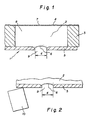
- FIG.. 1 shows a prior art cross sectional view of an ink jet print head 1.
- Orifices defining structures such as the depicted outlet plate 5 includes orifice 9 having a diameter "d" and can be manufactured by electro-forming or sheet metal fabrication methods. It will be understood that the outlet plate 5 actually includes a plurality of orifices for forming multiple ink droplets.
- the outlet plate 5 is glued to the piezo walls 3.
- Ink 2 is included in a pumping cavity 8.
- An inlet orifice 7 formed in a inlet plate 4 permits ink to be delivered to the pumping cavity 8.
- a meniscus 6 of ink is formed in the orifice 9.
- FIG. 2 shows the outlet plate 5 with the ink outlet meniscus 6 and a elastomeric wiper blade 10 in contact with the outlet orifice plate.
- the blade is in position to wipe across the diameter "d" of the orifice 9 to clean any ink or other particulate debris that could interfere with the proper functioning of the ink jet print head 1.
- FIG. 3 shows the meniscus 6 as it changes from an inward curve to an outward curve during the early stages before an actual ink droplet is manufactured.
- the elastomeric wiper blade 10 and the outlet orifice plate 5 are also shown.
- FIG. 4 shows the completed ink droplet 30, and its direction which is indicated by the arrow "X". Also shown are (as often is the case when an ink droplet is formed) two ink droplet satellites 31.
- the formation of satellites 31 is chaotic and can incorporate any number of ink droplet satellites 31 from 0 up to 10. These numbers of satellites 31 have been observed. Note that the outlet meniscus 6 has returned to the original state.
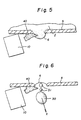
- FIG. 5 shows how a debris 40 can interfere with the meniscus 6 during the ink droplet formation.
- the droplet formation can be completely stopped by the ink surface condition change, due to the presence of the debris 40.
- outlet orifice plate 5 and elastomeric wiper blade 10 are shown for clarity.
- FIG. 6 shows another defect caused by the presence of a debris 40.
- the direction of the droplet 30 with satellites 31 shown as "X" is changed and will result in a degradation of the image.
- outlet orifice plate 5 and elastomeric wiper blade 10 are shown for clarity. Note that the outlet meniscus 6 has returned to the original state but debris 40 can also interfere with that process.
- FIG. 7 shows an ink jet printing apparatus 79 in accordance with the present invention, an ink jet head 75, a drive motor 70 linked with a gearbox 71, an ink jet head belt drive wheel 74, and the ink jet head drive belt 72 to drive the ink jet head 75 back and for across the print paper 85.
- the ink jet droplets are controlled by the position of the ink jet head 75. This position is monitored by a position encoder strip 76 and the image input from computer 100.
- the same computer controls the ink jet print head 75, drive motor 70, the cleaning roller. drive motor 83 which rotates at a desired velocity the cleaning roller 91.
- the guide 84 for back and forth translation of the ink jet head 75.
- the ink jet generates an image 81(shown in FIG.
- a mounting structure 87 supports all the associated mechanism for the ink jet printer 79.
- FIG. 8 shows the same printer as FIG. 7 but in a 90 degree rotated position. It can now be visualized how the ink jet head 75 with ink droplets 77 move across the paper 85 driven by the ink jet print head drive motor 70, a gearbox 71 to match motor speed with print speed.
- An ink jet head drive belt 72 driven by the belt drive wheel 74 drives the ink jet print head 75 across the total width of the print paper 85.
- the position of the print head 75 is metered by the position encoder strip 76.
- the encoder strip 76 At the right location determined by the computer 100 (shown in FIG. 7) and the encoder strip 76 a ink droplet 77 is deposited to form the image 81.
- the cleaning station 89 is mounted at the far right side end of the ink jet printer 79 and consists of a cleaning fluid tank 92, a cleaning roller 91, cleaning roller drive motor 83, and a cleaning roller drive belt 82.
- a number of different cleaning fluids can be used in accordance with the present invention.
- such fluids can include plain water, distilled water, alcohol or other water miscible solvents, and surfactants such as Zonyl, FSN (duPont).
- FIG. 9 shows the rotating cleaning roller 91 mounted to a shaft 93 is partially submerged in the cleaning fluid and spaced from the structure defining the orifices 9.
- the cleaning roller 91 as it rotates, carries by surface tension a coating 94 of cleaning liquid 95 to the outlet orifice plate 5.
- the roller or the roller surface is made from a material which can be surface coated by the cleaning fluid. Such roller surface material can be selected from the group consisting of aluminum, teflon, polyvinyl chlorine, stainless steel, glass, and titanium.
- the liquid will fill the cleaning cavity 80.
- FIG. 10 shows in an enlarged form how the fluid friction shown by vectors 101 causes the flow of the cleaning fluid to shear dirt and other particles 40 permanently from the outlet orifice plate 5.
- the vectors 101 indicate the flow of fluid in the cleaning cavity 80 caused by surface friction of orifice plate 5 and cleaning roller 91.
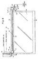
- FIG. 11 shows another embodiment of the invention cleaning an ink jet print head.
- the ink jet print head has moved (see arrows) from the print position (not shown) to a cleaning position.
- the head cleaning device 111 includes a cleaning liquid collection vessel 113, cleaning liquid supply 115 and exit 117 channels, and a rotating cleaning roller 119 mounted onto a shaft 121.
- a wall 147 separates the channels 115 and 117.
- Cleaning head 111 is brought into contact with outlet orifice plate 123 and a leak-proof seal is created by elastomer 125 at bottom of cleaning head 111.
- the outlet orifice plate 123 has a plurality of orifices of which only one orifice 151 is shown.
- Cleaning liquid 127 is pumped from cleaning liquid reservoir 133 into cleaning liquid supply channel 115 (by pump 131 with valves 137 and 139 in the open position and valve 141 in the closed position). Cap and vent 128 is provided on the reservoir 133.
- the head cleaning device 111 is substantially filled with cleaning liquid 127.
- Cleaning roller 119 (driven by computer 100 shown in FIG. 7) is rotated at the desired rotation rate. The rotation of the cleaning roller creates shear forces in the gap 118, thus producing a cleansing/scrubbing action capable of dislodging particles and/or debris accumulating around ink jet orifices.
- the size of gap 118 is controlled by the location of the cleaning roller, the diameter of the cleaning roller and the thickness of the elastomer seal 125.
- the dislodged debris is carried away by the cleaning liquid exiting in exit channel 117.
- particles and fibers may adhere to rotating cleaning roller 119, in which case the contaminated rotating cleaning roller 119 will most likely abrade outlet orifice plate 123.
- a scraper blade 149 attached to the roller end of wall 147 and in contact with cleaning roller 119 removes particles adhering to the roller and also prevents particles form entering the supply channel 115. It is preferred but not necessary that the scraper be flexible and in contact with cleaning roller 119.
- the exiting cleaning liquid preferably is re-circulated.
- a filter 129 interposed between the cleaning liquid reservoir 133 and pump 131 ensures that cleaning liquid entering the supply channel 115 is free of particles and fibers.
- a second filter 135 is also preferably used to filter cleaning liquid from exit channel 117 before entering reservoir 133.
- the cleaning liquid is fed into device 111 at a steady rate by pump 131.
- pump 131 is turned off and valve 139 is closed.
- Valve 137 (a 3-way valve) is positioned so that it is open to atmosphere only.
- Vacuum pump 143 is activated and valve 141 is opened to suck trapped cleaning liquid between valves 137 and 139 into collection receptacle 145. This operation prevents spillage of cleaning liquid when the device 111 is detached from outlet orifice plate 123. Further, the outlet orifice plate 123 is substantially dry, permitting the ink jet print head to function without impedance from liquid drops around the orifices.
- Cleaning liquid in collection receptacle 145 may be poured back into cleaning liquid reservoir 133 or can be pumped back into cleaning liquid reservoir 133 (pump and piping is not shown).
- the device 111 would function without wall 147 and scraper blade 149. In this case however, channels 115 and 117 would be combined to create one chamber with an inlet and an out let for the cleaning solution.
- This modification to head cleaning device 111 is not shown.
- the head cleaning device 111 will also function if the device is primed with cleaning liquid and connected to a cleaning liquid reservoir. When the cleaning roller rotates, cleaning liquid is siphoned from cleaning solution reservoir and pumped through device 111. The cleaning roller therefore has a dual function in that it cleans the outlet orifice plate 123 and also acts as a pump. This embodiment is not shown.
- the device 111 may also be configured to utilize a variety of cleaning liquids by incorporating appropriate valves and plumbing (not shown).
Description
- This invention relates to ink jet print head cleaning apparatus and more particularly relates to cleaning apparatus for cleaning multiple orifices belonging to such a print head.
- Many different types of digitally controlled printing systems of ink jet printing apparatus are presently being used. These ink jet printers use a variety of actuation mechanisms, a variety of marking materials, and a variety of recording media. For home applications, digital ink jet printing apparatus is the printing system of choice because low hardware cost make the printer affordable to every one. Another application for digital ink jet printing uses large format printers. It is a further requirement that these large format printers provide low cost copies with an ever improving quality. Ink jet printing technology is the first choice in today's art. Thus, there is a need for improved ways to make digitally controlled graphic arts media, such as billboards, large displays, and home photos for example, so that quality color images may be made at a high-speed and low cost, using standard or special paper.
- Ink jet printing has become recognized as a prominent contender in the digitally controlled, electronic printing arena because of its nonimpact, low-noise characteristics, its use of papers from plain paper to specialized high gloss papers and its avoidance of toner transfers and fixing. Ink jet printing mechanisms can be categorized as either continuous ink jet or droplet on demand ink jet. Continuous ink jet printing dates back to at least 1929. See U.S. Patent 1,941,001 to Hansell.
- U.S. Patent 3,373,437, issued to Sweet et al. in 1967, discloses an array of continuous ink jet orifices wherein ink droplets to be printed are selectively charged and deflected towards the recording medium. This technique is known as binary deflection continuous ink jet, and is used by several manufacturers, including Elmjet and Scitex.
- U.S. Patent 3,416,153, issued to Hertz et al. in 1966, discloses a method of achieving variable optical density of printed spots in continuous ink jet printing using the electrostatic dispersion of a charged droplet stream to modulate the number of droplets which pass through a small orifice. This technique is used in ink jet printers manufactured by Iris.
- U.S. Patent 3,878,519, h issued to Eaton in 1974, discloses a method and apparatus for synchronizing droplet formation in a liquid stream using electrostatic deflection by a charging tunnel and deflection plates.
- US Patent 4,346,387, issued to Hertz in 1982 discloses a method and apparatus for controlling the electric charge on droplets formed by the breaking up of a pressurized liquid stream at a droplet formation point located within the electric field having an electric potential gradient. Droplet formation is effected at a point in the field corresponding to the desired predetermined charge to be placed on the droplets at the point of their formation. In addition to charging tunnels, deflection plates are used to actually deflect droplets.
- Conventional continuous ink jet utilizes electrostatic charging tunnels that are placed close to the point where the droplets are formed in a stream. In this manner individual droplets may be charged. The charged droplets may be deflected downstream by the presence of deflector plates that have a large potential difference between them. A gutter (sometimes referred to as a "catcher") may be used to intercept the charged droplets, while the uncharged droplets are free to strike the recording medium. If there is no electric field present or if the break off point from the droplet is sufficiently far from the electric field (even if a portion of the stream before droplets break off is in the presence of an electric field), then charging will not occur.
- The on demand type ink jet printers are covered by hundreds of patents and describe two techniques for droplet formation. At every orifice, (about 30 to 200 are used for a consumer type printer) a pressurization actuator is used to produce the ink jet droplet. The two types of actuators are heat and piezo materials. The heater at a convenient location heats ink and a quantity will phase change into a gaseous steam bubble and raise the internal ink pressure sufficiently for an ink droplet to be expelled to a suitable receiver. The piezo ink actuator incorporates a piezo material. It is said to possess piezo electric properties if an electric charge is produced when a mechanical stress is applied. This is commonly referred to as the "generator effect" "The converse also holds true; an applied electric field will produce a mechanical stress in the material. This is commonly referred to as the "motor effect". Some naturally occurring materials possessing this characteristics are: quartz and tourmaline. Some artificially produced piezoelectric crystals are: Rochelle salt, ammonium dihydrogen phosphate (ADP) and lithium sulphate (LH). The class of materials used for piezo actuators in an ink jet print head possessing those properties includes polarized piezoelectric ceramics. They are typically referred to as ferroelectric materials. In contrast to the naturally occurring piezoelectric crystals, ferroelectric ceramics are of the "polycrystalline" structure. The most commonly produced piezoelectric ceramics are: lead zirconate titanate, barium titanate, lead titanate, and lead metaniobate. For the ink jet print head a ferroelectric ceramic is machined to produce ink chambers. The chamber is water proofed by gold plating and becomes a conductor to apply the charge and cause the piezo "motor effect". This "motor effect" causes the ink cavity to shrink, raise the internal pressure, and generate an ink droplet.
- Inks for high speed jet droplet printers must have a number of special characteristics. Typically, water-based inks have been used because of their conductivity and viscosity range. Thus, for use in a jet droplet printer the ink must be electrically conductive, having a resistivity below about 5000 ohm-cm and preferably below about 500 ohm-cm. For good flow through small orifices water-based inks generally have a viscosity in the range between about 1 to 15 centipoise at 25 degree C.
- Over and above this, the ink must be stable over a long period of time, compatible with the materials comprising the orifice plate and ink manifold, free of living organisms, and functional after printing. The required functional characteristics after printing are: smear resistance after printing, fast drying on paper, and waterproof when dry. Examples of different types of water-based jet droplet printing inks are found in U.S. Patents 3,903,034; 3,889,269; 3,870,528; 3,846,141; 3,776,642; and 3,705,043.
- The ink also has to incorporate a nondrying characteristic in the jet cavity so that the drying of ink in the cavity is hindered or slowed to such a degree that through occasional spitting of ink droplets the cavities can be kept open. The addition of glycol will facilitate the free flow of ink through the ink jet. Ink jet printing apparatus typically includes an ink jet print head that is exposed to the various environment where ink jet printing is utilized. The orifices are exposed to all kinds of air born particles. Particulate debris accumulates on the surfaces, forming around the orifices. The ink will combine with such particulate debris to form an interference burr to block the orifice or cause through an altered surface wetting to inhibit a proper formation of the ink droplet. That particulate debris has to be cleaned from the orifice to restore proper droplet formation. This cleaning commonly is achieved by wiping, spraying, vacuum suction, and/or spitting of ink through the orifice. The wiping as disclosed in GB-A-2 319 221 is the most common application.
- Inks used in ink jet printers can be said to have the following problems:
- 1) they require a large amount of energy to dry after printing;
- 2) large printed areas on paper usually cockle because of the amount of water present;
- 3) the printed images are sensitive to wet and dry rub;
- 4) the compositions of the ink usually require an anti-bacterial preservative to minimize the growth of bacteria in the ink;
- 5) the inks tend to dry out in and around the orifices resulting in clogging;
- 6) the wiping of the orifice plate causes wear on plate and wiper;
- 7) the wiper itself generates particles that clog the orifice;
- 8) cleaning cycles are time consuming and slow the productivity of ink jet printers. It is especially of concern in large format printers where frequent cleaning cycles interrupt the printing of an image; and
- 9) when a special printing pattern is initiated to compensate for plugged or badly performing orifices, the printing rate declines.
-
- Some of these problems may be overcome by the use of polar, conductive organic solvent based ink formulations. However, the use of non-polar organic solvents is generally precluded by their lack of electrical conductivity. The addition of solvent soluble salts can make such inks conductive, but such salts are often toxic, corrosive, and unstable.
- It is an object of the invention to provide a cleaning apparatus for cleaning multiple orifices belonging to an inkjet print head.
- For use in an ink jet printer having an ink jet print head defining a plurality of orifices for ejecting ink droplets, a cleaning apparatus as defined in claims 1 & 7 for cleaning multiple orifices belonging to the print head, comprising:
- a) a body defining an ink cleaning cavity spaced from a printing position for receiving cleaning fluid;
- b) a roller disposed in the cleaning cavity and partially submerged in the cleaning fluid and spaced from the print head;
- c) means for rotating the roller so that the fluid coats the roller and is carried by surface tension around the roller; and
- d) means for bringing the structure into proximity with the cleaning roller so that the orifices are cleaned by the cleaning fluid carried on the roller and delivered through the cleaning cavity to the print head.
-
- An advantage of the present invention is that rapid cleaning of orifices is accomplished in such a short time.
- Another advantage of the present invention is that cleaning fluid on the roller is replenished at a predetermined rate and removes waste ink and particulate debris permanently from the ink jet print head.
- Yet another advantage of this invention is that the cleaning fluid on the roller can have a substantial thickness thereby minimizing the requirements for mechanical tolerances.
- Still another advantage of this cleaning technique is that with no mechanical rubbing, the wear of the delicate orifice plate is eliminated or greatly reduced. The replacement of the ink jet head will be less frequent and more of the orifices will stay functional to result in a higher image quality.
- Another advantage is that individual inks can be cleaned by selecting the rotation rate of the roller to change the turbulence or agitation rate. In this way, the speed of the roller can be selected to match the cleaning needs of a particular ink. In other words, red , green, and blue inks in the same cartridge can have different roller speeds.
-
- FIG. 1 is a prior art cross sectional schematic view of a typical piezo electric ink jet print head;
- FIG. 2 is a schematic showing an ink droplet exit orifice in the FIG. 1 structure and an elastomeric wiper blade commonly used for cleaning the orifice plate;
- FIG. 3 the ink droplet as it begins to form in the orifice of FIG. 1;
- FIG. 4 shows the ink droplet after formation with the orifice of FIG.. 1;
- FIG. 5 shows the interference of the particulate debris with the formation of an ink droplet;
- FIG. 6 shows that a particulate material can cause a change of direction of ink droplets;
- FIG. 7 shows a schematic of ink jet printing apparatus in accordance with the present invention which shows a print head and a cleaning station;
- FIG. 8 shows the same as FIG. 7 but a different perspective for clarification of illustration;
- FIG. 9 shows the cleaning mechanism in accordance with the present invention;
- FIG. 10 shows an enlargement of the cleaning fluid coating depicting its turbulent counter clockwise flow; and
- FIG. 11 shows a schematic view of another embodiment of the present invention which depicts an ink jet print head and a head cleaning device.
-
- FIG.. 1 shows a prior art cross sectional view of an ink jet print head 1. Orifices defining structures such as the depicted
outlet plate 5 includesorifice 9 having a diameter "d" and can be manufactured by electro-forming or sheet metal fabrication methods. It will be understood that theoutlet plate 5 actually includes a plurality of orifices for forming multiple ink droplets. Theoutlet plate 5 is glued to thepiezo walls 3.Ink 2 is included in apumping cavity 8. An inlet orifice 7 formed in a inlet plate 4 permits ink to be delivered to thepumping cavity 8. Ameniscus 6 of ink is formed in theorifice 9. - FIG. 2 shows the
outlet plate 5 with theink outlet meniscus 6 and aelastomeric wiper blade 10 in contact with the outlet orifice plate. The blade is in position to wipe across the diameter "d" of theorifice 9 to clean any ink or other particulate debris that could interfere with the proper functioning of the ink jet print head 1. - FIG. 3 shows the
meniscus 6 as it changes from an inward curve to an outward curve during the early stages before an actual ink droplet is manufactured. For reference and clarity theelastomeric wiper blade 10 and theoutlet orifice plate 5 are also shown. - FIG. 4 shows the completed
ink droplet 30, and its direction which is indicated by the arrow "X". Also shown are (as often is the case when an ink droplet is formed) twoink droplet satellites 31. The formation ofsatellites 31 is chaotic and can incorporate any number ofink droplet satellites 31 from 0 up to 10. These numbers ofsatellites 31 have been observed. Note that theoutlet meniscus 6 has returned to the original state. - FIG. 5 shows how a
debris 40 can interfere with themeniscus 6 during the ink droplet formation. As theink 2 touches thedebris 40, the droplet formation can be completely stopped by the ink surface condition change, due to the presence of thedebris 40. Againoutlet orifice plate 5 andelastomeric wiper blade 10 are shown for clarity. - FIG. 6 shows another defect caused by the presence of a
debris 40. The direction of thedroplet 30 withsatellites 31 shown as "X" is changed and will result in a degradation of the image. Againoutlet orifice plate 5 andelastomeric wiper blade 10 are shown for clarity. Note that theoutlet meniscus 6 has returned to the original state butdebris 40 can also interfere with that process. - FIG. 7 shows an ink
jet printing apparatus 79 in accordance with the present invention, anink jet head 75, adrive motor 70 linked with agearbox 71, an ink jet headbelt drive wheel 74, and the ink jethead drive belt 72 to drive theink jet head 75 back and for across theprint paper 85. The ink jet droplets are controlled by the position of theink jet head 75. This position is monitored by aposition encoder strip 76 and the image input fromcomputer 100. The same computer controls the inkjet print head 75, drivemotor 70, the cleaning roller. drivemotor 83 which rotates at a desired velocity the cleaningroller 91. Also shown are theguide 84 for back and forth translation of theink jet head 75. The ink jet generates an image 81(shown in FIG. 8) on theprint paper 85. Theprint paper 85 is supported by theplaten roller 78 and registration of the paper is controlled by thecapstan roller 88. Both rollers,platen 78 andcapstan 88 are driven by a motor not shown and are controlled by thecomputer 100. Also shown is a cleaningroller 91 with the cleaningroller drive belt 82 connecting thecleaning drive motor 83 to the cleaningroller 91. A mountingstructure 87 supports all the associated mechanism for theink jet printer 79. - FIG. 8 shows the same printer as FIG. 7 but in a 90 degree rotated position. It can now be visualized how the
ink jet head 75 withink droplets 77 move across thepaper 85 driven by the ink jet printhead drive motor 70, agearbox 71 to match motor speed with print speed. An ink jethead drive belt 72 driven by thebelt drive wheel 74 drives the inkjet print head 75 across the total width of theprint paper 85. The position of theprint head 75 is metered by theposition encoder strip 76. At the right location determined by the computer 100 (shown in FIG. 7) and the encoder strip 76 aink droplet 77 is deposited to form theimage 81. When the inkjet print head 75 reaches the far end of theprint paper 85 it de-accelerates in the indicated direction and distance of arrow "d". When reversing' indicated by the direction and distance of arrow "a", theprint head 75 re-accelerates to the correct print speed. This turn around deceleration ("d") and re-acceleration ("a") time is used to accomplish the cleaning without added time for the inkjet print head 75. The cleaning station 89 is mounted at the far right side end of theink jet printer 79 and consists of a cleaning fluid tank 92, a cleaningroller 91, cleaningroller drive motor 83, and a cleaningroller drive belt 82. A number of different cleaning fluids can be used in accordance with the present invention. For example, such fluids can include plain water, distilled water, alcohol or other water miscible solvents, and surfactants such as Zonyl, FSN (duPont). - FIG. 9 shows the
rotating cleaning roller 91 mounted to ashaft 93 is partially submerged in the cleaning fluid and spaced from the structure defining theorifices 9. The cleaningroller 91, as it rotates, carries by surface tension acoating 94 of cleaningliquid 95 to theoutlet orifice plate 5. The roller or the roller surface is made from a material which can be surface coated by the cleaning fluid. Such roller surface material can be selected from the group consisting of aluminum, teflon, polyvinyl chlorine, stainless steel, glass, and titanium. The liquid will fill thecleaning cavity 80. The liquid surface friction between the stationaryoutlet orifice plate 5 and therotating cleaning roller 91 will cause a great amount of turbulence and liquid shearing to remove dirt and ink from theoutlet orifice plate 5 in and near theorifices 6. An arrow marked "r" indicates one of the possible two the rotational direction of the cleaningroller 91. - FIG. 10 shows in an enlarged form how the fluid friction shown by
vectors 101 causes the flow of the cleaning fluid to shear dirt andother particles 40 permanently from theoutlet orifice plate 5. Thevectors 101 indicate the flow of fluid in thecleaning cavity 80 caused by surface friction oforifice plate 5 and cleaningroller 91. - FIG. 11 shows another embodiment of the invention cleaning an ink jet print head. The ink jet print head has moved (see arrows) from the print position (not shown) to a cleaning position. The head cleaning device 111 includes a cleaning
liquid collection vessel 113, cleaningliquid supply 115 andexit 117 channels, and arotating cleaning roller 119 mounted onto ashaft 121. Awall 147 separates thechannels outlet orifice plate 123 and a leak-proof seal is created byelastomer 125 at bottom of cleaning head 111. Theoutlet orifice plate 123 has a plurality of orifices of which only oneorifice 151 is shown.Cleaning liquid 127 is pumped from cleaningliquid reservoir 133 into cleaning liquid supply channel 115 (bypump 131 withvalves valve 141 in the closed position). Cap and vent 128 is provided on thereservoir 133. The head cleaning device 111 is substantially filled with cleaningliquid 127. Cleaning roller 119 (driven bycomputer 100 shown in FIG. 7) is rotated at the desired rotation rate. The rotation of the cleaning roller creates shear forces in thegap 118, thus producing a cleansing/scrubbing action capable of dislodging particles and/or debris accumulating around ink jet orifices. The size ofgap 118 is controlled by the location of the cleaning roller, the diameter of the cleaning roller and the thickness of theelastomer seal 125. The dislodged debris is carried away by the cleaning liquid exiting inexit channel 117. However, particles and fibers may adhere torotating cleaning roller 119, in which case the contaminatedrotating cleaning roller 119 will most likely abradeoutlet orifice plate 123. In order to minimize this, ascraper blade 149 attached to the roller end ofwall 147 and in contact with cleaningroller 119 removes particles adhering to the roller and also prevents particles form entering thesupply channel 115. It is preferred but not necessary that the scraper be flexible and in contact with cleaningroller 119. The exiting cleaning liquid preferably is re-circulated. Afilter 129 interposed between the cleaningliquid reservoir 133 and pump 131 ensures that cleaning liquid entering thesupply channel 115 is free of particles and fibers. Asecond filter 135 is also preferably used to filter cleaning liquid fromexit channel 117 before enteringreservoir 133. The cleaning liquid is fed into device 111 at a steady rate bypump 131. At a desired time, pump 131 is turned off andvalve 139 is closed. Valve 137 (a 3-way valve) is positioned so that it is open to atmosphere only.Vacuum pump 143 is activated andvalve 141 is opened to suck trapped cleaning liquid betweenvalves collection receptacle 145. This operation prevents spillage of cleaning liquid when the device 111 is detached fromoutlet orifice plate 123. Further, theoutlet orifice plate 123 is substantially dry, permitting the ink jet print head to function without impedance from liquid drops around the orifices. Cleaning liquid incollection receptacle 145 may be poured back into cleaningliquid reservoir 133 or can be pumped back into cleaning liquid reservoir 133 (pump and piping is not shown). - It is understood that the device 111 would function without
wall 147 andscraper blade 149. In this case however,channels outlet orifice plate 123 and also acts as a pump. This embodiment is not shown. The device 111 may also be configured to utilize a variety of cleaning liquids by incorporating appropriate valves and plumbing (not shown).
Claims (10)
- An ink jet printer having an ink jet head (1) defining a plurality of orifices (9) for ejecting ink droplets (77), a body (111) defining an ink cleaning cavity (80) spaced from a printing position for receiving cleaning fluid and a roller (119) disposed in the cleaning cavity and partially submerged in the cleaning fluid, said ink jet printer is characterized by:a) rotation means (100) for rotating the roller so that the fluid coats the roller and is carried by surface tension around the roller; andb) positioning means for bringing the orifices and the roller into a proximate and separate relation wherein the orifices enter the flow of cleaning fluid so that the orifices are cleaned by the cleaning fluid carried on the roller.
- The ink jet printer of claim 1 wherein the rotating roller is capable of creating a high turbulence (101) of the cleaning fluid between the roller and the orifices.
- The ink jet printer of claim 2 wherein the roller has a surface thereon made from a material which can be surface coated by the cleaning fluid.
- The ink jet printer of claim 3 wherein the roller surface material is selected from the group consisting of aluminum, teflon, polyvinyl chlorine, stainless steel, glass, and titanium.
- The ink jet printer of claim 1 further comprising a scrapper blade (149) in contact with the roller to remove cleaning liquid and debris from the roller.
- The ink jet printer of claim 1 wherein the roller includes a material capable of carrying cleaning liquid.
- An ink jet printer having a print head defining a plurality of orifices for ejecting ink droplets, a source of cleaning fluid, a cleaning member having a surface partially dipped in the cleaning fluid, said printer is characterized by:a) a first drive mechanism to move the cleaning member surface creating a flow of cleaning fluid on the surface; andb) a second drive mechanism to advance the print head and the cleaning member surface into a proximate and separate relations wherein at least one of the orifices of the print head enters the flow of cleaning fluid.
- The ink jet printer of claim 7 wherein the proximate and separate relation is defined so that at least one of the orifices are entered into the flow of fluid to disrupt the flow of cleaning fluid in a manner that creates a turbulent flow about the at least one orifice.
- The ink jet printer of claim 7 wherein said second drive mechanism advances the print head relative to the surface so that selected ones of the orifices of the print head are entered into the flow of cleaning fluid.
- The ink jet printer of claim 1 further comprising an exit channel wherein the moving cleaning member surface causes cleaning fluid to flow into the exit channel.
Applications Claiming Priority (2)
| Application Number | Priority Date | Filing Date | Title |
|---|---|---|---|
| US09/159,447 US6281909B1 (en) | 1998-09-24 | 1998-09-24 | Cleaning orifices in ink jet printing apparatus |
| US159447 | 1998-09-24 |
Publications (2)
| Publication Number | Publication Date |
|---|---|
| EP0988978A1 EP0988978A1 (en) | 2000-03-29 |
| EP0988978B1 true EP0988978B1 (en) | 2003-01-15 |
Family
ID=22572648
Family Applications (1)
| Application Number | Title | Priority Date | Filing Date |
|---|---|---|---|
| EP99202984A Expired - Lifetime EP0988978B1 (en) | 1998-09-24 | 1999-09-13 | Cleaning of orifices in an ink jet printing apparatus |
Country Status (4)
| Country | Link |
|---|---|
| US (2) | US6281909B1 (en) |
| EP (1) | EP0988978B1 (en) |
| JP (1) | JP2000094703A (en) |
| DE (1) | DE69904898T2 (en) |
Families Citing this family (37)
| Publication number | Priority date | Publication date | Assignee | Title |
|---|---|---|---|---|
| US7160389B2 (en) * | 1998-01-09 | 2007-01-09 | Fastar, Ltd. | System and method for cleaning and priming an extrusion head |
| US6281909B1 (en) | 1998-09-24 | 2001-08-28 | Eastman Kodak Company | Cleaning orifices in ink jet printing apparatus |
| US6367905B1 (en) * | 2000-06-09 | 2002-04-09 | Eastman Kodak Company | Print head cleaning assembly with roller and method for an ink jet print head with fixed gutter |
| US6554391B1 (en) * | 2000-07-20 | 2003-04-29 | Eastman Kodak Company | Rotating disk cleaning assembly apparatus and method for an ink jet print head with fixed gutter |
| US6905552B2 (en) * | 2001-12-26 | 2005-06-14 | Xerox Corporation | Contactless cleaning of vertical ink jet printheads |
| US6660103B1 (en) | 2002-03-28 | 2003-12-09 | Vutek, Inc. | Cleaning process for ink jet printheads |
| US7153689B2 (en) | 2002-08-01 | 2006-12-26 | Agilent Technologies, Inc. | Apparatus and methods for cleaning and priming droplet dispensing devices |
| CN1331677C (en) * | 2003-04-11 | 2007-08-15 | 珠海天威飞马打印耗材有限公司 | Ink box cleaning machine |
| US7357498B2 (en) * | 2003-12-24 | 2008-04-15 | Seiko Epson Corporation | Method of filling liquid into liquid containing member, liquid filling apparatus and method of inspecting liquid containing member |
| JP4141946B2 (en) * | 2003-12-24 | 2008-08-27 | セイコーエプソン株式会社 | Inspection method for liquid bag |
| AT500098B8 (en) * | 2003-12-30 | 2007-02-15 | Durst Phototech Digital Tech | DEVICE FOR CLEANING A PRINT HEAD |
| US7360853B2 (en) * | 2004-03-04 | 2008-04-22 | Fujifilm Dimatix, Inc. | Morphology-corrected printing |
| JP2005313606A (en) * | 2004-03-30 | 2005-11-10 | Seiko Epson Corp | Wiper cleaning device for liquid ejection device |
| KR20060106288A (en) * | 2005-04-07 | 2006-10-12 | 삼성전자주식회사 | Roll brushing apparatus, ink jet head cleaning system and method including the same |
| JP2006305772A (en) * | 2005-04-26 | 2006-11-09 | Sharp Corp | Inkjet recorder, wiping method, and wiping blade |
| JP2007090853A (en) * | 2005-09-02 | 2007-04-12 | Sony Corp | Liquid discharge device |
| US7367648B2 (en) * | 2005-10-11 | 2008-05-06 | Silverbrook Research Pty Ltd | Printhead maintenance assembly with film transport of ink |
| US7758174B2 (en) * | 2005-10-11 | 2010-07-20 | Silverbrook Research Pty Ltd | Ink supply system comprising air compressor and in-line valve |
| US7506952B2 (en) * | 2005-10-11 | 2009-03-24 | Silverbrook Research Pty Ltd | Method of removing particulates from a printhead using film transfer |
| US7695093B2 (en) * | 2005-10-11 | 2010-04-13 | Silverbrook Research Pty Ltd | Method of removing flooded ink from a printhead using a disposable sheet |
| US7401886B2 (en) * | 2005-10-11 | 2008-07-22 | Silverbrook Research Pty Ltd | Method of removing ink from a printhead using film transfer |
| US7370936B2 (en) * | 2005-10-11 | 2008-05-13 | Silverbrook Research Pty Ltd | Method of maintaining a printhead using film transport of ink |
| JP4857764B2 (en) * | 2005-12-27 | 2012-01-18 | ブラザー工業株式会社 | Head cleaning device |
| US20070206038A1 (en) * | 2006-03-03 | 2007-09-06 | Richard Baker | Ink jet printing with multiple conveyors |
| US7524050B2 (en) * | 2006-04-11 | 2009-04-28 | Fujifilm Dimatix, Inc. | Ink jet printing |
| US20070279467A1 (en) * | 2006-06-02 | 2007-12-06 | Michael Thomas Regan | Ink jet printing system for high speed/high quality printing |
| KR101254275B1 (en) * | 2006-06-20 | 2013-04-23 | 가부시키가이샤 아루박 | Apparatus and method for coating polyimide layer on the glass |
| US7641304B2 (en) * | 2006-07-31 | 2010-01-05 | Silverbrook Research Pty Ltd | Printhead maintenance system comprising foaming system and foam transport assembly |
| US7753470B2 (en) * | 2006-07-31 | 2010-07-13 | Silverbrook Research Pty Ltd | Printhead assembly with ink supply system and foaming system |
| TW200821031A (en) * | 2006-11-10 | 2008-05-16 | Hi Touch Imaging Tech Co Ltd | Filter cleaning apparatus capable of cleaning a filter without dismantling the filter |
| KR20080112542A (en) * | 2007-06-21 | 2008-12-26 | 삼성전자주식회사 | Ink-jet image forming apparatus |
| JP5280886B2 (en) * | 2009-02-25 | 2013-09-04 | 富士フイルム株式会社 | Head cleaning apparatus, image recording apparatus, and head cleaning method |
| JP5280887B2 (en) * | 2009-02-25 | 2013-09-04 | 富士フイルム株式会社 | Head cleaning apparatus, image recording apparatus, and head cleaning method |
| JP5143779B2 (en) * | 2009-03-31 | 2013-02-13 | 富士フイルム株式会社 | Head cleaning apparatus, image recording apparatus, and head cleaning method |
| SG176652A1 (en) * | 2009-06-03 | 2012-01-30 | Novartis Ag | Maintenance unit for print head |
| FR3093944B1 (en) * | 2019-03-22 | 2021-03-19 | Poietis | CARTRIDGE FOR BIOIMPRESSION |
| CN110884267B (en) * | 2019-11-14 | 2021-07-06 | Tcl华星光电技术有限公司 | Cleaning device |
Family Cites Families (22)
| Publication number | Priority date | Publication date | Assignee | Title |
|---|---|---|---|---|
| US3373437A (en) | 1964-03-25 | 1968-03-12 | Richard G. Sweet | Fluid droplet recorder with a plurality of jets |
| GB1143079A (en) | 1965-10-08 | 1969-02-19 | Hertz Carl H | Improvements in or relating to recording devices for converting electrical signals |
| US3903034A (en) | 1970-12-07 | 1975-09-02 | Dick Co Ab | Offset jet printing ink |
| US3705043A (en) | 1970-12-07 | 1972-12-05 | Dick Co Ab | Infrared absorptive jet printing ink composition |
| US3846141A (en) | 1970-12-07 | 1974-11-05 | Dick Co Ab | Jet printing ink composition |
| US3776642A (en) | 1972-08-01 | 1973-12-04 | Dickey John Corp | Grain analysis computer |
| DE2258835A1 (en) | 1972-12-01 | 1974-06-12 | Agfa Gevaert Ag | Aqueous INK FOR THE INK JET PROCESS |
| US3870528A (en) | 1973-12-17 | 1975-03-11 | Ibm | Infrared and visible dual dye jet printer ink |
| US3878519A (en) | 1974-01-31 | 1975-04-15 | Ibm | Method and apparatus for synchronizing droplet formation in a liquid stream |
| CA1158706A (en) | 1979-12-07 | 1983-12-13 | Carl H. Hertz | Method and apparatus for controlling the electric charge on droplets and ink jet recorder incorporating the same |
| GB2203994B (en) | 1987-03-31 | 1991-12-11 | Canon Kk | Liquid injection recording apparatus and liquid-repellent process method used for the apparatus |
| US4849769A (en) * | 1987-06-02 | 1989-07-18 | Burlington Industries, Inc. | System for ultrasonic cleaning of ink jet orifices |
| US5305015A (en) | 1990-08-16 | 1994-04-19 | Hewlett-Packard Company | Laser ablated nozzle member for inkjet printhead |
| JP3175366B2 (en) | 1992-12-01 | 2001-06-11 | 富士ゼロックス株式会社 | Inkjet recording ink |
| US5350616A (en) | 1993-06-16 | 1994-09-27 | Hewlett-Packard Company | Composite orifice plate for ink jet printer and method for the manufacture thereof |
| US5426458A (en) | 1993-08-09 | 1995-06-20 | Hewlett-Packard Corporation | Poly-p-xylylene films as an orifice plate coating |
| US5738716A (en) | 1996-08-20 | 1998-04-14 | Eastman Kodak Company | Color pigmented ink jet ink set |
| US5914734A (en) * | 1996-11-13 | 1999-06-22 | Hewlett-Packard Company | Printhead servicing system and method using a moveable wiper between a fluid source and a printhead |
| US5725647A (en) | 1996-11-27 | 1998-03-10 | Minnesota Mining And Manufacturing Company | Pigmented inks and humectants used therewith |
| US5997127A (en) * | 1998-09-24 | 1999-12-07 | Eastman Kodak Company | Adjustable vane used in cleaning orifices in inkjet printing apparatus |
| US6281909B1 (en) | 1998-09-24 | 2001-08-28 | Eastman Kodak Company | Cleaning orifices in ink jet printing apparatus |
| US6047715A (en) * | 1998-12-18 | 2000-04-11 | Eastman Kodak Company | Turbulent cleaning action for ink jet print heads and orifices |
-
1998
- 1998-09-24 US US09/159,447 patent/US6281909B1/en not_active Expired - Lifetime
-
1999
- 1999-09-13 DE DE69904898T patent/DE69904898T2/en not_active Expired - Fee Related
- 1999-09-13 EP EP99202984A patent/EP0988978B1/en not_active Expired - Lifetime
- 1999-09-24 JP JP11270250A patent/JP2000094703A/en active Pending
-
2001
- 2001-08-27 US US09/939,868 patent/US6592201B2/en not_active Expired - Fee Related
Also Published As
| Publication number | Publication date |
|---|---|
| DE69904898D1 (en) | 2003-02-20 |
| US6592201B2 (en) | 2003-07-15 |
| EP0988978A1 (en) | 2000-03-29 |
| US20020140762A1 (en) | 2002-10-03 |
| US6281909B1 (en) | 2001-08-28 |
| DE69904898T2 (en) | 2003-11-06 |
| JP2000094703A (en) | 2000-04-04 |
Similar Documents
| Publication | Publication Date | Title |
|---|---|---|
| EP0988978B1 (en) | Cleaning of orifices in an ink jet printing apparatus | |
| EP1060894B1 (en) | Multi-fluidic cleaning for ink jet print heads | |
| EP1005997B1 (en) | A self-cleaning ink jet printer with reverse flow and method of assembling the printer | |
| US5997127A (en) | Adjustable vane used in cleaning orifices in inkjet printing apparatus | |
| EP1088665B1 (en) | A self-cleaning ink jet printer system with a reversible fluid flow and a rotating roller and method of assembling the printer system | |
| EP1088664B1 (en) | A self-cleaning ink jet printer system with a reversible fluid flow and a method of assembling the printer system | |
| US6350007B1 (en) | Self-cleaning ink jet printer using ultrasonics and method of assembling same | |
| EP0992355A2 (en) | Cleaning and repairing fluid for printhead cleaning | |
| US10730305B2 (en) | Inkjet printing system with non-contact cleaning station | |
| US6183057B1 (en) | Self-cleaning ink jet printer having ultrasonics with reverse flow and method of assembling same | |
| JP2000198214A (en) | Ink jet printer with cleaning mechanism and its assembly method | |
| US6145952A (en) | Self-cleaning ink jet printer and method of assembling same | |
| EP1016531B1 (en) | A self-cleaning ink jet printer with oscillating septum and method of operating the printer | |
| EP1016530B1 (en) | A self-cleaning ink jet printer with oscillating septum and method of assembling the printer | |
| US6406122B1 (en) | Method and cleaning assembly for cleaning an ink jet print head in a self-cleaning ink jet printer system | |
| CA2399162A1 (en) | Cleaning ink jet printheads and orifices | |
| EP1162070B1 (en) | Print head cleaning assembly with roller and method for an ink jet print head with fixed gutter | |
| US6047715A (en) | Turbulent cleaning action for ink jet print heads and orifices | |
| US6905552B2 (en) | Contactless cleaning of vertical ink jet printheads | |
| JP2002036575A (en) | Rotary disk cleaning assembly apparatus and method for ink jet printing head equipped with fixed groove | |
| CN109397881A (en) | For restoring the method and system of faulty spray head | |
| EP0992354A2 (en) | Cleaning fluid for inkjet printers |
Legal Events
| Date | Code | Title | Description |
|---|---|---|---|
| PUAI | Public reference made under article 153(3) epc to a published international application that has entered the european phase |
Free format text: ORIGINAL CODE: 0009012 |
|
| AK | Designated contracting states |
Kind code of ref document: A1 Designated state(s): DE FR GB |
|
| AX | Request for extension of the european patent |
Free format text: AL;LT;LV;MK;RO;SI |
|
| 17P | Request for examination filed |
Effective date: 20000908 |
|
| AKX | Designation fees paid |
Free format text: DE FR GB |
|
| 17Q | First examination report despatched |
Effective date: 20010731 |
|
| GRAH | Despatch of communication of intention to grant a patent |
Free format text: ORIGINAL CODE: EPIDOS IGRA |
|
| GRAH | Despatch of communication of intention to grant a patent |
Free format text: ORIGINAL CODE: EPIDOS IGRA |
|
| GRAA | (expected) grant |
Free format text: ORIGINAL CODE: 0009210 |
|
| AK | Designated contracting states |
Kind code of ref document: B1 Designated state(s): DE FR GB |
|
| REG | Reference to a national code |
Ref country code: GB Ref legal event code: FG4D |
|
| REF | Corresponds to: |
Ref document number: 69904898 Country of ref document: DE Date of ref document: 20030220 Kind code of ref document: P |
|
| ET | Fr: translation filed | ||
| PLBE | No opposition filed within time limit |
Free format text: ORIGINAL CODE: 0009261 |
|
| STAA | Information on the status of an ep patent application or granted ep patent |
Free format text: STATUS: NO OPPOSITION FILED WITHIN TIME LIMIT |
|
| 26N | No opposition filed |
Effective date: 20031016 |
|
| PGFP | Annual fee paid to national office [announced via postgrant information from national office to epo] |
Ref country code: GB Payment date: 20060804 Year of fee payment: 8 |
|
| PGFP | Annual fee paid to national office [announced via postgrant information from national office to epo] |
Ref country code: FR Payment date: 20060906 Year of fee payment: 8 |
|
| PGFP | Annual fee paid to national office [announced via postgrant information from national office to epo] |
Ref country code: DE Payment date: 20060929 Year of fee payment: 8 |
|
| GBPC | Gb: european patent ceased through non-payment of renewal fee |
Effective date: 20070913 |
|
| PG25 | Lapsed in a contracting state [announced via postgrant information from national office to epo] |
Ref country code: DE Free format text: LAPSE BECAUSE OF NON-PAYMENT OF DUE FEES Effective date: 20080401 |
|
| REG | Reference to a national code |
Ref country code: FR Ref legal event code: ST Effective date: 20080531 |
|
| PG25 | Lapsed in a contracting state [announced via postgrant information from national office to epo] |
Ref country code: FR Free format text: LAPSE BECAUSE OF NON-PAYMENT OF DUE FEES Effective date: 20071001 |
|
| PG25 | Lapsed in a contracting state [announced via postgrant information from national office to epo] |
Ref country code: GB Free format text: LAPSE BECAUSE OF NON-PAYMENT OF DUE FEES Effective date: 20070913 |