EP1016531B1 - A self-cleaning ink jet printer with oscillating septum and method of operating the printer - Google Patents
A self-cleaning ink jet printer with oscillating septum and method of operating the printer Download PDFInfo
- Publication number
- EP1016531B1 EP1016531B1 EP99204276A EP99204276A EP1016531B1 EP 1016531 B1 EP1016531 B1 EP 1016531B1 EP 99204276 A EP99204276 A EP 99204276A EP 99204276 A EP99204276 A EP 99204276A EP 1016531 B1 EP1016531 B1 EP 1016531B1
- Authority
- EP
- European Patent Office
- Prior art keywords
- septum
- liquid
- gap
- cleaning
- cavity
- Prior art date
- Legal status (The legal status is an assumption and is not a legal conclusion. Google has not performed a legal analysis and makes no representation as to the accuracy of the status listed.)
- Expired - Lifetime
Links
Images


Classifications
-
- B—PERFORMING OPERATIONS; TRANSPORTING
- B41—PRINTING; LINING MACHINES; TYPEWRITERS; STAMPS
- B41J—TYPEWRITERS; SELECTIVE PRINTING MECHANISMS, i.e. MECHANISMS PRINTING OTHERWISE THAN FROM A FORME; CORRECTION OF TYPOGRAPHICAL ERRORS
- B41J2/00—Typewriters or selective printing mechanisms characterised by the printing or marking process for which they are designed
- B41J2/005—Typewriters or selective printing mechanisms characterised by the printing or marking process for which they are designed characterised by bringing liquid or particles selectively into contact with a printing material
- B41J2/01—Ink jet
- B41J2/135—Nozzles
- B41J2/165—Preventing or detecting of nozzle clogging, e.g. cleaning, capping or moistening for nozzles
- B41J2/16517—Cleaning of print head nozzles
- B41J2/16552—Cleaning of print head nozzles using cleaning fluids
-
- B—PERFORMING OPERATIONS; TRANSPORTING
- B41—PRINTING; LINING MACHINES; TYPEWRITERS; STAMPS
- B41J—TYPEWRITERS; SELECTIVE PRINTING MECHANISMS, i.e. MECHANISMS PRINTING OTHERWISE THAN FROM A FORME; CORRECTION OF TYPOGRAPHICAL ERRORS
- B41J2/00—Typewriters or selective printing mechanisms characterised by the printing or marking process for which they are designed
- B41J2/005—Typewriters or selective printing mechanisms characterised by the printing or marking process for which they are designed characterised by bringing liquid or particles selectively into contact with a printing material
- B41J2/01—Ink jet
- B41J2/135—Nozzles
- B41J2/165—Preventing or detecting of nozzle clogging, e.g. cleaning, capping or moistening for nozzles
- B41J2/16585—Preventing or detecting of nozzle clogging, e.g. cleaning, capping or moistening for nozzles for paper-width or non-reciprocating print heads
-
- B—PERFORMING OPERATIONS; TRANSPORTING
- B41—PRINTING; LINING MACHINES; TYPEWRITERS; STAMPS
- B41J—TYPEWRITERS; SELECTIVE PRINTING MECHANISMS, i.e. MECHANISMS PRINTING OTHERWISE THAN FROM A FORME; CORRECTION OF TYPOGRAPHICAL ERRORS
- B41J2/00—Typewriters or selective printing mechanisms characterised by the printing or marking process for which they are designed
- B41J2/005—Typewriters or selective printing mechanisms characterised by the printing or marking process for which they are designed characterised by bringing liquid or particles selectively into contact with a printing material
- B41J2/01—Ink jet
- B41J2/17—Ink jet characterised by ink handling
- B41J2/18—Ink recirculation systems
- B41J2/185—Ink-collectors; Ink-catchers
Definitions
- This invention generally relates to ink jet printer apparatus and methods and more particularly relates to a self-cleaning ink jet printer with oscillating septum and ultrasonics and method of operating the printer.
- An ink jet printer produces images on a receiver by ejecting ink droplets onto the receiver in an imagewise fashion.
- the advantages of non-impact, low-noise, low energy use, and low cost operation in addition to the capability of the printer to print on plain paper are largely responsible for the wide acceptance of ink jet printers in the marketplace.
- continuous ink jet printers utilize electrostatic charging tunnels that are placed close to the point where ink droplets are being ejected in the form of a stream. Selected ones of the droplets are electrically charged by the charging tunnels. The charged droplets are deflected downstream by the presence of deflector plates that have a predetermined electric potential difference between them. A gutter may be used to intercept the charged droplets, while the uncharged droplets are free to strike the recording medium.
- a pressurization actuator is used to produce the ink jet droplet.
- either one of two types of actuators may be used.
- These two types of actuators are heat actuators and piezoelectric actuators.
- heat actuators a heater placed at a convenient location heats the ink and a quantity of the ink will phase change into a gaseous steam bubble and raise the internal ink pressure sufficiently for an ink droplet to be expelled to the recording medium.
- piezoelectric actuators A piezoelectric material is used, which piezoelectric material possess piezoelectric properties such that an electric field is produced when a mechanical stress is applied.
- Inks for high speed ink jet printers whether of the "continuous" or “piezoelectric” type, must have a number of special characteristics.
- the ink should incorporate a nondrying characteristic, so that drying of ink in the ink ejection chamber is hindered or slowed to such a state that by occasional spitting of ink droplets, the cavities and corresponding orifices are kept open.
- glycol facilitates free flow of ink through the ink jet chamber.
- the ink jet print head is exposed to the environment where the ink jet printing occurs.
- the previously mentioned orifices are exposed to many kinds of air born particulates.
- Particulate debris may accumulate on surfaces formed around the orifices and may accumulate in the orifices and chambers themselves. That is, the ink may combine with such particulate debris to form an interference burr that blocks the orifice or that alters surface wetting to inhibit proper formation of the ink droplet.
- the particulate debris should be cleaned from the surface and orifice to restore proper droplet formation. In the prior art, this cleaning is commonly accomplished by brushing, wiping, spraying, vacuum suction, and/or spitting of ink through the orifice.
- inks used in ink jet printers can be said to have the following problems: the inks tend to dry-out in and around the orifices resulting in clogging of the orifices; and the wiping of the orifice plate causes wear on plate and wiper, the wiper itself producing particles that clog the orifice.
- JP 62 11 3555 discloses a positionable nozzle cap with an ultrasonic vibrator and a pump to remove contaminants from a nozzle surface.
- Another ink jet print head cleaner is disclosed in U.S. Patent 4,600,928 titled "Ink Jet Printing Apparatus Having Ultrasonic Print Head Cleaning System” issued July 15, 1986 in the name of Hilarion Braun and assigned to the assignee of the present invention.
- This patent discloses a continuous ink jet printing apparatus having a cleaning system whereby ink is supported proximate droplet orifices, a charge plate and/or a catcher surface and ultrasonic cleaning vibrations are imposed on the supported ink mass.
- the ink mass support is provided by capillary forces between the charge plate and an opposing wall member and the ultrasonic vibrations are provided by a stimulating transducer on the print head body and transmitted to the charge plate surface by the supported liquid.
- the Braun cleaning technique does not appear to directly clean ink droplet orifices and ink channels.
- an object of the present invention is to provide a self-cleaning printer with oscillating septum and ultrasonics and method of operating the printer, which oscillating septum and ultrasonics enhance cleaning effectiveness.
- the present invention resides in a self-cleaning printer, comprising a print head having a surface thereon; and an ocsillatable septum member disposed opposite the surface for defining a gap therebetween sized to allow a flow of fluid in a first direction through the gap.
- Transducer means are coupled to the septum to vibrate it, said septum accelerating the flow of fluid to induce a hydrodynamic shearing force in the flow of fluid while the septum oscillates, whereby the hydrodynamic shearing force acts against the surface while the shearing force is induced in the flow of fluid and whereby the surface is cleaned while the shearing force acts against the surface.
- An ultrasonic transducer means generates a pressure pulse in fluid communication with the fluid for generating a pressure wave propagating in the fluid and acting against the surface, whereby the surface is further cleaned while the pressure wave acts against the surface.
- the self-cleaning printer comprises a print head defining a plurality of ink channels therein, each ink channel terminating in an orifice.
- the print head also has a surface thereon surrounding all the orifices.
- the print head is capable of ejecting ink droplets through the orifice, which ink droplets are intercepted by a receiver (e.g., paper or transparency) supported by a platen roller disposed adjacent the print head.
- Contaminant such as an oily film-like deposit or particulate matter may reside on the surface and may completely or partially obstruct the orifice.
- the oily film may, for example, be grease and the particulate matter may be particles of dirt, dust, metal and/or encrustations of dried ink. Presence of the contaminant interferes with proper ejection of the ink droplets from their respective orifices and therefore may give rise to undesirable image artifacts, such as banding. It is therefore desirable to clean the contaminant from the surface.
- a cleaning assembly is disposed relative to the surface and/or orifice for directing a flow of fluid along the surface and/or across the orifice to clean the contaminant from the surface and/or orifice.
- the cleaning assembly includes an oscillating septum disposed opposite the surface and/or orifice for defining a gap therebetween. The gap is sized to allow the flow of fluid through the gap. Presence of the oscillating septum accelerates the flow of fluid in the gap to induce a hydrodynamic shearing force in the fluid. This shearing force acts against the particulate matter and cleans the particulate matter from the surface and/or orifice.
- the cleaning assembly also includes a ultrasonic transducer in communication with the fluid for inducing ultrasonic pressure waves in the fluid.
- the pressure waves impact the contaminant to dislodge the contaminant from the surface and/or orifice.
- a pump in fluid communication with the gap is also provided for pumping the fluid through the gap.
- a filter is provided to filter the particulate mater from the fluid for later disposal.
- An advantage of the present invention is that the cleaning assembly belonging to the invention cleans the contaminant from the surface and/or orifice without use of brushes or wipers which might otherwise damage the surface and/or orifice.
- a self-cleaning printer for printing an image 20 on a receiver 30, which may be a reflective-type receiver (e.g., paper) or a transmissive-type receiver (e.g., transparency).
- Receiver 30 is supported on a platen roller 40 which is capable of being rotated by a platen roller motor 50 engaging platen roller 40.
- platen roller motor 50 rotates platen roller 40, receiver 30 will advance in a direction illustrated by a first arrow 55.
- printer 10 also comprises a "page-width" print head 60 disposed adjacent to platen roller 40.
- Print head 60 comprises a print head body 65 having a plurality of ink channels 70, each channel 70 terminating in a channel outlet 75.
- each channel 70 which is adapted to hold an ink body 77 therein, is defined by a pair of oppositely disposed parallel side walls 79a and 79b.
- Attached, such as by a suitable adhesive, to print head body 65 is a cover plate 80 having a plurality of orifices 85 formed therethrough colinearly aligned with respective ones of channel outlets 75.
- a surface 90 of cover plate 80 surrounds all orifices 85 and faces receiver 20.
- print head body 65 may be a "piezoelectric ink jet" print head body formed of a piezoelectric material, such as lead zirconium titanate (PZT).
- PZT lead zirconium titanate
- Such a piezoelectric material is mechanically responsive to electrical stimuli so that side walls 79a/b simultaneously inwardly deform when electrically stimulated.
- volume of channel 70 decreases to squeeze ink droplet 100 from channel 70.
- Ink droplet 100 is preferably ejected along a first axis 107 normal to orifice 85.
- ink is supplied to channels 70 from an ink supply container 109.
- supply container 109 is preferably pressurized such that ink pressure delivered to print head 60 is controlled by an ink pressure regulator 110.
- receiver 30 is moved relative to page-width print head 60 by rotation of platen roller 40, which is electronically controlled by paper transport control system 120.
- Paper transport control system 120 is in turn controlled by controller 130.
- Paper transport control system 120 disclosed herein is by way of example only, and many different configurations are possible based on the teachings herein. In the case of page-width print head 60, it is more convenient to move receiver 30 past stationary head 60.
- Controller 130 which is connected to platen roller motor 50, ink pressure regulator 110 and a cleaning assembly, enables the printing and print head cleaning operations. Structure and operation of the cleaning assembly is described in detail hereinbelow. Controller 130 may be a model CompuMotor controller available from Parker Hannifin in Rohrnert Park, California.
- Contaminant 140 may be, for example, an oily film or particulate matter residing on surface 90. Contaminant 140 also may partially or completely obstruct orifice 85.
- the particulate matter may be, for example, particles of dirt, dust, metal and/or encrustations of dried ink.
- the oily film may be, for example, grease or the like. Presence of contaminant 140 is undesirable because when contaminant 140 completely obstructs orifice 85, ink droplet 100 is prevented from being ejected from orifice 85.
- flight of ink droplet 100 may be diverted from first axis 107 to travel along a second axis 145 (as shown). If ink droplet 100 travels along second axis 145, ink droplet 100 will land on receiver 30 in an unintended location. In this manner, such complete or partial obstruction of orifice 85 leads to printing artifacts such as "banding", a highly undesirable result. Also, presence of contaminant 140 may alter surface wetting and inhibit proper formation of droplet 100. Therefore, it is desirable to clean (i.e., remove) contaminant 140 to avoid printing artifacts.
- a cleaning assembly is disposed proximate surface 90 for directing a flow of cleaning liquid along surface 90 and across orifice 85 to clean contaminant 140 therefrom.
- Cleaning assembly 170 is movable from a first or "rest" position 172a spaced-apart from surface 90 to a second position 172b engaging surface 90. This movement is accomplished by means of an elevator 175 coupled to controller 130.
- Cleaning assembly 170 may comprise a housing 180 for reasons described presently. Disposed in housing 180 is a generally rectangular cup 190 having an open end 195. Cup 190 defines a cavity 197 communicating with open end 195.
- an elastomeric seal 200 which may be rubber or the like, sized to encircle one or more orifices 85 and sealingly engage surface 90.
- a structural member such as an elongate oscillatable septum 210.
- septum 210 is preferably made of a piezoelectric material, such as lead zirconate titanate (PZT). In this regard a mechanical stress is produced in the material when an applied electric field is applied.
- PZT lead zirconate titanate
- Septum 210 has an end portion 215 which, when disposed opposite orifice 85, defines a gap 220 of predetermined size between orifice 85 and end portion 215. Moreover, end portion 215 of septum 210 may be disposed opposite a portion of surface 90, not including orifice 85, so that gap 220 is defined between surface 90 and end portion 215. As described in more detail hereinbelow, gap 220 is sized to allow flow of a liquid therethrough in order to clean contaminant 140 from surface 90 and/or orifice 85.
- transducers 218a and 218b are coupled to septum 210 near end portion 215 for inducing an electric field in end portion 215.
- transducers 218a/b are metal plates capable of conducting electricity, thereby generating the electric field.
- transducers 218a/b are connected to a suitable power source (not shown).
- a suitable power source not shown.
- the end portion 215 will bend in a preferred direction (as shown).
- two transducers 218a/b are preferred, there may be only one transducer, if desired.
- the transducers 218a/b are enabled sequentially (i.e., alternately). That is, when transducer 218a is enabled, transducer 218b is not enabled. Conversely, when transducer 218b is enabled, transducer 218a is not enabled. In this manner, the sequentially enabling transducers 218a/b causes a oscillatory "to-and-fro motion" of the liquid in gap 200. This to-and-fro motion of the liquid in turn causes a "sweeping" action which has been found to increase cleaning effectiveness.
- the frequency of the to-and-fro motion may be between approximately 1Hz and 5 MHz.
- the velocity of the liquid flowing through gap 220 may be about 1 to 20 meters per second. Further by way of example only, and not by way of limitation, height of gap 220 may be approximately 3 to 30 thousandths of an inch. Moreover, hydrodynamic pressure applied to contaminant 140 in gap 220 due, at least in part, to presence of septum 210 may be approximately 1 to 30 psi (pounds per square inch). Septum 210 partitions (i.e., divides) cavity 197 into an first chamber 230 and a second chamber 240, for reasons described more fully hereinbelow.
- a pressure pulse generator such as an ultrasonic transducer 245, capable of generating a plurality of ultrasonic vibrations and therefore pressure waves 247 in the liquid.
- Pressure waves 247 impact contaminant 140 to dislodge contaminant 140 from surface 90 and/or orifice 85. It is believed pressure waves 247 accomplish this result by adding kinetic energy to the liquid along a vector directed substantially normal to surface 90 and orifices 85.
- the liquid is substantially incompressible; therefore, pressure waves 247 propagate in the liquid in order to reach contaminant 140.
- pressure waves 247 may have a frequency of approximately 17,000 KHz and above.
- interconnecting first chamber 230 and second chamber 240 is a closed-loop piping circuit 250.
- piping circuit 250 is in fluid communication with gap 220 for recycling the liquid through gap 220.
- piping circuit 250 comprises a first piping segment 260 extending from second chamber 240 to a reservoir 270 containing a supply of the liquid.
- Piping circuit 250 further comprises a second piping segment 280 extending from reservoir 270 to first chamber 230.
- a recirculation pump 290 Disposed in second piping segment 280 is a recirculation pump 290.
- Pump 290 pumps the liquid from reservoir 270, through second piping segment 280, into first chamber 230, through gap 220, into second chamber 240, through first piping segment 260 and back to reservoir 270, as illustrated by a plurality of second arrows 295.
- Disposed in first piping segment 260 may be a first filter 300 and disposed in second piping segment 280 may be a second filter 310 for filtering (i.e., separating) contaminant 140 from the liquid as the liquid circulates through piping circuit 250.
- portions of the piping circuit 250 adjacent to cup 190 are preferably made of flexible tubing in order to facilitate uninhibited translation of cup 190 toward and away from print head 60, which translation is accomplished by means of elevator 175.
- a first valve 320 is preferably disposed at a predetermined location in first piping segment 260, which first valve 320 is operable to block flow of the liquid through first piping segment 260.
- a second valve 330 is preferably disposed at a predetermined location in second piping segment 280, which second valve 330 is operable to block flow of the liquid through second piping segment 280.
- first valve 320 and second valve 330 are located in first piping segment 260 and second piping segment 280, respectively, so as to isolate cavity 197 from reservoir 270, for reasons described momentarily.
- a third piping segment 340 has an open end thereof connected to first piping segment 260 and another open end thereof received into a sump 350.
- Suction pump 360 In communication with sump 350 is a suction (i.e., vacuum) pump 360 for reasons described presently.
- Suction pump 360 drains cup 190 and associated piping of cleaning liquid before cup is detached and returned to first position 172a.
- a third valve 370 disposed in third piping segment 340 is a third valve 370 operable to isolate piping circuit 250 from sump 350.
- first valve 320 and second valve 310 are opened while third valve 370 is closed.
- Recirculation pump 290 is then operated to draw the liquid from reservoir 270 and into first chamber 230.
- the liquid will then flow through gap 220.
- a hydrodynamic shearing force will be induced in the liquid due to presence of end portion 215 of septum 210. It is believed this shearing force is in turn caused by a hydrodynamic stress forming in the liquid, which stress has a "normal" component ⁇ n acting normal to surface 90 (or orifice 85) and a "shear" component ⁇ acting along surface 90 (or across orifice 85).
- FIG. 6 Vectors representing the normal stress component ⁇ n and the shear stress component ⁇ are best seen in Fig. 6.
- the previously mentioned hydrodynamic shearing force and pressure waves 247 act on contaminant 140 to remove contaminant 140 from surface 90 and/or orifice 85, so that contaminant 140 becomes entrained in the liquid flowing through gap 220.
- transducers 218a and 218b are alternately enabled to produce the previously mentioned "sweeping" motion of end portion 215 of septum 210. This sweeping motion in turn causes the liquid in gap 220 to move back-and-forth to further loosen contaminant 140. In this manner, cleaning effectiveness is enhanced.
- first filter 300 and second filter 310 are provided for filtering contaminant 140 from the liquid recirculating through piping circuit 250.
- recirculation pump 290 is caused to cease operation and first valve 320 and second valve 330 are closed to isolate cavity 197 from reservoir 270.
- third valve 370 is opened and suction pump 360 is operated to substantially suction the liquid from first piping segment 260, second piping segment 280 and cavity 197.
- This suctioned liquid flows into sump 350 for later disposal.
- the liquid flowing into sump 350 is substantially free of contaminant 140 due to presence of filters 300/310 and thus may be recycled into reservoir 270, if desired.
- length and width of elongate septum 210 controls amount of hydrodynamic stress acting against surface 90 and orifice 85. This effect is important in order to control severity of cleaning action. Also, it has been discovered that, when end portion 215 of septum 210 is disposed opposite orifice 85, length and width of elongate septum 210 controls amount of penetration (as shown) of the liquid into channel 70. It is believed that control of penetration of the liquid into channel 70 is in turn a function of the amount of normal stress ⁇ n . However, it has been discovered that the amount of normal stress ⁇ n is inversely proportional to height of gap 220.
- normal stress ⁇ n and thus amount of penetration of the liquid into channel 70, can be increased by increasing length of septum 210.
- amount of normal stress ⁇ n is directly proportional to pressure drop in the liquid as the liquid slides along end portion 215 and surface 90. Therefore, normal stress ⁇ n , and thus amount of penetration of the liquid into channel 70, can be increased by increasing width of septum 210.
- These effects are important in order to clean any contaminant 140 which may be adhering to either of side walls 79a or 79b. More specifically, when elongate septum 210 is fabricated so that it has a greater than nominal length X, height of gap 220 is decreased to enhance the cleaning action, if desired.
- elongate septum 210 when elongate septum 210 is fabricated so that it has a greater than nominal width W, the run of gap 220 is increased to enhance the cleaning action, if desired.
- a person of ordinary skill in the art may, without undue experimentation, vary both the length X and width W of septum 210 to obtain an optimum gap size for obtaining optimum cleaning depending on the amount and severity of contaminant encrustation. It may be appreciated from the discussion hereinabove, that a height H of seal 200 also may be varied to vary size of gap 220 with similar results.
- elevator 175 may be connected to cleaning cup 190 for elevating cup 190 so that seal 200 sealingly engages surface 90 when print head 60 is at second position 172b.
- elevator 175 is connected to controller 130, so that operation of elevator 175 is controlled by controller 130.
- elevator 175 may be lowered so that seal no longer engages surface 90.
- platen roller 40 has to be moved to make room for cup 190 to engage print head 60.
- An electronic signal from controller 130 activates a motorized mechanism (not shown) that moves platen roller 40 in direction of first double-ended arrow 387 thus making room for upward movement of cup 190.
- Controller 130 also controls elevator 175 for transporting cup 190 from first position 172a not engaging print head 60 to second position 172b (shown in phantom) engaging print head 60.
- cleaning assembly 170 circulates liquid through cleaning cup 190 and over print head cover plate 80.
- cup 190 When print head 60 is required for printing, cup 190 is retracted into housing 180 by elevator 175 to its resting first position 172a. The cup 190 may be advanced outwardly from and retracted inwardly into housing 180 in direction of second double-ended arrow 388.
- the liquid emerging from outlet chamber 240 initially will be contaminated with contaminant 140. It is desirable to collect this liquid in sump 350 rather than to recirculate the liquid. Therefore, this contaminated liquid is directed to sump 350 by closing second valve 330 and opening third valve 370 while suction pump 360 operates. The liquid will then be free of contaminant 140 and may be recirculated by closing third valve 370 and opening second valve 330.
- a detector 397 is disposed in first piping segment 260 to determine when the liquid is clean enough to be recirculated. Information from detector 397 can be processed and used to activate the valves in order to direct exiting liquid either into sump 350 or into recirculation.
- detector 397 may be a spectrophotometric detector.
- suction pump 360 is activated and third valve 370 is opened to suction into sump 350 any trapped liquid remaining between second valve 330 and first valve 320.
- This process prevents spillage of liquid when cleaning assembly 170 is detached from cover plate 80. Further, this process causes cover plate 80 to be substantially dry, thereby permitting print head 60 to function without impedance from cleaning liquid drops being around orifices 85.
- sixth valve 430 is closed and fifth valve 420 is opened to prime channel 70 with ink.
- Suction pump 360 is again activated, and third valve 370 is opened to suction any liquid remaining in cup 190.
- the cup 190 may be detached and a separate spittoon (not shown) may be brought into alignment with print head 60 to collect drops of ink that are ejected from channel 70 during priming of print head 60.
- print head 60 may be rotated outwardly about a horizontal axis 389 to a convenient position to provide clearance for cup 190 to engage print head cover plate 80.
- a pressurized gas supply 390 is in communication with gap 220 for injecting a pressurized gas into gap 220.
- the gas will form a multiplicity of gas bubbles 395 in the liquid to enhance cleaning of contaminant 140 from surface 90 and/or orifice 85.
- elongate septum 210 has a bore 420 longitudinally therein.
- septum 210 is preferably made of an elastomeric piezoelectric material, such as a rubber and PZT composition.
- a pneumatic pump 430 for pumping a gas (e.g., air) into bore 420.
- a gas e.g., air
- elastic septum 210 is pressurized so that septum 210 expands to greater width W and greater length X to obtain the enhanced cleaning effect described hereinabove.
- septum 210 is expandable from a first volume thereof to a second volume greater than the first volume.
- a bleed valve 440 is preferably provided. Bleed valve 440 is closed while pump 430 operates to expand elastic septum 210. After the desired cleaning is achieved, pump 430 is caused to cease operation and bleed valve 440 is opened to release the gas from bore 420. As the gas is released from bore 420, septum 210 will return to its initial first volume.
- septum 210 is formed of a metallic material so that septum 210 is movable under influence of a magnetic field.
- a pair of opposing electromagnets 450a/b are attached to an inside wall of cavity 197 near end portion 215 of septum 210.
- Magnets 450a/b are sequentially enabled to sequentially generate an magnetic field acting on end portion 215 of septum 210.
- end portion 215 will be drawn to the magnet in order to obtain the previously mentioned "sweeping" motion of end portion 215.
- this sweeping motion enhances cleaning effectiveness, as previously described.
- the cleaning liquid may be any suitable liquid solvent composition, such as water, isopropanol, diethylene glycol, diethylene glycol monobutyl ether, octane, acids and bases, surfactant solutions and any combination thereof.
- a contamination sensor may also be a flow detector in communication with ink in channels 70 to detect low ink flow when partially or completely blocked channels 70 attempt to eject ink droplets 100.
- Such a contamination sensor may also be an optical detector in optical communication with surface 90 and orifices 85 to optically detect presence of contaminant 140 by means of reflection or emissivity.
- Such a contamination sensor may also be a device measuring amount of ink released into a spittoon-like container during predetermined periodic purging of channels 70.
- the amount of ink released into the spittoon-like container would be measured by the device and compared against a known amount of ink that should be present in the spittoon-like container if no orifices were blocked by contaminant 140.
- controller 130 may drive other auxiliary functions.
- a self-cleaning printer with oscillating septum and ultrasonics and method of operating the printer.
- Complex liquid compositions may also be used, such as microemulsions, micellar surfactant solutions, vesicles and solid particles dispersed in the liquid.
- an advantage of the present invention is that cleaning assembly 170 cleans contaminant 140 from surface 90 and/or orifice 85 without use of brushes or wipers which might otherwise damage surface 90 and/or orifice 85. This is so because septum 210 induces shear stress in the liquid that flows through gap 220 to clean contaminant 140 from surface 90 and/or orifice 85.
- a heater may be disposed in reservoir 270 to heat the liquid therein for enhancing cleaning of surface 90, channel 70 and/or orifice 85. This is particularly useful when the cleaning liquid is of a type that increases in cleaning effectiveness as temperature of the liquid is increased.
- a contamination sensor may be connected to cleaning assembly 170 for detecting when cleaning is needed.
- a contamination sensor may a pressure transducer in fluid communication with ink in channels 70 for detecting rise in ink back pressure
Description
- This invention generally relates to ink jet printer apparatus and methods and more particularly relates to a self-cleaning ink jet printer with oscillating septum and ultrasonics and method of operating the printer.
- An ink jet printer produces images on a receiver by ejecting ink droplets onto the receiver in an imagewise fashion. The advantages of non-impact, low-noise, low energy use, and low cost operation in addition to the capability of the printer to print on plain paper are largely responsible for the wide acceptance of ink jet printers in the marketplace.
- In this regard, "continuous" ink jet printers utilize electrostatic charging tunnels that are placed close to the point where ink droplets are being ejected in the form of a stream. Selected ones of the droplets are electrically charged by the charging tunnels. The charged droplets are deflected downstream by the presence of deflector plates that have a predetermined electric potential difference between them. A gutter may be used to intercept the charged droplets, while the uncharged droplets are free to strike the recording medium.
- In the case of "on demand" ink jet printers, at every orifice a pressurization actuator is used to produce the ink jet droplet. In this regard, either one of two types of actuators may be used. These two types of actuators are heat actuators and piezoelectric actuators. With respect to heat actuators, a heater placed at a convenient location heats the ink and a quantity of the ink will phase change into a gaseous steam bubble and raise the internal ink pressure sufficiently for an ink droplet to be expelled to the recording medium. With respect to piezoelectric actuators. A piezoelectric material is used, which piezoelectric material possess piezoelectric properties such that an electric field is produced when a mechanical stress is applied. The converse also holds true; that is, an applied electric field will produce a mechanical stress in the material. Some naturally occurring materials possessing these characteristics are quartz and tourmaline. The most commonly produced piezoelectric ceramics are lead zirconate titanate, barium titanate, lead titanate, and lead metaniobate.
- Inks for high speed ink jet printers, whether of the "continuous" or "piezoelectric" type, must have a number of special characteristics. For example, the ink should incorporate a nondrying characteristic, so that drying of ink in the ink ejection chamber is hindered or slowed to such a state that by occasional spitting of ink droplets, the cavities and corresponding orifices are kept open. The addition of glycol facilitates free flow of ink through the ink jet chamber. Of course, the ink jet print head is exposed to the environment where the ink jet printing occurs. Thus, the previously mentioned orifices are exposed to many kinds of air born particulates. Particulate debris may accumulate on surfaces formed around the orifices and may accumulate in the orifices and chambers themselves. That is, the ink may combine with such particulate debris to form an interference burr that blocks the orifice or that alters surface wetting to inhibit proper formation of the ink droplet. The particulate debris should be cleaned from the surface and orifice to restore proper droplet formation. In the prior art, this cleaning is commonly accomplished by brushing, wiping, spraying, vacuum suction, and/or spitting of ink through the orifice.
- Thus, inks used in ink jet printers can be said to have the following problems: the inks tend to dry-out in and around the orifices resulting in clogging of the orifices; and the wiping of the orifice plate causes wear on plate and wiper, the wiper itself producing particles that clog the orifice.
- Ink jet print head cleaners are known. JP 62 11 3555 discloses a positionable nozzle cap with an ultrasonic vibrator and a pump to remove contaminants from a nozzle surface. Another ink jet print head cleaner is disclosed in U.S. Patent 4,600,928 titled "Ink Jet Printing Apparatus Having Ultrasonic Print Head Cleaning System" issued July 15, 1986 in the name of Hilarion Braun and assigned to the assignee of the present invention. This patent discloses a continuous ink jet printing apparatus having a cleaning system whereby ink is supported proximate droplet orifices, a charge plate and/or a catcher surface and ultrasonic cleaning vibrations are imposed on the supported ink mass. The ink mass support is provided by capillary forces between the charge plate and an opposing wall member and the ultrasonic vibrations are provided by a stimulating transducer on the print head body and transmitted to the charge plate surface by the supported liquid. However, the Braun cleaning technique does not appear to directly clean ink droplet orifices and ink channels.
- Therefore, an object of the present invention is to provide a self-cleaning printer with oscillating septum and ultrasonics and method of operating the printer, which oscillating septum and ultrasonics enhance cleaning effectiveness.
- With the above object in view, the present invention resides in a self-cleaning printer, comprising a print head having a surface thereon; and an ocsillatable septum member disposed opposite the surface for defining a gap therebetween sized to allow a flow of fluid in a first direction through the gap. Transducer means are coupled to the septum to vibrate it, said septum accelerating the flow of fluid to induce a hydrodynamic shearing force in the flow of fluid while the septum oscillates, whereby the hydrodynamic shearing force acts against the surface while the shearing force is induced in the flow of fluid and whereby the surface is cleaned while the shearing force acts against the surface. An ultrasonic transducer means generates a pressure pulse in fluid communication with the fluid for generating a pressure wave propagating in the fluid and acting against the surface, whereby the surface is further cleaned while the pressure wave acts against the surface.
- According to an exemplary embodiment of the present invention, the self-cleaning printer comprises a print head defining a plurality of ink channels therein, each ink channel terminating in an orifice. The print head also has a surface thereon surrounding all the orifices. The print head is capable of ejecting ink droplets through the orifice, which ink droplets are intercepted by a receiver (e.g., paper or transparency) supported by a platen roller disposed adjacent the print head. Contaminant such as an oily film-like deposit or particulate matter may reside on the surface and may completely or partially obstruct the orifice. The oily film may, for example, be grease and the particulate matter may be particles of dirt, dust, metal and/or encrustations of dried ink. Presence of the contaminant interferes with proper ejection of the ink droplets from their respective orifices and therefore may give rise to undesirable image artifacts, such as banding. It is therefore desirable to clean the contaminant from the surface.
- Therefore, a cleaning assembly is disposed relative to the surface and/or orifice for directing a flow of fluid along the surface and/or across the orifice to clean the contaminant from the surface and/or orifice. The cleaning assembly includes an oscillating septum disposed opposite the surface and/or orifice for defining a gap therebetween. The gap is sized to allow the flow of fluid through the gap. Presence of the oscillating septum accelerates the flow of fluid in the gap to induce a hydrodynamic shearing force in the fluid. This shearing force acts against the particulate matter and cleans the particulate matter from the surface and/or orifice. The cleaning assembly also includes a ultrasonic transducer in communication with the fluid for inducing ultrasonic pressure waves in the fluid. The pressure waves impact the contaminant to dislodge the contaminant from the surface and/or orifice. A pump in fluid communication with the gap is also provided for pumping the fluid through the gap. In addition, a filter is provided to filter the particulate mater from the fluid for later disposal.
- An advantage of the present invention is that the cleaning assembly belonging to the invention cleans the contaminant from the surface and/or orifice without use of brushes or wipers which might otherwise damage the surface and/or orifice.
- These and other objects, features and advantages of the present invention will become apparent to those skilled in the art upon a reading of the following claims 1,4 and the detailed description when taken in conjunction with the drawings wherein there are shown and described illustrative embodiments of the invention.
- While the specification concludes with claims 1 and 4 particularly pointing out and distinctly claiming the subject matter of the present invention, it is believed the invention will be better understood from the following detailed description when taken in conjunction with the accompanying drawings wherein:
- Figure 1 is a view in elevation of a self-cleaning ink jet printer belonging to the present invention, the printer including a page-width print head;
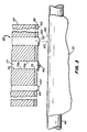
- Figure 2 is a fragmentation view in vertical section of the print head, the print head defining a plurality of channels therein, each channel terminating in an orifice;
- Figure 3 is a fragmentation view in vertical section of the print head, this view showing some of the orifices encrusted with contaminant to be removed ;
- Figure 4 is a view in elevation of a cleaning assembly for removing the contaminant;
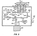
- Figure 5 is a view in vertical section of the cleaning assembly, the cleaning assembly including an oscillating septum disposed opposite the orifice so as to define a gap between the orifice and the septum and also including an ultrasonic transducer for generating pressure waves to remove the contaminant;
- Figure 6 is an enlarged fragmentation view in vertical section of the oscillating septum;
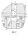
- Figure 7 is an enlarged fragmentation view in vertical section of the cleaning assembly, this view showing the gap having reduced height due to increased length of the oscillating septum, for cleaning contaminant from within the ink channel;
- Figure 8 is an enlarged fragmentation view in vertical section of the cleaning assembly, this view showing the gap having increased width due to increased width of the oscillating septum, for cleaning contaminant from within the ink channel;
- Figure 9 is a view in vertical section of a second embodiment of the invention, wherein the cleaning assembly includes a pressurized gas supply in fluid communication with the gap for introducing gas bubbles into the liquid in the gap; and
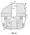
- Figure 10 is an enlarged fragmentation view in vertical section of the second embodiment of the invention;
- Figure 11 is a view in vertical section of a fourth embodiment of the invention, wherein the cleaning assembly includes an expandable septum;
- Figure 12 is an enlarged fragmentation view in vertical section of expandable septum; and
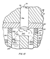
- Figure 13 is a view in vertical section of a fifth embodiment of the invention, wherein the septum is metallic and capable of moving under influence of a magnetic field established by electromagnets.
-
- The present description will be directed in particular to elements forming part of, or cooperating more directly with, apparatus in accordance with the present invention. It is to be understood that elements not specifically shown or described may take various forms well known to those skilled in the art.
- Therefore, referring to Fig. 1, there is shown a self-cleaning printer, generally referred to as 10, for printing an
image 20 on areceiver 30, which may be a reflective-type receiver (e.g., paper) or a transmissive-type receiver (e.g., transparency).Receiver 30 is supported on aplaten roller 40 which is capable of being rotated by aplaten roller motor 50 engagingplaten roller 40. Thus, when platenroller motor 50 rotatesplaten roller 40,receiver 30 will advance in a direction illustrated by afirst arrow 55. - Referring to Figs. 1 and 2,
printer 10 also comprises a "page-width"print head 60 disposed adjacent to platenroller 40.Print head 60 comprises aprint head body 65 having a plurality ofink channels 70, eachchannel 70 terminating in achannel outlet 75. In addition, eachchannel 70, which is adapted to hold anink body 77 therein, is defined by a pair of oppositely disposedparallel side walls head body 65 is acover plate 80 having a plurality oforifices 85 formed therethrough colinearly aligned with respective ones ofchannel outlets 75. Asurface 90 ofcover plate 80 surrounds allorifices 85 and facesreceiver 20. Of course, in order to printimage 20 onreceiver 30, anink droplet 100 must be released fromorifice 85 in direction ofreceiver 20, so thatdroplet 100 is intercepted byreceiver 20. To achieve this result,print head body 65 may be a "piezoelectric ink jet" print head body formed of a piezoelectric material, such as lead zirconium titanate (PZT). Such a piezoelectric material is mechanically responsive to electrical stimuli so thatside walls 79a/b simultaneously inwardly deform when electrically stimulated. Whenside walls 79a/b simultaneously inwardly deform, volume ofchannel 70 decreases to squeezeink droplet 100 fromchannel 70.Ink droplet 100 is preferably ejected along afirst axis 107 normal toorifice 85. Of course, ink is supplied tochannels 70 from anink supply container 109. Also,supply container 109 is preferably pressurized such that ink pressure delivered toprint head 60 is controlled by anink pressure regulator 110. - Still referring to Figs. 1 and 2,
receiver 30 is moved relative to page-width print head 60 by rotation ofplaten roller 40, which is electronically controlled by papertransport control system 120. Papertransport control system 120 is in turn controlled bycontroller 130. Papertransport control system 120 disclosed herein is by way of example only, and many different configurations are possible based on the teachings herein. In the case of page-width print head 60, it is more convenient to movereceiver 30 paststationary head 60.Controller 130, which is connected toplaten roller motor 50,ink pressure regulator 110 and a cleaning assembly, enables the printing and print head cleaning operations. Structure and operation of the cleaning assembly is described in detail hereinbelow.Controller 130 may be a model CompuMotor controller available from Parker Hannifin in Rohrnert Park, California. - Turning now to Fig. 3, it has been observed that
cover plate 80 may become fouled bycontaminant 140.Contaminant 140 may be, for example, an oily film or particulate matter residing onsurface 90.Contaminant 140 also may partially or completely obstructorifice 85. The particulate matter may be, for example, particles of dirt, dust, metal and/or encrustations of dried ink. The oily film may be, for example, grease or the like. Presence ofcontaminant 140 is undesirable because whencontaminant 140 completely obstructsorifice 85,ink droplet 100 is prevented from being ejected fromorifice 85. Also, whencontaminant 140 partially obstructsorifice 85, flight ofink droplet 100 may be diverted fromfirst axis 107 to travel along a second axis 145 (as shown). Ifink droplet 100 travels alongsecond axis 145,ink droplet 100 will land onreceiver 30 in an unintended location. In this manner, such complete or partial obstruction oforifice 85 leads to printing artifacts such as "banding", a highly undesirable result. Also, presence ofcontaminant 140 may alter surface wetting and inhibit proper formation ofdroplet 100. Therefore, it is desirable to clean (i.e., remove)contaminant 140 to avoid printing artifacts. - Therefore, referring to Figs. 1, 4, 5 and 6, a cleaning assembly, generally referred to as 170, is disposed
proximate surface 90 for directing a flow of cleaning liquid alongsurface 90 and acrossorifice 85 to cleancontaminant 140 therefrom.Cleaning assembly 170 is movable from a first or "rest" position 172a spaced-apart fromsurface 90 to asecond position 172b engaging surface 90. This movement is accomplished by means of anelevator 175 coupled tocontroller 130.Cleaning assembly 170 may comprise ahousing 180 for reasons described presently. Disposed inhousing 180 is a generallyrectangular cup 190 having anopen end 195.Cup 190 defines acavity 197 communicating withopen end 195. Attached, such as by a suitable adhesive, to openend 195 is anelastomeric seal 200, which may be rubber or the like, sized to encircle one ormore orifices 85 and sealingly engagesurface 90. Extending alongcavity 197 and oriented perpendicularly oppositeorifices 85 is a structural member, such as an elongateoscillatable septum 210. For reasons provided momentarily,septum 210 is preferably made of a piezoelectric material, such as lead zirconate titanate (PZT). In this regard a mechanical stress is produced in the material when an applied electric field is applied. This mechanical stress will bend (i.e., deform) the material in a preferred direction depending on the direction in which the piezoelectric material is "polled".Septum 210 has anend portion 215 which, when disposedopposite orifice 85, defines agap 220 of predetermined size betweenorifice 85 andend portion 215. Moreover,end portion 215 ofseptum 210 may be disposed opposite a portion ofsurface 90, not includingorifice 85, so thatgap 220 is defined betweensurface 90 andend portion 215. As described in more detail hereinbelow,gap 220 is sized to allow flow of a liquid therethrough in order to cleancontaminant 140 fromsurface 90 and/ororifice 85. In addition, coupled toseptum 210near end portion 215 are a pair oftransducers 218a and 218b for inducing an electric field inend portion 215. In the preferred embodiment of the invention, transducers 218a/b are metal plates capable of conducting electricity, thereby generating the electric field. Thus, to generate the electric field, transducers 218a/b are connected to a suitable power source (not shown). When the electric field is induced inend portion 215, theend portion 215 will bend in a preferred direction (as shown). Although two transducers 218a/b are preferred, there may be only one transducer, if desired. In any event, when two transducers 218a/b are used, the transducers 218a/b are enabled sequentially (i.e., alternately). That is, when transducer 218a is enabled,transducer 218b is not enabled. Conversely, whentransducer 218b is enabled, transducer 218a is not enabled. In this manner, the sequentially enabling transducers 218a/b causes a oscillatory "to-and-fro motion" of the liquid ingap 200. This to-and-fro motion of the liquid in turn causes a "sweeping" action which has been found to increase cleaning effectiveness. By way of example only, not by way of limitation, the frequency of the to-and-fro motion may be between approximately 1Hz and 5 MHz. Also, by way of example only, and not by way of limitation, the velocity of the liquid flowing throughgap 220 may be about 1 to 20 meters per second. Further by way of example only, and not by way of limitation, height ofgap 220 may be approximately 3 to 30 thousandths of an inch. Moreover, hydrodynamic pressure applied tocontaminant 140 ingap 220 due, at least in part, to presence ofseptum 210 may be approximately 1 to 30 psi (pounds per square inch).Septum 210 partitions (i.e., divides)cavity 197 into anfirst chamber 230 and asecond chamber 240, for reasons described more fully hereinbelow. - As best seen in Fig. 5, in communication with the liquid in
cavity 197 is a pressure pulse generator, such as anultrasonic transducer 245, capable of generating a plurality of ultrasonic vibrations and therefore pressure waves 247 in the liquid. Pressure waves 247impact contaminant 140 to dislodgecontaminant 140 fromsurface 90 and/ororifice 85. It is believed pressure waves 247 accomplish this result by adding kinetic energy to the liquid along a vector directed substantially normal to surface 90 andorifices 85. Of course, the liquid is substantially incompressible; therefore, pressure waves 247 propagate in the liquid in order to reachcontaminant 140. By way of example only, and not by way of limitation, pressure waves 247 may have a frequency of approximately 17,000 KHz and above. - Referring again to Fig. 5, interconnecting
first chamber 230 andsecond chamber 240 is a closed-loop piping circuit 250. It will be appreciated that pipingcircuit 250 is in fluid communication withgap 220 for recycling the liquid throughgap 220. In this regard, pipingcircuit 250 comprises afirst piping segment 260 extending fromsecond chamber 240 to areservoir 270 containing a supply of the liquid.Piping circuit 250 further comprises asecond piping segment 280 extending fromreservoir 270 tofirst chamber 230. Disposed insecond piping segment 280 is arecirculation pump 290. Pump 290 pumps the liquid fromreservoir 270, throughsecond piping segment 280, intofirst chamber 230, throughgap 220, intosecond chamber 240, throughfirst piping segment 260 and back toreservoir 270, as illustrated by a plurality ofsecond arrows 295. Disposed infirst piping segment 260 may be afirst filter 300 and disposed insecond piping segment 280 may be asecond filter 310 for filtering (i.e., separating)contaminant 140 from the liquid as the liquid circulates throughpiping circuit 250. It will be appreciated that portions of thepiping circuit 250 adjacent tocup 190 are preferably made of flexible tubing in order to facilitate uninhibited translation ofcup 190 toward and away fromprint head 60, which translation is accomplished by means ofelevator 175. - Still referring to Fig. 5, a
first valve 320 is preferably disposed at a predetermined location infirst piping segment 260, whichfirst valve 320 is operable to block flow of the liquid throughfirst piping segment 260. Also, asecond valve 330 is preferably disposed at a predetermined location insecond piping segment 280, whichsecond valve 330 is operable to block flow of the liquid throughsecond piping segment 280. In this regard,first valve 320 andsecond valve 330 are located infirst piping segment 260 andsecond piping segment 280, respectively, so as to isolatecavity 197 fromreservoir 270, for reasons described momentarily. Athird piping segment 340 has an open end thereof connected tofirst piping segment 260 and another open end thereof received into asump 350. In communication withsump 350 is a suction (i.e., vacuum) pump 360 for reasons described presently.Suction pump 360 drainscup 190 and associated piping of cleaning liquid before cup is detached and returned to first position 172a. Moreover, disposed inthird piping segment 340 is athird valve 370 operable to isolatepiping circuit 250 fromsump 350. - Referring to Figs. 5 and 6, during operation of cleaning
assembly 170,first valve 320 andsecond valve 310 are opened whilethird valve 370 is closed.Recirculation pump 290 is then operated to draw the liquid fromreservoir 270 and intofirst chamber 230. The liquid will then flow throughgap 220. However, as the liquid flows throughgap 220, a hydrodynamic shearing force will be induced in the liquid due to presence ofend portion 215 ofseptum 210. It is believed this shearing force is in turn caused by a hydrodynamic stress forming in the liquid, which stress has a "normal" component δn acting normal to surface 90 (or orifice 85) and a "shear" component τ acting along surface 90 (or across orifice 85). Vectors representing the normal stress component δn and the shear stress component τ are best seen in Fig. 6. The previously mentioned hydrodynamic shearing force and pressure waves 247 act oncontaminant 140 to removecontaminant 140 fromsurface 90 and/ororifice 85, so thatcontaminant 140 becomes entrained in the liquid flowing throughgap 220. In addition,transducers 218a and 218b are alternately enabled to produce the previously mentioned "sweeping" motion ofend portion 215 ofseptum 210. This sweeping motion in turn causes the liquid ingap 220 to move back-and-forth to further loosencontaminant 140. In this manner, cleaning effectiveness is enhanced. Ascontaminant 140 is cleaned fromsurface 90 andorifice 85, the liquid withcontaminant 140 entrained therein, flows intosecond chamber 240 and from there intofirst piping segment 260. Asrecirculation pump 290 continues to operate, the liquid with entrainedcontaminant 140 flows toreservoir 270 from where the liquid is pumped intosecond piping segment 280. However, it is preferable to removecontaminant 140 from the liquid as the liquid is recirculated throughpiping circuit 250. This is preferred in order that contaminant 140 is not redeposited ontosurface 90 and acrossorifice 85. Thus,first filter 300 andsecond filter 310 are provided forfiltering contaminant 140 from the liquid recirculating throughpiping circuit 250. After a desired amount ofcontaminant 140 is cleaned fromsurface 90 and/ororifice 85,recirculation pump 290 is caused to cease operation andfirst valve 320 andsecond valve 330 are closed to isolatecavity 197 fromreservoir 270. At this point,third valve 370 is opened andsuction pump 360 is operated to substantially suction the liquid fromfirst piping segment 260,second piping segment 280 andcavity 197. This suctioned liquid flows intosump 350 for later disposal. However, the liquid flowing intosump 350 is substantially free ofcontaminant 140 due to presence offilters 300/310 and thus may be recycled intoreservoir 270, if desired. - Referring to Figs. 7 and 8, it has been discovered that length and width of
elongate septum 210 controls amount of hydrodynamic stress acting againstsurface 90 andorifice 85. This effect is important in order to control severity of cleaning action. Also, it has been discovered that, whenend portion 215 ofseptum 210 is disposedopposite orifice 85, length and width ofelongate septum 210 controls amount of penetration (as shown) of the liquid intochannel 70. It is believed that control of penetration of the liquid intochannel 70 is in turn a function of the amount of normal stress δn. However, it has been discovered that the amount of normal stress δn is inversely proportional to height ofgap 220. Therefore, normal stress δn, and thus amount of penetration of the liquid intochannel 70, can be increased by increasing length ofseptum 210. Moreover, it has been discovered that amount of normal stress δn is directly proportional to pressure drop in the liquid as the liquid slides alongend portion 215 andsurface 90. Therefore, normal stress δn, and thus amount of penetration of the liquid intochannel 70, can be increased by increasing width ofseptum 210. These effects are important in order to clean anycontaminant 140 which may be adhering to either ofside walls elongate septum 210 is fabricated so that it has a greater than nominal length X, height ofgap 220 is decreased to enhance the cleaning action, if desired. Also, whenelongate septum 210 is fabricated so that it has a greater than nominal width W, the run ofgap 220 is increased to enhance the cleaning action, if desired. Thus, a person of ordinary skill in the art may, without undue experimentation, vary both the length X and width W ofseptum 210 to obtain an optimum gap size for obtaining optimum cleaning depending on the amount and severity of contaminant encrustation. It may be appreciated from the discussion hereinabove, that a height H ofseal 200 also may be varied to vary size ofgap 220 with similar results. - Returning to Fig. 1,
elevator 175 may be connected to cleaningcup 190 for elevatingcup 190 so thatseal 200 sealingly engagessurface 90 whenprint head 60 is atsecond position 172b. To accomplish this result,elevator 175 is connected tocontroller 130, so that operation ofelevator 175 is controlled bycontroller 130. Of course, when the cleaning operation is completed,elevator 175 may be lowered so that seal no longer engagessurface 90. - As best seen in Fig. 1, in order to clean the page-
width print head 60 usingcleaning assembly 170,platen roller 40 has to be moved to make room forcup 190 to engageprint head 60. An electronic signal fromcontroller 130 activates a motorized mechanism (not shown) that movesplaten roller 40 in direction of first double-endedarrow 387 thus making room for upward movement ofcup 190.Controller 130 also controlselevator 175 for transportingcup 190 from first position 172a not engagingprint head 60 tosecond position 172b (shown in phantom) engagingprint head 60. Whencup 190 engages printhead cover plate 80, cleaningassembly 170 circulates liquid through cleaningcup 190 and over printhead cover plate 80. Whenprint head 60 is required for printing,cup 190 is retracted intohousing 180 byelevator 175 to its resting first position 172a. Thecup 190 may be advanced outwardly from and retracted inwardly intohousing 180 in direction of second double-endedarrow 388. - Still referring to Fig. 1, the liquid emerging from
outlet chamber 240 initially will be contaminated withcontaminant 140. It is desirable to collect this liquid insump 350 rather than to recirculate the liquid. Therefore, this contaminated liquid is directed tosump 350 by closingsecond valve 330 and openingthird valve 370 whilesuction pump 360 operates. The liquid will then be free ofcontaminant 140 and may be recirculated by closingthird valve 370 and openingsecond valve 330. Adetector 397 is disposed infirst piping segment 260 to determine when the liquid is clean enough to be recirculated. Information fromdetector 397 can be processed and used to activate the valves in order to direct exiting liquid either intosump 350 or into recirculation. In this regard,detector 397 may be a spectrophotometric detector. In any event, at the end of the cleaning procedure,suction pump 360 is activated andthird valve 370 is opened to suction intosump 350 any trapped liquid remaining betweensecond valve 330 andfirst valve 320. This process prevents spillage of liquid when cleaningassembly 170 is detached fromcover plate 80. Further, this process causescover plate 80 to be substantially dry, thereby permittingprint head 60 to function without impedance from cleaning liquid drops being aroundorifices 85. To resume printing,sixth valve 430 is closed andfifth valve 420 is opened toprime channel 70 with ink.Suction pump 360 is again activated, andthird valve 370 is opened to suction any liquid remaining incup 190. Alternatively, thecup 190 may be detached and a separate spittoon (not shown) may be brought into alignment withprint head 60 to collect drops of ink that are ejected fromchannel 70 during priming ofprint head 60. - The mechanical arrangement described above is but one example. Many different configurations are possible. For example,
print head 60 may be rotated outwardly about ahorizontal axis 389 to a convenient position to provide clearance forcup 190 to engage printhead cover plate 80. - Referring to Figs. 9 and 10, there is shown a second embodiment of the present invention. In this second embodiment of the invention, a
pressurized gas supply 390 is in communication withgap 220 for injecting a pressurized gas intogap 220. The gas will form a multiplicity of gas bubbles 395 in the liquid to enhance cleaning ofcontaminant 140 fromsurface 90 and/ororifice 85. - Referring to Figs. 11 and 12, there is shown a fourth embodiment of the present invention. In this fourth embodiment of the invention,
elongate septum 210 has abore 420 longitudinally therein. In thisseptum 210 is preferably made of an elastomeric piezoelectric material, such as a rubber and PZT composition. Coupled to bore 420 is apneumatic pump 430 for pumping a gas (e.g., air) intobore 420. As the gas is pumped intobore 420,elastic septum 210 is pressurized so thatseptum 210 expands to greater width W and greater length X to obtain the enhanced cleaning effect described hereinabove. In this manner,septum 210 is expandable from a first volume thereof to a second volume greater than the first volume. Moreover, ableed valve 440 is preferably provided. Bleedvalve 440 is closed whilepump 430 operates to expandelastic septum 210. After the desired cleaning is achieved, pump 430 is caused to cease operation and bleedvalve 440 is opened to release the gas frombore 420. As the gas is released frombore 420,septum 210 will return to its initial first volume. - Referring to Fig. 13, there is shown a fifth embodiment of the present invention. In this fifth embodiment of the invention,
septum 210 is formed of a metallic material so thatseptum 210 is movable under influence of a magnetic field. A pair of opposing electromagnets 450a/b are attached to an inside wall ofcavity 197near end portion 215 ofseptum 210. Magnets 450a/b are sequentially enabled to sequentially generate an magnetic field acting onend portion 215 ofseptum 210. As eachmagnet 450a or 450b is enabled,end portion 215 will be drawn to the magnet in order to obtain the previously mentioned "sweeping" motion ofend portion 215. Of course, this sweeping motion enhances cleaning effectiveness, as previously described. - The cleaning liquid may be any suitable liquid solvent composition, such as water, isopropanol, diethylene glycol, diethylene glycol monobutyl ether, octane, acids and bases, surfactant solutions and any combination thereof. when partially or completely blocked
channels 70 attempt to ejectink droplets 100. Such a contamination sensor may also be a flow detector in communication with ink inchannels 70 to detect low ink flow when partially or completely blockedchannels 70 attempt to ejectink droplets 100. Such a contamination sensor may also be an optical detector in optical communication withsurface 90 andorifices 85 to optically detect presence ofcontaminant 140 by means of reflection or emissivity. Such a contamination sensor may also be a device measuring amount of ink released into a spittoon-like container during predetermined periodic purging ofchannels 70. In this case, the amount of ink released into the spittoon-like container would be measured by the device and compared against a known amount of ink that should be present in the spittoon-like container if no orifices were blocked bycontaminant 140. Moreover,controller 130 may drive other auxiliary functions. - Therefore, what is provided is a self-cleaning printer with oscillating septum and ultrasonics and method of operating the printer. Complex liquid compositions may also be used, such as microemulsions, micellar surfactant solutions, vesicles and solid particles dispersed in the liquid.
- It may be appreciated from the description hereinabove, that an advantage of the present invention is that cleaning
assembly 170 cleans contaminant 140 fromsurface 90 and/ororifice 85 without use of brushes or wipers which might otherwise damagesurface 90 and/ororifice 85. This is so becauseseptum 210 induces shear stress in the liquid that flows throughgap 220 to cleancontaminant 140 fromsurface 90 and/ororifice 85. - It may be appreciated from the description hereinabove, that another advantage of the present invention is that cleaning efficiency is increased. This is so because operation of oscillating transducers 218a/b induce to-and-fro motion of the cleaning fluid in the gap, thereby agitating the liquid coming into contact with
contaminant 140. Agitation of the liquid in this manner in turn agitatescontaminant 140 in order to loosencontaminant 140. - While the invention has been described with particular reference to its preferred embodiments, it will be understood by those skilled in the art that various changes may be made and equivalents may be substituted for elements of the preferred embodiments without departing from the invention as disclosed in claims 1 and 4. In addition, many modifications may be made to adapt a particular situation and material to a teaching of the present invention without departing from the essential teachings of the invention. For example, a heater may be disposed in
reservoir 270 to heat the liquid therein for enhancing cleaning ofsurface 90,channel 70 and/ororifice 85. This is particularly useful when the cleaning liquid is of a type that increases in cleaning effectiveness as temperature of the liquid is increased. As another example, in the case of a multiple color printer having a plurality of print heads corresponding to respective ones of a plurality of colors, one or more dedicated cleaning assemblies per color might be used to avoid cross-contamination of print heads by inks of different colors. As yet another example, a contamination sensor may be connected to cleaningassembly 170 for detecting when cleaning is needed. In this regard, such a contamination sensor may a pressure transducer in fluid communication with ink inchannels 70 for detecting rise in ink back pressure
Claims (6)
- A self-cleaning inkjet printer, comprising:characterized by a septum disposed in the cavity and extending towards the surface to form a gap (220) between an end portion (215) of the septum and the nozzle opening, the gap being between 0.076 mm and 0.76 mm in spacing and, the septum forming a partition to divide the cavity into a first chamber (230) and a second chamber (240), and the septum being made of piezoelectric material;a print head (60) having a surface (90) thereon, the surface including a nozzle opening;a cleaning assembly positionable to clean the surface, the cleaning assembly including a cup (190) defining a cavity (197) and having an open end (195), the cup including a seal that sealingly engages the surface (90) at the open end (195) and about the nozzle opening, the cleaning assembly including a pump (290) for moving a liquid in the cavity and an ultrasonic first transducer means (245) for generating pressure waves in the liquid in the cavity to dislodge contaminant from the surface (90) and the nozzle opening;the pump being operative to pump liquid into the first chamber (230), through the gap (220) and into the second chamber (240) so as to induce a hydrodynamic shearing force in the liquid flowing through the gap; andsecond transducer means (218a, 218b) coupled to the septum to vibrate the septum to produce a sweeping motion of an end portion of the septum so that the septum causes the liquid in the gap (220) to move back-and-forth to further loosen contaminant on the surface.
- The self-cleaning printer of claim 1 wherein the second transducer means comprises a plurality of transducers coupled to the septum for oscillating the septum.
- The self-cleaning printer of claim 1 or 2 and further comprising a gas supply (390) in liquid communication with the gap for injecting a gas into the liquid to form gas bubbles (395) in the flowing liquid for enhancing cleaning of the surface.
- A method of operating a self-cleaning printer, comprising:characterized by providing a septum disposed in the cavity and extending towards the surface to form a gap between an end portion of the septum and the nozzle opening, the gap being between 0.076 mm and 0.76 mm in spacing, the septum forming a partition to divide the cavity into a first chamber and a second chamber; operating the pump to pump the liquid into the first chamber, through the gap and into the second chamber so as to induce a hydrodynamic shearing force in the liquid flowing through the gap; andproviding a print head having a surface thereon, the surface including a nozzle opening;positioning a cleaning assembly including a cup defining a cavity having an open end so that the cup sealingly engages the surface so that the open end is positioned about the nozzle opening;operating a pump to move liquid in the cavity;energizing an ultrasonic first transducer means to generate pressure waves in the liquid in the cavity to dislodge contaminant from the surface and the nozzle opening;
wherein the septum is made of a piezoelectric material and is induced to vibrate by operation of a second transducer means coupled to the septum so that vibration of the septum causes the liquid in the gap to move back-and-forth to further loosen contaminant on the surface. - The method of claim 4, wherein the liquid is caused to flow along a surface of said septum in a direction towards the surface that includes the nozzle opening and then the direction of the flow of the liquid is changed to flow through the gap between the septum and the surface that includes the nozzle opening.
- The method of claim 4 or 5, further comprising injecting a gas into the liquid to form gas bubbles in the liquid for enhancing cleaning of the surface.
Applications Claiming Priority (2)
| Application Number | Priority Date | Filing Date | Title |
|---|---|---|---|
| US222409 | 1998-12-29 | ||
| US09/222,409 US6286929B1 (en) | 1998-12-29 | 1998-12-29 | Self-cleaning ink jet printer with oscillating septum and ultrasonics and method of assembling the printer |
Publications (2)
| Publication Number | Publication Date |
|---|---|
| EP1016531A1 EP1016531A1 (en) | 2000-07-05 |
| EP1016531B1 true EP1016531B1 (en) | 2003-09-17 |
Family
ID=22832062
Family Applications (1)
| Application Number | Title | Priority Date | Filing Date |
|---|---|---|---|
| EP99204276A Expired - Lifetime EP1016531B1 (en) | 1998-12-29 | 1999-12-13 | A self-cleaning ink jet printer with oscillating septum and method of operating the printer |
Country Status (4)
| Country | Link |
|---|---|
| US (1) | US6286929B1 (en) |
| EP (1) | EP1016531B1 (en) |
| JP (1) | JP2000229416A (en) |
| DE (1) | DE69911365T2 (en) |
Families Citing this family (17)
| Publication number | Priority date | Publication date | Assignee | Title |
|---|---|---|---|---|
| US6007318A (en) | 1996-12-20 | 1999-12-28 | Z Corporation | Method and apparatus for prototyping a three-dimensional object |
| KR100431007B1 (en) * | 2001-12-03 | 2004-05-12 | 삼성전자주식회사 | maintenance apparatus of an ink-jet printer having a vaporizer |
| US6660103B1 (en) | 2002-03-28 | 2003-12-09 | Vutek, Inc. | Cleaning process for ink jet printheads |
| US7178897B2 (en) * | 2004-09-15 | 2007-02-20 | Eastman Kodak Company | Method for removing liquid in the gap of a printhead |
| KR101298564B1 (en) * | 2005-05-06 | 2013-08-22 | 디터 부르쯔 | Spray nozzle, spray device and the operation method thereof |
| JP4867472B2 (en) * | 2006-05-25 | 2012-02-01 | 凸版印刷株式会社 | Micro dispenser type color correction device |
| US7971991B2 (en) | 2006-05-26 | 2011-07-05 | Z Corporation | Apparatus and methods for handling materials in a 3-D printer |
| JP4864617B2 (en) * | 2006-09-21 | 2012-02-01 | 株式会社東芝 | Cleaning liquid and nozzle plate cleaning method |
| KR20080112541A (en) * | 2007-06-21 | 2008-12-26 | 삼성전자주식회사 | Print-head cleaning device and ink-jet type image forming apparatus having the same |
| US8113613B2 (en) * | 2008-05-01 | 2012-02-14 | Videojet Technologies Inc. | System and method for maintaining or recovering nozzle function for an inkjet printhead |
| KR100986804B1 (en) * | 2008-05-21 | 2010-10-08 | 한양대학교 산학협력단 | Apparatus to remove blocking in single nozzle head |
| ES2492090B1 (en) * | 2013-02-08 | 2015-07-07 | Personas Y Tecnologia, S.L. | EQUIPMENT AND METHOD FOR CLEANING INK INJECTION PRINT HEADS |
| US9090113B1 (en) * | 2014-03-31 | 2015-07-28 | Xerox Corporation | System for detecting inoperative ejectors in three-dimensional object printing using a pneumatic sensor |
| US9869227B2 (en) * | 2015-05-26 | 2018-01-16 | Intellectual Reserves, LLC | System and method for repeatable fluid measurements |
| CN106004044B (en) * | 2016-05-11 | 2017-12-22 | 京东方科技集团股份有限公司 | Ink measuring system and printing device |
| KR102573601B1 (en) * | 2020-08-06 | 2023-09-01 | 세메스 주식회사 | Head cleaning unit and apparatus for treating substrate including the same |
| CN114589071B (en) * | 2022-04-04 | 2022-12-13 | 南通市通州忠义纺织机械有限公司 | Novel backflow device for coating machine |
Family Cites Families (33)
| Publication number | Priority date | Publication date | Assignee | Title |
|---|---|---|---|---|
| US3373437A (en) | 1964-03-25 | 1968-03-12 | Richard G. Sweet | Fluid droplet recorder with a plurality of jets |
| GB1143079A (en) | 1965-10-08 | 1969-02-19 | Hertz Carl H | Improvements in or relating to recording devices for converting electrical signals |
| US3903034A (en) | 1970-12-07 | 1975-09-02 | Dick Co Ab | Offset jet printing ink |
| US3705043A (en) | 1970-12-07 | 1972-12-05 | Dick Co Ab | Infrared absorptive jet printing ink composition |
| US3846141A (en) | 1970-12-07 | 1974-11-05 | Dick Co Ab | Jet printing ink composition |
| US3776642A (en) | 1972-08-01 | 1973-12-04 | Dickey John Corp | Grain analysis computer |
| DE2258835A1 (en) | 1972-12-01 | 1974-06-12 | Agfa Gevaert Ag | Aqueous INK FOR THE INK JET PROCESS |
| US3870528A (en) | 1973-12-17 | 1975-03-11 | Ibm | Infrared and visible dual dye jet printer ink |
| US3878519A (en) | 1974-01-31 | 1975-04-15 | Ibm | Method and apparatus for synchronizing droplet formation in a liquid stream |
| CA1158706A (en) | 1979-12-07 | 1983-12-13 | Carl H. Hertz | Method and apparatus for controlling the electric charge on droplets and ink jet recorder incorporating the same |
| US4354197A (en) * | 1980-10-03 | 1982-10-12 | Ncr Corporation | Ink jet printer drive means |
| US4600928A (en) | 1985-04-12 | 1986-07-15 | Eastman Kodak Company | Ink jet printing apparatus having ultrasonic print head cleaning system |
| US4591870A (en) | 1985-04-12 | 1986-05-27 | Eastman Kodak Company | Ink jet printing apparatus and method with condensate-washing for print head |
| JPS62113555A (en) | 1985-11-13 | 1987-05-25 | Canon Inc | Ink jet recorder |
| JPS63242643A (en) * | 1987-03-31 | 1988-10-07 | Canon Inc | Liquid jet recorder |
| EP0292779A1 (en) | 1987-05-25 | 1988-11-30 | Siemens Aktiengesellschaft | Method and device for cleaning elements with cavities |
| US4849769A (en) | 1987-06-02 | 1989-07-18 | Burlington Industries, Inc. | System for ultrasonic cleaning of ink jet orifices |
| US5148746A (en) | 1988-08-19 | 1992-09-22 | Presstek, Inc. | Print-head and plate-cleaning assembly |
| US4970535A (en) | 1988-09-26 | 1990-11-13 | Tektronix, Inc. | Ink jet print head face cleaner |
| JPH02235764A (en) * | 1989-03-10 | 1990-09-18 | Canon Inc | Ink jet recorder |
| US5115250A (en) | 1990-01-12 | 1992-05-19 | Hewlett-Packard Company | Wiper for ink-jet printhead |
| US5305015A (en) | 1990-08-16 | 1994-04-19 | Hewlett-Packard Company | Laser ablated nozzle member for inkjet printhead |
| JP3175366B2 (en) | 1992-12-01 | 2001-06-11 | 富士ゼロックス株式会社 | Inkjet recording ink |
| US5325111A (en) * | 1992-12-28 | 1994-06-28 | Xerox Corporation | Removing waste ink from capping station |
| US5350616A (en) | 1993-06-16 | 1994-09-27 | Hewlett-Packard Company | Composite orifice plate for ink jet printer and method for the manufacture thereof |
| US5426458A (en) | 1993-08-09 | 1995-06-20 | Hewlett-Packard Corporation | Poly-p-xylylene films as an orifice plate coating |
| US5412441A (en) * | 1994-03-07 | 1995-05-02 | Tibbling; Lars | Keratometer device having photographically produced bore pattern |
| US5559538A (en) * | 1994-08-12 | 1996-09-24 | Hewlett-Packard Company | Positioning of service station and paper pick pressure plate using single motor |
| US5574485A (en) | 1994-10-13 | 1996-11-12 | Xerox Corporation | Ultrasonic liquid wiper for ink jet printhead maintenance |
| US5774140A (en) | 1995-10-31 | 1998-06-30 | Hewlett-Packard Company | Skip stroke wiping system for inkjet printheads |
| US5738716A (en) | 1996-08-20 | 1998-04-14 | Eastman Kodak Company | Color pigmented ink jet ink set |
| US5725647A (en) | 1996-11-27 | 1998-03-10 | Minnesota Mining And Manufacturing Company | Pigmented inks and humectants used therewith |
| US5997127A (en) * | 1998-09-24 | 1999-12-07 | Eastman Kodak Company | Adjustable vane used in cleaning orifices in inkjet printing apparatus |
-
1998
- 1998-12-29 US US09/222,409 patent/US6286929B1/en not_active Expired - Lifetime
-
1999
- 1999-12-13 DE DE69911365T patent/DE69911365T2/en not_active Expired - Fee Related
- 1999-12-13 EP EP99204276A patent/EP1016531B1/en not_active Expired - Lifetime
- 1999-12-24 JP JP11368418A patent/JP2000229416A/en active Pending
Also Published As
| Publication number | Publication date |
|---|---|
| DE69911365D1 (en) | 2003-10-23 |
| JP2000229416A (en) | 2000-08-22 |
| DE69911365T2 (en) | 2004-07-22 |
| US6286929B1 (en) | 2001-09-11 |
| EP1016531A1 (en) | 2000-07-05 |
Similar Documents
| Publication | Publication Date | Title |
|---|---|---|
| EP1005997B1 (en) | A self-cleaning ink jet printer with reverse flow and method of assembling the printer | |
| US6350007B1 (en) | Self-cleaning ink jet printer using ultrasonics and method of assembling same | |
| EP1088665B1 (en) | A self-cleaning ink jet printer system with a reversible fluid flow and a rotating roller and method of assembling the printer system | |
| EP1088664B1 (en) | A self-cleaning ink jet printer system with a reversible fluid flow and a method of assembling the printer system | |
| US6513903B2 (en) | Ink jet print head with capillary flow cleaning | |
| EP1016531B1 (en) | A self-cleaning ink jet printer with oscillating septum and method of operating the printer | |
| US6183057B1 (en) | Self-cleaning ink jet printer having ultrasonics with reverse flow and method of assembling same | |
| EP1060894B1 (en) | Multi-fluidic cleaning for ink jet print heads | |
| US6595617B2 (en) | Self-cleaning printer and print head and method for manufacturing same | |
| EP1016530B1 (en) | A self-cleaning ink jet printer with oscillating septum and method of assembling the printer | |
| US6283575B1 (en) | Ink printing head with gutter cleaning structure and method of assembling the printer | |
| EP1262324A1 (en) | Ink jet print head with cross-flow cleaning | |
| US6497472B2 (en) | Self-cleaning ink jet printer and print head with cleaning fluid flow system | |
| EP1016529A1 (en) | An ink jet printer with cleaning mechanism having a wiper blade and transducer and method of assembling the printer | |
| US6145952A (en) | Self-cleaning ink jet printer and method of assembling same | |
| EP1170130B1 (en) | Cleaning assembly for cleaning an ink jet print head in a self-cleaning ink jet printer system |
Legal Events
| Date | Code | Title | Description |
|---|---|---|---|
| PUAI | Public reference made under article 153(3) epc to a published international application that has entered the european phase |
Free format text: ORIGINAL CODE: 0009012 |
|
| AK | Designated contracting states |
Kind code of ref document: A1 Designated state(s): DE FR GB |
|
| AX | Request for extension of the european patent |
Free format text: AL;LT;LV;MK;RO;SI |
|
| 17P | Request for examination filed |
Effective date: 20001207 |
|
| AKX | Designation fees paid |
Free format text: DE FR GB |
|
| 17Q | First examination report despatched |
Effective date: 20011112 |
|
| GRAH | Despatch of communication of intention to grant a patent |
Free format text: ORIGINAL CODE: EPIDOS IGRA |
|
| RTI1 | Title (correction) |
Free format text: A SELF-CLEANING INK JET PRINTER WITH OSCILLATING SEPTUM AND METHOD OF OPERATING THE PRINTER |
|
| GRAH | Despatch of communication of intention to grant a patent |
Free format text: ORIGINAL CODE: EPIDOS IGRA |
|
| GRAA | (expected) grant |
Free format text: ORIGINAL CODE: 0009210 |
|
| AK | Designated contracting states |
Kind code of ref document: B1 Designated state(s): DE FR GB |
|
| REG | Reference to a national code |
Ref country code: GB Ref legal event code: FG4D |
|
| REF | Corresponds to: |
Ref document number: 69911365 Country of ref document: DE Date of ref document: 20031023 Kind code of ref document: P |
|
| ET | Fr: translation filed | ||
| PLBE | No opposition filed within time limit |
Free format text: ORIGINAL CODE: 0009261 |
|
| STAA | Information on the status of an ep patent application or granted ep patent |
Free format text: STATUS: NO OPPOSITION FILED WITHIN TIME LIMIT |
|
| 26N | No opposition filed |
Effective date: 20040618 |
|
| PGFP | Annual fee paid to national office [announced via postgrant information from national office to epo] |
Ref country code: GB Payment date: 20061106 Year of fee payment: 8 |
|
| PGFP | Annual fee paid to national office [announced via postgrant information from national office to epo] |
Ref country code: FR Payment date: 20061201 Year of fee payment: 8 |
|
| PGFP | Annual fee paid to national office [announced via postgrant information from national office to epo] |
Ref country code: DE Payment date: 20061229 Year of fee payment: 8 |
|
| GBPC | Gb: european patent ceased through non-payment of renewal fee |
Effective date: 20071213 |
|
| PG25 | Lapsed in a contracting state [announced via postgrant information from national office to epo] |
Ref country code: DE Free format text: LAPSE BECAUSE OF NON-PAYMENT OF DUE FEES Effective date: 20080701 |
|
| REG | Reference to a national code |
Ref country code: FR Ref legal event code: ST Effective date: 20081020 |
|
| PG25 | Lapsed in a contracting state [announced via postgrant information from national office to epo] |
Ref country code: GB Free format text: LAPSE BECAUSE OF NON-PAYMENT OF DUE FEES Effective date: 20071213 |
|
| PG25 | Lapsed in a contracting state [announced via postgrant information from national office to epo] |
Ref country code: FR Free format text: LAPSE BECAUSE OF NON-PAYMENT OF DUE FEES Effective date: 20071231 |