EP0988872A1 - Plug device for generating bio-positive waves - Google Patents
Plug device for generating bio-positive waves Download PDFInfo
- Publication number
- EP0988872A1 EP0988872A1 EP98117863A EP98117863A EP0988872A1 EP 0988872 A1 EP0988872 A1 EP 0988872A1 EP 98117863 A EP98117863 A EP 98117863A EP 98117863 A EP98117863 A EP 98117863A EP 0988872 A1 EP0988872 A1 EP 0988872A1
- Authority
- EP
- European Patent Office
- Prior art keywords
- winding
- generator device
- phase lines
- plug generator
- conductor
- Prior art date
- Legal status (The legal status is an assumption and is not a legal conclusion. Google has not performed a legal analysis and makes no representation as to the accuracy of the status listed.)
- Granted
Links
Images
Classifications
-
- A—HUMAN NECESSITIES
- A61—MEDICAL OR VETERINARY SCIENCE; HYGIENE
- A61N—ELECTROTHERAPY; MAGNETOTHERAPY; RADIATION THERAPY; ULTRASOUND THERAPY
- A61N1/00—Electrotherapy; Circuits therefor
- A61N1/16—Screening or neutralising undesirable influences from or using, atmospheric or terrestrial radiation or fields
Definitions
- the present invention relates to a shield or information connector as an effective device without its own electricity for radiating a biopositive active energy on in particular electrical cables for the purpose of interference suppression and / or dissolving the electrical lines or harmful radiation emanating from other lines.
- the connector generator device with the Features of claim 1 points over the known approach the advantage that the harmful electromagnetic Alternating field of a current-carrying conductor is more reliable is shielded than was previously possible, whereby without a mineral to support the shielding effect can be.
- the shielding winding consists of a double winding from a wire folded in the middle, which in turn insulates or may not be isolated.
- the shielding winding consists of a double winding from a wire folded in the middle, which in turn insulates or may not be isolated.
- the individual turns directly against each other are equidistant, and the plane described by a turn lies essentially perpendicular to the direction of the current or the current Ladder.
- the bioenergetically effective Effect on the circuit optimized.
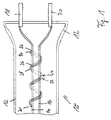
- Fig. 1 shows a schematic representation of the essential Components of the connector generator device according to the invention.
- reference numeral 10 denotes the invention Plug generator device as a whole, 12 its housing, 14, 16 phase lines of the AC network, 18, 20 to the Pole pins belonging to phase lines, 22, 24 a double winding, which consists of a wire. This will be in the middle folded and then clockwise over the two electrical ones Phase lines in the direction of the pole pins in uniform Coils wound.
- the connector generator device according to the invention which as Whole is designated by the reference number 10, contains in essentially a conventional housing 12 as a mechanical cover the electromagnetic inside effective parts. On the one hand, they are at least two electrical ones Phase lines 14, 16 for coupling to the AC network.
- the ground line is not shown in the figure because the device also in power systems without this ground wire is effective. However, it also works in modern, three-phase systems.
- phase lines 14, 16 are in a conventional manner from one another isolated by a plastic sheathing and flow into the associated pole pins 18, 20, which are for insertion into a conventional Power outlet.
- a double winding 22, 24 made by an insulating Sheathing metal wire 26 or 28 insulated from the outside.
- the folding of the winding 30 is closed. In the drawing the windings consist of 5 turns each, however not drawn close together for clarity are.
- the windings are preferably close to one another arranged close and equidistant, and the individual Wires must not touch if they are on an insulating one Sheathing the winding wires - here for clarity also not shown - is waived.
- the turns preferably run in each case such that the through a complete turn approximately described area perpendicular to the area surrounded by it Power line runs. That is, those connected to the network Power lines penetrate this level almost vertically.
- the double winding preferably contains at least eight full turns and is in close proximity to the End of the phase line 14, 16 led into the poles.
- the double winding should be so tight that it can not be easily moved on the phase lines.
- the double winding described in this way acts as a so-called scalar antenna, which is the alternating electromagnetic field of the phase lines takes up, in turn, its own induced Alternating field builds up and this back into the inside impressed phase lines.
- This, from the double winding outgoing effect on the phase lines is on the entire circuit in the direction of one at the connector generator device connected electrical consumer such as. a lamp, a computer, etc.
- the preferred bifilar winding lifts in particular (Double winding) the left-polarized mentioned above Vibrations in their harmful effects on humans and animals and plant in a special way.
- the one shown in FIG. 1 can be shown schematically Double winding also via fuel lines, oil lines, Filling lines for beer, water, milk and others Drinks and on filling lines of pasty, free-flowing and granular media (fabrics) used to a bio-positive active energy in the interior of each Radiate line.
- Double winding also via fuel lines, oil lines, Filling lines for beer, water, milk and others Drinks and on filling lines of pasty, free-flowing and granular media (fabrics) used to a bio-positive active energy in the interior of each Radiate line.
- the number of turns and the spacing of the turns vary from one another depending on the application.
- the winding described above can also have a metal core (different metals; angular, round or oval), different polished rock types (angular, round or oval), a pipe (different pipes with or without Flow and of different material; angular, round or oval) can be used.
- a metal core different metals; angular, round or oval
- different polished rock types angular, round or oval
- a pipe different pipes with or without Flow and of different material; angular, round or oval
Abstract
Description
Die vorliegende Erfindung betrifft einen Abschirm- bzw. Informationsstecker als ohne eigene Stromenergie wirksames Gerät zum Abstrahlen einer biopositiven Wirkenergie auf insbesondere elektrische Leitungen zum Zwecke des Entstörens und/oder Auflösens der von den elektrischen Leitungen oder anderen Leitungen ausgehenden schädlichen Strahlungen.The present invention relates to a shield or information connector as an effective device without its own electricity for radiating a biopositive active energy on in particular electrical cables for the purpose of interference suppression and / or dissolving the electrical lines or harmful radiation emanating from other lines.
Der Mensch lebt als feinsinniges, allen möglichen Umwelteinflüssen unterworfenes Wesen in immer zunehmenderem Maße in einer Umgebung, in der es sehr viele Stromleitungen, die mit Wechselstrom gespeist sind, gibt. Es ist bekannt, daß ein mit Wechselstrom durchflossener Leiter ein elektromagnetisches Wechselfeld nach außen abgibt, dessen Wirkung auf den Menschen je nach Intensität durchaus gesundheitsschädlich sein kann. Denn jede elektrische Welle hat eine Polarisation. Dabei weist der Wechselstrom mit seiner Frequenz von 50 Hz, 50 rechtspolarisierte und 50 linkspolarisierte Schwingungen pro Sekunde auf. Dabei werden die 50 linkspolarisierten Schwingungen nach einschlägigen Erfahrungsberichten von Mensch, Tier und Pflanze nicht vertragen, die rechtspolarisierten Schwingungen jedoch schon.Man lives as subtle, all possible environmental influences subject in ever increasing measure in an environment in which there are very many power lines with AC are fed there. It is known that a with AC current through an electromagnetic Alternating field gives out, its effect on humans depending on the intensity, may be harmful to health can. Because every electrical wave has a polarization. Here the alternating current has a frequency of 50 Hz, 50 right polarized and 50 left polarized vibrations per Second on. The 50 left polarized vibrations according to relevant human experience reports, Animal and plant not tolerated, the right polarized However, vibrations.
Die der vorliegenden Erfindung zugrunde liegende Problematik besteht also allgemein darin, die Wirkung dieser schädlichen Abstrahlungen auf den Menschen oder auf seine Haustiere zu vermindern. Aus dem deutschen Gebrauchsmuster 29 5020 54 ist ein Abschirm- bzw. Informationsstecker bekannt, der ähnlichen Zwecken dienen soll. Der dort vorgeschlagene Abschirmstecker besitzt eine gewisse Abschirmwirkung, die jedoch zu gering ausgebildet ist. Des weiteren benötigt er noch ein sogenanntes Mineralelement, das als Speicher für Informationen (Schwingungsfrequenzen) vorhanden sein muß, um eine gewisse Wirkung zu gewährleisten.The problem underlying the present invention So generally, the effect of this is harmful Radiations on people or on their pets Reduce. From the German utility model 29 5020 54 is a shielding or information connector known, the similar To serve purposes. The shield connector proposed there has a certain shielding effect, but too little is trained. He also needs a so-called Mineral element used as a store for information (Vibration frequencies) must be present to a certain Ensure effect.
Als nachteilhaft bei dem obigen bekannten Ansatz hat sich neben den Abschirmwirkungen die Tatsache herausgestellt, daß das Aufstellen und Einbringen eines solchen Minerals nicht in allen Anwendungsfällen zweckdienlich ist, sowie die Abschirmwirkung in unnötiger Weise verteuert.A disadvantage of the above known approach has also been found the shielding effects highlighted the fact that the installation and introduction of such a mineral not in is useful for all applications, as well as the shielding effect unnecessarily expensive.
Die erfindungsgemäße Steckergenerator-Vorrichtung mit den
Merkmalen des Anspruchs 1 weist gegenüber dem bekannten Lösungsansatz
den Vorteil auf, daß das schädliche elektromagnetische
Wechselfeld eines stromdurchflossenen Leiters zuverlässiger
abgeschirmt wird, als es bisher möglich war, wobei
auf ein Mineral zur Unterstützung der Abschirmwirkung verzichtet
werden kann.The connector generator device according to the invention with the
Features of
Die der vorliegenden Erfindung zugrunde liegende Idee besteht darin, einen oder zwei wechselstromführende Leiter mit einer Wicklung aus wenigstens einem, vorzugsweise in der Mitte gefalteten Leiter zu umgeben, wodurch ein eigenes, sekundäres elektromagnetisches Feld erzeugt wird, das bestimmte, bioenergetisch wirksame Wirkungen auf den Stromkreislauf überträgt. Diese vorteilhafte Wirkung pflanzt sich dann im Leiter in Richtung des elektrischen Verbrauchers im Haushalt oder am Arbeitsplatz oder dergleichen fort. Daher sind der Mensch, Pflanzen oder Tiere nicht mehr der schädlichen Abstrahlung aus allen stromdurchflossenen Leitern und Verbrauchern ausgesetzt.The idea on which the present invention is based exists therein, one or two AC conductors with one Winding from at least one, preferably folded in the middle Surround the ladder, creating its own secondary electromagnetic field is generated that certain, bioenergetic transmits effective effects on the circuit. This beneficial effect is then planted in the ladder towards the electrical consumer in the household or on Workplace or the like. Therefore, man Plants or animals are no longer harmful radiation exposed from all current-carrying conductors and consumers.
In den Unteransprüchen finden sich vorteilhafte Weiterbildungen
und Verbesserungen der in Anspruch 1 angegebenen Steckergenerator-Vorrichtung.
Gemäß einer bevorzugten Weiterbildung
besteht die abschirmende Wicklung aus einer Doppelwicklung
von einem in der Mitte gefalteten Draht, die ihrerseits isoliert
oder auch nicht isoliert sein kann. Hierbei wird eine
besonders gute Abschirmwirkung erzielt.Advantageous further developments can be found in the subclaims
and improvements to the connector generator device specified in
Gemäß einer weiteren bevorzugten Weiterbildung liegen die einzelnen Windungen aneinander direkt an, sind äquidistant, und die durch eine Windung beschriebene Ebene liegt im wesentlichen senkrecht zur Richtung des oder der stromdurchflossenen Leiter. Hierbei wird die bioenergetisch wirksame Wirkung auf den Stromkreislauf optimiert.According to a further preferred development, the individual turns directly against each other, are equidistant, and the plane described by a turn lies essentially perpendicular to the direction of the current or the current Ladder. Here the bioenergetically effective Effect on the circuit optimized.
Ein Ausführungsbeispiel der Erfindung ist in der Zeichnung dargestellt und wird in der nachfolgenden Beschreibung näher erläutert.An embodiment of the invention is in the drawing shown and is described in more detail in the following description explained.
Dabei zeigt:
- Fig.1
- eine schematische Darstellung der wesentlichen Komponenten der erfindungsgemäßen Steckergenerator-Vorrichtung.
- Fig. 1
- is a schematic representation of the essential components of the connector generator device according to the invention.
Fig. 1 zeigt eine schematische Darstellung der wesentlichen Komponenten der erfindungsgemäßen Steckergenerator-Vorrichtung.Fig. 1 shows a schematic representation of the essential Components of the connector generator device according to the invention.
In Fig. 1 bezeichnet Bezugszeichen 10 die erfindungsgemäße
Steckergenerator-Vorrichtung als Ganzes, 12 ihr Gehäuse, 14,
16 Phasenleitungen des Wechselstromnetzes, 18, 20 die zu den
Phasenleitungen gehörenden Polstifte, 22, 24 eine Doppelwicklung,
die aus einem Draht besteht. Dieser wird in der Mitte
gefaltet und dann rechtsdrehend über die beiden elektrischen
Phasenleitungen in Richtung der Polstifte in gleichmäßigen
Windungen gewickelt.In Fig. 1,
Die erfindungsgemäße Steckergenerator-Vorrichtung, die als
Ganzes mit dem Bezugszeichen 10 bezeichnet ist, enthält im
wesentlichen ein übliches Gehäuse 12 als mechanische Abdekkung
der in ihrem Inneren befindlichen elektromagnetisch
wirksamen Teile. Sie sind zum einen wenigstens zwei elektrische
Phasenleitungen 14, 16 zur Kopplung an das Wechselstromnetz.
Die Masseleitung ist in der Figur nicht dargestellt, da
die Vorrichtung auch in Stromsystemen ohne diese Masseschutzleitung
wirksam ist. Sie funktioniert jedoch auch in modernen,
dreiphasigen Systemen.The connector generator device according to the invention, which as
Whole is designated by the
Die Phasenleitungen 14, 16 sind voneinander in üblicher Weise
durch eine Kunststoffummantelung isoliert und münden in die
zugehörigen Polstifte 18, 20, die zum Einführen in eine herkömmliche
Steckdose des Stromnetzes dienen. The
Erfindungsgemäß befindet sich nun im Innern des Gehäuses 12
eine Doppelwicklung 22, 24 aus einem durch eine isolierende
Ummantelung nach außen hin isolierten Metalldraht 26 bzw. 28.
Die Faltung der Wicklung 30 ist geschlossen. In der Zeichnung
bestehen die Wicklungen aus jeweils 5 Windungen, die jedoch
aus Gründen der Klarheit nicht eng aneinander anliegend gezeichnet
sind.According to the invention is now located inside the housing 12
a double winding 22, 24 made by an insulating
In bevorzugter Weise sind die Wicklungen jedoch eng aneinander anliegend und äquidistant angeordnet, und die einzelnen Drähte dürfen sich nicht berühren, falls auf eine isolierende Ummantelung der Wicklungsdrähte - hier aus Gründen der Klarheit ebenfalls nicht eingezeichnet - verzichtet wird. In besonders bevorzugter Weise verlaufen die Windungen jeweils derart, daß die durch eine vollständige Windung näherungsweise beschriebene Fläche senkrecht zu der von ihr umgebenen Stromleitung verläuft. D.h., die mit dem Netz gekoppelten Stromleitungen durchstoßen diese Ebene quasi senkrecht.However, the windings are preferably close to one another arranged close and equidistant, and the individual Wires must not touch if they are on an insulating one Sheathing the winding wires - here for clarity also not shown - is waived. Especially the turns preferably run in each case such that the through a complete turn approximately described area perpendicular to the area surrounded by it Power line runs. That is, those connected to the network Power lines penetrate this level almost vertically.
In bevorzugter Weise enthält die Doppelwicklung mindestens
acht vollständige Windungen und ist in unmittelbarer Nähe des
Endes der bis in die Pole geführten Phasenleitung 14, 16 angeordnet.
Die Doppelwicklung sollte so eng sein, daß sie sich
nicht ohne Weiteres auf den Phasenleitungen verschieben läßt.The double winding preferably contains at least
eight full turns and is in close proximity to the
End of the
Die so beschriebene Doppelwicklung wirkt als sogenannte Skalar-Antenne, die das elektromagnetische Wechselfeld der Phasenleitungen aufnimmt, ihrerseits ein eigenes, induziertes Wechselfeld aufbaut und dieses wieder in die in ihrem Inneren befindlichen Phasenleitungen einprägt. Diese, von der Doppelwicklung ausgehende Wirkung auf die Phasenleitungen wird auf den gesamten Stromkreislauf in Richtung eines an der Steckergenerator-Vorrichtung angeschlossenen elektrischen Verbrauchers wie z.B. einer Lampe, einem Computer etc. übertragen. Dabei hebt insbesondere die bevorzugte bifilare Wicklung (Doppelwicklung) die eingangs erwähnten linkspolarisierten Schwingungen in ihrer schädlichen Wirkung auf Mensch, Tier und Pflanze in besonderem Maße auf.The double winding described in this way acts as a so-called scalar antenna, which is the alternating electromagnetic field of the phase lines takes up, in turn, its own induced Alternating field builds up and this back into the inside impressed phase lines. This, from the double winding outgoing effect on the phase lines is on the entire circuit in the direction of one at the connector generator device connected electrical consumer such as. a lamp, a computer, etc. The preferred bifilar winding lifts in particular (Double winding) the left-polarized mentioned above Vibrations in their harmful effects on humans and animals and plant in a special way.
Als Folge und besonderer Vorteil der Erfindung ergibt sich ein Lebensraum, der einerseits von den schädlichen Strahlungen abgeschirmt und andererseits über die skalare Wirkung der als Skalarantenne ausgebildeten Doppelwicklung von einer biopositiven Wirkenergie durchflossen ist.As a consequence and particular advantage of the invention results a habitat, on the one hand, from the harmful radiation shielded and on the other hand about the scalar effect of the double winding of a biopositive designed as a scalar antenna Active energy is flowing through.
Obwohl die vorliegende Erfindung anhand eines bevorzugten Ausführungsbeispiels vorstehend beschrieben wurde, ist sie jedoch darauf nicht beschränkt, sondern auf vielfältige Weise modifizierbar.Although the present invention is based on a preferred one Embodiment described above, it is however, not limited to this, but in a variety of ways modifiable.
Insbesondere kann die in Fig. 1 gezeigte, schematisch dargestellte Doppelwicklung ebenso über Treibstoffleitungen, Ölleitungen, Abfüllleitungen für Bier, Wasser, Milch und andere Getränke sowie auf Abfülleitungen von pastenförmigen, rieselfähigen und gekörnten Medien (Stoffen) verwendet werden, um eine bio-positive Wirkenergie in den Innenraum der jeweiligen Leitung abzustrahlen.In particular, the one shown in FIG. 1 can be shown schematically Double winding also via fuel lines, oil lines, Filling lines for beer, water, milk and others Drinks and on filling lines of pasty, free-flowing and granular media (fabrics) used to a bio-positive active energy in the interior of each Radiate line.
Ebenso können die Windungszahl sowie die Abstände der Windungen voneinander je nach Anwendungszweck variieren.Likewise, the number of turns and the spacing of the turns vary from one another depending on the application.
Die vorher beschriebene Wicklung kann auch über einen Metallkern (verschiedene Metalle; kantig, rund oder oval), verschiedene geschliffene Gesteinsarten (kantig, rund oder oval), eine Rohrleitung (verschiedene Rohre mit oder ohne Durchfluß und aus unterschiedlichem Material; kantig, rund oder oval) verwendet werden. The winding described above can also have a metal core (different metals; angular, round or oval), different polished rock types (angular, round or oval), a pipe (different pipes with or without Flow and of different material; angular, round or oval) can be used.
- 1010th
- SteckergeneratorConnector generator
- 1212th
- Gehäusecasing
- 14, 1614, 16
- PhasenleitungenPhase lines
- 18, 2018, 20
- PolstiftePole pins
- 22, 2422, 24
- DoppelwicklungDouble winding
- 26, 2826, 28
- MetalldrahtMetal wire
- 3030th
- Mittecenter
- 34, 3634, 36
- Endenend up
Claims (6)
dadurch gekennzeichnet, daß
die Steckergenerator-Vorrichtung (10) eine Wicklung (22) wenigstens eines Leiters um einen Längsabschnitt der mit dem Stromnetz koppelbaren Phasenleitungen (14, 16) enthält, wobei die Windungsebene der Wicklung (22) im wesentlichen senkrecht zur Richtung der Phasenleitungen (14, 16) verläuft.Plug generator device (10) for radiating a bio-positive active energy with at least two pole pins (18, 20) for coupling to the phase lines (14, 16) of a socket of the AC network and thus to an electrical consumer,
characterized in that
the plug generator device (10) contains a winding (22) of at least one conductor around a longitudinal section of the phase lines (14, 16) that can be coupled to the power supply system, the winding plane of the winding (22) being substantially perpendicular to the direction of the phase lines (14, 16 ) runs.
Priority Applications (3)
| Application Number | Priority Date | Filing Date | Title |
|---|---|---|---|
| EP98117863A EP0988872B1 (en) | 1998-09-21 | 1998-09-21 | Plug device for generating bio-positive waves |
| DE59812333T DE59812333D1 (en) | 1998-09-21 | 1998-09-21 | Plug generator apparatus |
| AT98117863T ATE283718T1 (en) | 1998-09-21 | 1998-09-21 | PLUG GENERATOR DEVICE |
Applications Claiming Priority (1)
| Application Number | Priority Date | Filing Date | Title |
|---|---|---|---|
| EP98117863A EP0988872B1 (en) | 1998-09-21 | 1998-09-21 | Plug device for generating bio-positive waves |
Publications (2)
| Publication Number | Publication Date |
|---|---|
| EP0988872A1 true EP0988872A1 (en) | 2000-03-29 |
| EP0988872B1 EP0988872B1 (en) | 2004-12-01 |
Family
ID=8232665
Family Applications (1)
| Application Number | Title | Priority Date | Filing Date |
|---|---|---|---|
| EP98117863A Expired - Lifetime EP0988872B1 (en) | 1998-09-21 | 1998-09-21 | Plug device for generating bio-positive waves |
Country Status (3)
| Country | Link |
|---|---|
| EP (1) | EP0988872B1 (en) |
| AT (1) | ATE283718T1 (en) |
| DE (1) | DE59812333D1 (en) |
Cited By (1)
| Publication number | Priority date | Publication date | Assignee | Title |
|---|---|---|---|---|
| WO2007023376A1 (en) * | 2005-08-26 | 2007-03-01 | John Iversen | Arrangement for affecting earth radiation |
Citations (5)
| Publication number | Priority date | Publication date | Assignee | Title |
|---|---|---|---|---|
| WO1992005832A1 (en) * | 1990-09-28 | 1992-04-16 | Pierre Deoux | Anti-induction device |
| DE4103297A1 (en) * | 1990-05-02 | 1992-08-13 | Schulte Uebbing Ernst Dr | Interference radiation suppressor for electrical leads and appts. - uses coil(s) wound clockwise in appts. or assembly as leakage paths |
| DE4141501A1 (en) * | 1991-12-16 | 1993-08-26 | Erich Koerbler | Antenna for radiating energy of bio-dynamic field - has plug connector for electrical mains insertion with spherical data input terminal and shaped non-conducting antenna elements. |
| WO1995005128A1 (en) * | 1993-08-18 | 1995-02-23 | The Catholic University Of America | Protection of living systems from electromagnetic fields |
| DE29502054U1 (en) * | 1995-02-08 | 1995-04-06 | Markt Kommunikation Gmbh & Co | Shielding or information plug |
Family Cites Families (3)
| Publication number | Priority date | Publication date | Assignee | Title |
|---|---|---|---|---|
| DE3379308D1 (en) * | 1982-03-26 | 1989-04-06 | Feller Ag | Device for protecting an electrical apparatus against disturbances |
| JPS6291311U (en) * | 1985-11-27 | 1987-06-11 | ||
| CA2096066C (en) * | 1993-05-12 | 1998-02-24 | John Chung Chan | Power cable with longitudinal waterblock elements |
-
1998
- 1998-09-21 EP EP98117863A patent/EP0988872B1/en not_active Expired - Lifetime
- 1998-09-21 AT AT98117863T patent/ATE283718T1/en not_active IP Right Cessation
- 1998-09-21 DE DE59812333T patent/DE59812333D1/en not_active Expired - Lifetime
Patent Citations (5)
| Publication number | Priority date | Publication date | Assignee | Title |
|---|---|---|---|---|
| DE4103297A1 (en) * | 1990-05-02 | 1992-08-13 | Schulte Uebbing Ernst Dr | Interference radiation suppressor for electrical leads and appts. - uses coil(s) wound clockwise in appts. or assembly as leakage paths |
| WO1992005832A1 (en) * | 1990-09-28 | 1992-04-16 | Pierre Deoux | Anti-induction device |
| DE4141501A1 (en) * | 1991-12-16 | 1993-08-26 | Erich Koerbler | Antenna for radiating energy of bio-dynamic field - has plug connector for electrical mains insertion with spherical data input terminal and shaped non-conducting antenna elements. |
| WO1995005128A1 (en) * | 1993-08-18 | 1995-02-23 | The Catholic University Of America | Protection of living systems from electromagnetic fields |
| DE29502054U1 (en) * | 1995-02-08 | 1995-04-06 | Markt Kommunikation Gmbh & Co | Shielding or information plug |
Cited By (1)
| Publication number | Priority date | Publication date | Assignee | Title |
|---|---|---|---|---|
| WO2007023376A1 (en) * | 2005-08-26 | 2007-03-01 | John Iversen | Arrangement for affecting earth radiation |
Also Published As
| Publication number | Publication date |
|---|---|
| EP0988872B1 (en) | 2004-12-01 |
| DE59812333D1 (en) | 2005-01-05 |
| ATE283718T1 (en) | 2004-12-15 |
Similar Documents
| Publication | Publication Date | Title |
|---|---|---|
| DE112007002331T5 (en) | High frequency leakage current return motor drive cable, non-shielded low inductance return cable, and motor drive control system using the cables | |
| DE3203690A1 (en) | MAINS LINE MESSAGE CONNECTION SYSTEM OVER ZERO AND EARTH PROTECTORS OF MULTIPLE HOUSEHOLD BRANCHES | |
| DE1640212A1 (en) | Electric cable | |
| EP1658668A1 (en) | Arrangement for contactless, inductive transmission of electric power | |
| EP0988872B1 (en) | Plug device for generating bio-positive waves | |
| DE2104221A1 (en) | Shielding cage | |
| DE1589939A1 (en) | Winding arrangement for coil windings with non-integer numbers of turns | |
| DE718695C (en) | Shielded antenna lead | |
| DE69626856T2 (en) | HIGH FREQUENCY TRANSFORMER | |
| DE19527974C2 (en) | Magnetic shielding of electrical devices | |
| DE2026984C3 (en) | Antenna with several radiators on a support part oriented essentially vertically | |
| DE508900C (en) | Telecommunication cable with compensation for electromagnetic crosstalk | |
| EP3547515B1 (en) | Power supply for an electric motor | |
| AT152126B (en) | Power line. | |
| DE2023985C3 (en) | Mains-fed electrical device with a mains circuit that is not connected to earth | |
| DE392691C (en) | Procedure for laying armored single-conductor submarine cables | |
| AT119854B (en) | Telecommunication cable with compensation for electromagnetic crosstalk. | |
| EP4343794A1 (en) | Inductance, method of simulation, computer system, computer program product | |
| CH419329A (en) | Combined current and voltage converter | |
| DE940910C (en) | Directional antenna arrangement | |
| DE2108152C3 (en) | High-voltage transformer arrangement in insulating jacket design | |
| DE604424C (en) | ||
| DE642507C (en) | Double-line telecommunication cables with parallel wires, pairs or fours, etc. and crossings in a straight step | |
| DE884662C (en) | In-phase radiating linear antenna | |
| AT152124B (en) | Adcock direction finder with electric remote control. |
Legal Events
| Date | Code | Title | Description |
|---|---|---|---|
| PUAI | Public reference made under article 153(3) epc to a published international application that has entered the european phase |
Free format text: ORIGINAL CODE: 0009012 |
|
| AK | Designated contracting states |
Kind code of ref document: A1 Designated state(s): AT CH DE LI |
|
| AX | Request for extension of the european patent |
Free format text: AL;LT;LV;MK;RO;SI |
|
| 17P | Request for examination filed |
Effective date: 20000914 |
|
| AKX | Designation fees paid |
Free format text: AT CH DE LI |
|
| 17Q | First examination report despatched |
Effective date: 20030522 |
|
| GRAP | Despatch of communication of intention to grant a patent |
Free format text: ORIGINAL CODE: EPIDOSNIGR1 |
|
| GRAS | Grant fee paid |
Free format text: ORIGINAL CODE: EPIDOSNIGR3 |
|
| GRAA | (expected) grant |
Free format text: ORIGINAL CODE: 0009210 |
|
| AK | Designated contracting states |
Kind code of ref document: B1 Designated state(s): AT CH DE LI |
|
| REG | Reference to a national code |
Ref country code: CH Ref legal event code: EP |
|
| REF | Corresponds to: |
Ref document number: 59812333 Country of ref document: DE Date of ref document: 20050105 Kind code of ref document: P |
|
| REG | Reference to a national code |
Ref country code: CH Ref legal event code: NV Representative=s name: HEPP, WENGER & RYFFEL AG |
|
| PLBE | No opposition filed within time limit |
Free format text: ORIGINAL CODE: 0009261 |
|
| STAA | Information on the status of an ep patent application or granted ep patent |
Free format text: STATUS: NO OPPOSITION FILED WITHIN TIME LIMIT |
|
| 26N | No opposition filed |
Effective date: 20050902 |
|
| PGFP | Annual fee paid to national office [announced via postgrant information from national office to epo] |
Ref country code: CH Payment date: 20070913 Year of fee payment: 10 Ref country code: AT Payment date: 20070912 Year of fee payment: 10 |
|
| REG | Reference to a national code |
Ref country code: CH Ref legal event code: PL |
|
| PG25 | Lapsed in a contracting state [announced via postgrant information from national office to epo] |
Ref country code: AT Free format text: LAPSE BECAUSE OF NON-PAYMENT OF DUE FEES Effective date: 20080921 |
|
| PG25 | Lapsed in a contracting state [announced via postgrant information from national office to epo] |
Ref country code: LI Free format text: LAPSE BECAUSE OF NON-PAYMENT OF DUE FEES Effective date: 20080930 Ref country code: CH Free format text: LAPSE BECAUSE OF NON-PAYMENT OF DUE FEES Effective date: 20080930 |
|
| PGFP | Annual fee paid to national office [announced via postgrant information from national office to epo] |
Ref country code: DE Payment date: 20170929 Year of fee payment: 20 |
|
| REG | Reference to a national code |
Ref country code: DE Ref legal event code: R071 Ref document number: 59812333 Country of ref document: DE |