EP0988694B1 - Correction de predistorsion dynamique pour un amplificateur de puissance - Google Patents
Correction de predistorsion dynamique pour un amplificateur de puissance Download PDFInfo
- Publication number
- EP0988694B1 EP0988694B1 EP99916474A EP99916474A EP0988694B1 EP 0988694 B1 EP0988694 B1 EP 0988694B1 EP 99916474 A EP99916474 A EP 99916474A EP 99916474 A EP99916474 A EP 99916474A EP 0988694 B1 EP0988694 B1 EP 0988694B1
- Authority
- EP
- European Patent Office
- Prior art keywords
- signal
- amplifier
- output
- phase
- error
- Prior art date
- Legal status (The legal status is an assumption and is not a legal conclusion. Google has not performed a legal analysis and makes no representation as to the accuracy of the status listed.)
- Expired - Lifetime
Links
- 238000012937 correction Methods 0.000 claims description 60
- 230000003111 delayed effect Effects 0.000 claims description 20
- 238000000034 method Methods 0.000 claims description 14
- 238000005259 measurement Methods 0.000 claims description 7
- 238000001514 detection method Methods 0.000 claims description 4
- 230000007274 generation of a signal involved in cell-cell signaling Effects 0.000 claims description 3
- 230000004044 response Effects 0.000 claims description 3
- 230000000737 periodic effect Effects 0.000 claims 1
- 230000000694 effects Effects 0.000 description 2
- 238000007792 addition Methods 0.000 description 1
- 230000003321 amplification Effects 0.000 description 1
- 238000013459 approach Methods 0.000 description 1
- 230000008878 coupling Effects 0.000 description 1
- 238000010168 coupling process Methods 0.000 description 1
- 238000005859 coupling reaction Methods 0.000 description 1
- 230000001934 delay Effects 0.000 description 1
- 238000010586 diagram Methods 0.000 description 1
- 230000006872 improvement Effects 0.000 description 1
- 238000012986 modification Methods 0.000 description 1
- 230000004048 modification Effects 0.000 description 1
- 238000003199 nucleic acid amplification method Methods 0.000 description 1
- 230000008569 process Effects 0.000 description 1
- 238000012545 processing Methods 0.000 description 1
- 238000005070 sampling Methods 0.000 description 1
- 238000012546 transfer Methods 0.000 description 1
Images
Classifications
-
- H—ELECTRICITY
- H03—ELECTRONIC CIRCUITRY
- H03F—AMPLIFIERS
- H03F1/00—Details of amplifiers with only discharge tubes, only semiconductor devices or only unspecified devices as amplifying elements
- H03F1/26—Modifications of amplifiers to reduce influence of noise generated by amplifying elements
-
- H—ELECTRICITY
- H03—ELECTRONIC CIRCUITRY
- H03F—AMPLIFIERS
- H03F1/00—Details of amplifiers with only discharge tubes, only semiconductor devices or only unspecified devices as amplifying elements
- H03F1/32—Modifications of amplifiers to reduce non-linear distortion
- H03F1/3241—Modifications of amplifiers to reduce non-linear distortion using predistortion circuits
- H03F1/3247—Modifications of amplifiers to reduce non-linear distortion using predistortion circuits using feedback acting on predistortion circuits
Definitions
- This invention relates to an amplifier arrangement for amplifying an input signal with which a distortion cancelling input is combined, and to a method of correcting distortion in an amplified signal.
- the invention is primarily applicable to power amplifiers, and in particular to linearizing the input/output transfer function for amplifiers, particularly high power class AB power amplifiers.
- High power, broad band power amplifiers are well known. These amplifiers may operate in a feed forward configuration, or may have other forms of linearization which are required when the main power amplifier operates, for example, as a class AB amplifier. Although class A amplifiers usually produce less distortion than class AB amplifiers, class A amplifiers are also less efficient than class AB amplifiers. Thus, in order to retain the advantages of efficiency while minimizing distortion, class AB amplifier configurations have been developed which implement various forms of error or distortion correction.
- a predistortion circuit can be provided with various manual adjustments to produce a distortion signal from the original signal, so that when the distortion signal is combined with the input signal, and the combination is input to the power amplifier, operating for example, as a class AB amplifier, the output is substantially a linear amplification of the original input signal to the amplifier arrangement.
- Such predistortion circuitries typically employ a low power amplifier, preferably having the same general distortion characteristics as the main amplifier, so that its output, properly processed, can be used to obtain the necessary distortion components required to be combined with the input signal to the predistortion circuitry to generate a predistorted input to the main amplifier.
- Such configurations operate to substantially reduce the intermodulation frequency distortions produced by a class AB amplifier when the variable elements of the predistortion circuitry are properly adjusted; see for example, US5621354.
- an amplifier arrangement for amplifying an input signal with which a distortion cancelling input is combined comprises:
- the error loop features an error loop delay circuit connected to receive a signal derived from the input signal to be amplified and an error loop phase and amplitude correction circuit connected in series with the error loop delay circuit, the error loop delay circuit and the error loop phase and gain correction circuits together generating the delayed derivative of the input signal.
- the detector in one embodiment, has an energy measurement circuit for measuring the energy in the error signal and a compensation circuit which has a control processor responsive to the energy measurement circuit for iteratively adjusting the error correction circuitry amplitude and phase.
- the control processor operates cyclicly for adjusting the phase correction control circuit and then the gain correction control circuit, in a continuously repeating pattern, to reduce the error signal.
- the preferred amplifier arrangement further has a delay for receiving a signal derived from the input signal to the amplifier arrangement and for providing the delayed version of its input as its delayed signal output to the first combiner, the first combiner outputting a difference between the delayed version output of the delay and an output derived from the auxiliary amplifier, a second phase correction circuit and a second gain correction circuit, the second phase and gain correction circuits providing phase and gain correction to the output of the first comparer prior to combining with the delayed replica.
- a second detection circuit receives an output derived from the first combiner for generating a distortion error signal, and the control processor is responsive to the distortion error signal for iteratively adjusting the first phase and gain correction circuits, while the control processor is responsive to the error signal for iteratively adjusting the second phase and gain correction circuits and the error loop phase and gain correction circuits.
- the control processor sets a priority based upon the frequency with which the circuits are iteratively adjusted. Thus, for example, the control processor will adjust the second phase and gain correction circuits much more often than the first phase and gain correction circuits.
- a method of correcting distortion in an amplified signal output from a main amplifier (preferably operating as a class AB amplifier) of an amplifier arrangement the main amplifier being part of the amplifier arrangement and the arrangement having an input and an output
- the method combining predistortion signals with the input to the amplifier arrangement for delivery to the main amplifier, the method comprising the steps of generating predistortion signals in a predistortion circuit having an auxiliary amplifier, derived from an input to the amplifier arrangement; generating an error signal from a signal derived from the input signal and the output of the main amplifier representing distortion error energy, and iteratively and successively correcting, using a digitally controlled processor responsive at least to signals derived from the error signal, phase and gain adjustments in the predistortion circuit.
- the error signal generating step features comparing a signal derived from the output of the main amplifier and a signal derived from the input signal to the amplifier arrangement, generating a difference signal, and then measuring an energy content of a signal derived from the difference signal.
- the preferred method further features passing a signal through an auxiliary amplifier having distortion characteristics similar to those of the main amplifier, iteratively adjusting the phase and gain operating on the output of the auxiliary amplifier using the digitally controlled processor, and iteratively adjusting a phase and gain of a delayed input replica signal using the same digitally controlled processor, said adjusted replica signal being used to generate the error signals.
- the input signal to a class AB or other distorting main amplifier is advantageously predistorted in a dynamic manner thereby causing substantial linearization of the input-output characteristics of the entire amplifier arrangement.
- the dynamic character of the system adjusts for various instabilities including those caused by temperature and signal level.
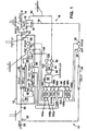
- an amplifier arrangement 10 has a predistortion circuitry 12, a main power amplifier 14, and a control circuitry 16.
- Amplifier 14 is typically a high power class AB amplifier whose output over a line 18 can be either used directly, or can be the input to a feed forward distortion cancellation circuitry such as that described in my U.S. Application Serial No. 08/639,264, entitled BROADBAND AMPLIFIER WITH QUADRATURE PILOT SIGNAL, filed April 24, 1996, the contents of which are incorporated herein by reference.
- the input to the amplifier arrangement, over a line 20, is split (or sampled) for a number of purposes.
- a line sampling coupler 22 directs part of the input signal to a delay element 24.
- the output of the delay element is directed to a controlled gain circuitry 26 and from there to a controlled phase circuitry 28.
- the output for the phase circuitry 28 is passed to a comparison device 30. (The processing order of delay 24, and circuitries 26, 28 is not important).
- the remaining input signal over line 36 is sampled by another coupler 38 and the output of coupler 38 is received by a signal splitter 40 which divides the signal equally for output over lines 42 and 44.
- the remaining input signal from line 36 is directed to a delay element 46.
- the output of splitter 40 over line 42 is directed to a delay element 48, the output of which is received by comparison circuitry 50.
- the other output of splitter 40 over line 44 is received by a gain controlled amplifier 52, the output of which is directed to an auxiliary amplifier 54.
- the output of amplifier 54 is received by a controlled gain circuitry 60.
- the output of controlled gain circuitry 60 is delivered to a controlled phase circuitry 62 the output of which is compared with the signal from delay element 48 in comparison circuitry 50.
- the difference between the two signals, representing distortion components introduced primarily by amplifier 54, is passed through a linear amplifier 64 to a controlled gain circuit 66.
- the output of the control gain circuit 66 is received by a controlled phase circuit 68.
- the output of the controlled phase circuit 68 is delivered to a coupler 70 which combines the output of the phase circuit 68 with the output of the delay element 46, to generate an input, over a line 72, to the main power amplifier 14.
- the distortion error signal over line 80 is amplified using amplifiers 82 and 84, connected in series with each other, and the output of amplifier 84 is detected, here using a Schottky diode 86 to measure the energy in the signal, for input to a digital controller 90.
- the digital controller 90 outputs, in this illustrated embodiment, seven digital signals over lines 92a, 92b, 94a, 94b, 96, 98a, and 98b to control digital to analog (D/A) converters 100a, 100b, 102a, 102b, 104, 106a, and 106b, respectively.
- the analog outputs of the digital to analog converters are directed to control the various gain and phase elements of the predistortor circuitry 12 and the feedback control circuitry gain and phase 26 and 28.
- the output of the comparison circuit 50 amplified by amplifier 64 to give it a proper signal value for eventual coupling into the output from the delay element 46, is sampled by a coupler 118.
- the output of the coupler like the output of comparison circuitry 30, is passed through a pair of amplifiers 120, 122, and is detected at the output of amplifier 122, in the illustrated embodiment of the invention, using a Schottky diode 124, which provides a measure of the energy in the signal output of amplifier 122. That energy value is received by the controller 90 which uses that value to adjust and control the value of the gain at circuits 52 and 60, and the phase correction at circuit 64.
- the circuit arrangement 10 thus has three loops in operation.
- One loop the first distortion loop includes delay 48, amplifier 52, auxiliary amplifier 54, gain and phase correction circuits 60 and 62, and comparison circuitry 50.
- the second distortion loop includes those previous elements, and further, linear amplifier 64, and gain and phase correction circuits 66 and 68, along with delay 46.
- the system error loop includes those previously identified elements plus the main amplifier 14, delay 24, gain and phase correction elements 26 and 28, and comparison circuitry 30.
- the loops are controlled by the error correction circuitry including the processor 90, the A-to-D's 100a, 100b, 102a, 102b, 104, 106a, and 106b, the amplifiers 82, 84, 120, 122, and the detection elements, here the Schottky diodes, 86 and 124.
- the error correction circuitry including the processor 90, the A-to-D's 100a, 100b, 102a, 102b, 104, 106a, and 106b, the amplifiers 82, 84, 120, 122, and the detection elements, here the Schottky diodes, 86 and 124.
- the circuit arrangement operates as follows.
- a sample of the input over line 20 is obtained by coupler 38 and is directed through the voltage variable splitter/attenuator 40 to the linear amplifier 52.
- the purpose of the linear amplifier is to increase the signal level to drive the auxiliary amplifier 54 which has been designed to produce substantially, to the extent possible, the same magnitude and type of distortion as the main amplifier 14.
- the output of the distortion auxiliary amplifier is adjusted by gain and phase correction circuits 60 and 62 and then subtracted from the delayed version of the input signal, from delay 48, to cancel the main input signal in the output of the auxiliary amplifier 54 leaving the distortion, at the output of comparator 50.
- These distortion products are then again amplified, and phase and amplitude corrected, passing through amplifier 64 and then gain and phase correction circuitry 66 and 68.
- the output of phase correction circuitry 68 is then injected 180° out of phase with the original signal.
- the distortion products of a similar nonlinear device (amplifier 54) injected 180° degrees out of phase with the desired signal from delay 46, improves the apparent linearity of the following nonlinear power amplifier 14 operating, for example, as a class AB amplifier.
- the improvement occurs typically in the third order intermodulation products, and is less for the high order products.
- the output of the main amplifier is also sampled by coupler 76.
- the comparison circuit 30 compares the sampled output of the main amplifier with the original input signal processed as follows.
- a sample of the original input signal on line 20 is obtained from coupler 22 and passes through delay line 24.
- the delay lines 24, 46, and 48 are all selected to maintain the signals in time phase as they are coupled together, taking into account the delays inherent in the amplifier and correction circuities.
- the delayed output of delay element 24 is phase and gain corrected and delivered to the comparison circuitry 30, the output of which is a measure of the distortion products at the main amplifier output after a null has been obtained.
- This nulled signal is then used, in part, to control the various elements of the predistortion circuitry 12 and the nulling feed forward circuits 26, 28, to optimize operation at any given power level, temperature, tone spacing, etc.
- the error signal output from comparison circuitry 30 is amplified and isolated by amplifiers 82 and 84, is detected using the Schottky diode 86, in this illustrated embodiment of the invention, and is provided as an input to the processor 90.
- the processor 90 also receives an input from the predistortion circuitry, where the output of the linear amplifier 64, which contains the distortion output from the first distortion loop, is passed through and isolated by amplifiers 120, 122, and detected by Schottky diode 124.
- the Schottky diodes measure the energy contained in the signal applied to them and that energy signal is provided to the controller 90 (through analog to digital converters (not shown)).
- the controller 90 operates on a priority basis, as described below, and based upon the energy inputs applied to it, and its program priority basis, continuously and iteratively outputs digital signal values to the D to A converters.
- the D to A converters upon receiving a new digital signal value, convert their digital inputs to an analog signal output for controlling the various phase and gain elements of the circuitry, that is, the amplifier 52 before the auxiliary amplifier 54, and the gain and phase correction circuits 60, 62, 66, 68, and 26, 28. As these circuits vary in gain and/or phase, the effect is to linearize the input/output relationship from the input signal 20 to the output signal 18 for the entire circuit arrangement. This is performed, as described above, by adding distortion signals (predistorting) to the input of the main amplifier so that the overall response at the output of the main amplifier is linear with respect to the input signal over line 20.
- controller 90 operates substantially in a feedback loop environment. It iteratively adjusts the varying control elements to which it is connected and determines whether the adjustment improves, has no effect, or renders worse, the error products such as the output of the first distortion loop on line 140 or in the error output of the overall device on line 80.
- the object is to minimize the distortion at the output of linear amplifier 14 upon reaching a null at the output of comparator 30.
- the controller operates to give highest priority to the gain and phase control circuits 26, 28, which operate at approximately a millisecond cycle time as opposed to a lower priority in controlling the operation of gain and phase correction circuities 60 and 62 which are updated approximately every three to four milliseconds; and a lowest priority to the adjustment of amplifier 52 and gain and phase correction circuities 66 and 68 which are corrected approximately every 50 milliseconds.
- the control processor can be for example a model MC68HC11E9 processor manufactured by Motorola.
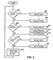
- controller 90 loops between the various correction circuities in order to continuously maintain and update the correction output values.
- the system first checks whether to adjust gain and phase correction circuits 26, 28. This decision can be based, for example, upon an internal clock measurement so that these elements can be updated every millisecond. This is tested at step 200. If the elements are to be adjusted, then the gain can be adjusted at step 202 and the phase can be adjusted at step 204, after which control returns to the main loop. Thereafter, the system determines whether to adjust the control voltages to gain amplifier 52, gain correction circuit 66, and gain correction circuit 68.
- step 206 If, the decision at step 206 is "yes", the control signals to each of the three elements are adjusted in sequence at steps 208, 210, and 214. Control then again returns to the main loop. Finally, the system checks at 218 whether to adjust the signals controlling gain and phase correction circuits 60 and 62. If the gain and phase are to be adjusted, the system then adjusts, as necessary, those elements at 220 and 222 and control returns to the main loop. The next step reads new detector values at the inputs from detection elements 86 and 124. This is indicated at step 224.
- gain and phase correction circuitries 26 and 28 are adjusted based solely upon the error signal value from detector 86.
- gain element 52 and gain and phase correction circuitries 66 and 68 are also determined based solely on the signal level of detector 86.
- the gain and phase correction circuits 60 and 62 are adjusted based solely upon the detector output measurements of detector 124.
Landscapes
- Engineering & Computer Science (AREA)
- Power Engineering (AREA)
- Physics & Mathematics (AREA)
- Nonlinear Science (AREA)
- Amplifiers (AREA)
Claims (18)
- Système d'amplificateur pour amplifier un signal d'entrée avec lequel est combinée une entrée d'annulation de distorsion, ledit système d'amplificateur comprenant :un amplificateur principal (14),une boucle d'erreur comprenantun comparateur (30) qui différencie une dérivée (78) à retard dudit signal d'entrée appliqué audit système d'amplificateur d'avec un signal représentant la sortie (18) dudit amplificateur principal pour créer un signal d'erreur (80) ;une première boucle de réaction commandée par la distorsion, comprenantun détecteur (86) pour recevoir ledit signal d'erreur et générer une sortie de signal d'erreur détecté ; etun circuit (12) générateur de signal de distorsion pour générer un signal de distorsion, comportantun amplificateur auxiliaire (54) pour recevoir un signal dérivé dudit signal d'entrée et générer une sortie de signal auxiliaire,des circuits (60, 66) de correction de signal pour recevoir le signal auxiliaire de sortie afin de régler le gain et la phase dudit signal auxiliaire de sortie, etun premier combinateur (50) pour combiner une version retardée dudit signal d'entrée avec une sortie desdits circuits de correction de signal afin de générer un signal de composante de distorsion,un second combinateur (70) pour combiner ledit signal de composante de distorsion avec une réplique à retard dudit signal d'entrée pour les appliquer auxdits amplificateurs principaux, etladite boucle de réaction commandée comportant en outre un circuit de compensation (90) connecté à la sortie de signal de commande d'erreur détectée du détecteur pour générer des signaux de commande de prédistorsion appliqués aux circuits de correction, lesdites informations d'extraction de détecteur obtenues à partir du signal d'erreur et desdits signaux de commande limitant ladite sortie de signal d'erreur détecté
- Système d'amplificateur selon la revendication 1, dans lequel ledit amplificateur principal est un amplificateur de fréquence radioélectrique à large bande fonctionnant en mode de classe AB.
- Système d'amplificateur selon la revendication 1, comprenant en outre des circuits de correction de phase et de gain dans ladite boucle d'erreur pour régler ledit signal d'entrée.
- Système d'amplificateur selon la revendication 1, dans lequel, en outre :ladite boucle d'erreur comporteun circuit à retard de boucle d'erreur connecté pour recevoir un signal dérivé dudit signal d'entrée à amplifier, etdes circuits de correction de phase et de gain de boucle d'erreur, montés en série avec ledit circuit à retard de boucle d'erreur,ledit circuit à retard de boucle d'erreur et lesdits circuits de correction de phase et d'amplitude de boucle d'erreur générant conjointement ladite dérivée à retard dudit signal d'entrée.
- Système d'amplificateur selon la revendication 4, dans lequel, en outreledit détecteur comporte un circuit de mesure d'énergie pour mesurer l'énergie dans ledit signal d'erreur, etledit circuit de compensation comporte un processeur de commande, réagissant au circuit de mesure d'énergie, pour régler de manière itérative l'amplitude et la phase des circuits de correction de signal.
- Système d'amplificateur selon la revendication 5, dans lequel ledit circuit générateur de signal de distorsion comporte un premier circuit de correction de gain et un premier circuit de commande de phase, et ledit processeur de commande comporte :un moyen de commande pour régler de manière cyclique ledit circuit de commande de correction de phase, puis ledit circuit de commande de correction de gain, suivant un modèle de répétition continue.
- Système d'amplificateur selon la revendication 4, dans lequel ledit circuit de mesure d'énergie est un circuit à diode Schottky.
- Système d'amplificateur selon la revendication 6, dans lequel lesdits circuits de correction de phase et de gain réalisent une correction de phase et de gain à ladite sortie de l'amplificateur auxiliaire.
- Système d'amplificateur selon la revendication 8, comprenant en outreun moyen à retard pour recevoir un signal dérivé dudit signal d'entrée et pour produire ladite version à retard de son entrée comme signal à retard de sortie, appliqué audit premier combinateur,ledit premier combinateur délivrant une différence entre la version à retard délivrée par le moyen à retard et la sortie dérivée de l'amplificateur auxiliaire,un deuxième circuit de correction de phase,un deuxième circuit de correction de gain, etlesdits seconds circuits de correction de phase et de gain réalisant une correction de phase et de gain sur la sortie dudit premier comparateur avant la combinaison avec ladite réplique à retard.
- Système d'amplificateur selon la revendication 9, comprenant en outreun second circuit de détection pour recevoir une sortie dérivée dudit premier combinateur pour générer un signal d'erreur de distorsion, ledit processeur de commande réagissant audit signal d'erreur de distorsion pour régler de manière itérative les premiers circuits de correction de phase et de gain,ledit processeur de commande réagissant audit signal d'erreur pour régler de manière itérative lesdits seconds circuits de correction de phase et de gain et lesdits circuits de correction de phase et de gain de la boucle d'erreur, etledit processeur de commande établissant une priorité sur une fréquence à laquelle sont réglés de manière itérative les circuits.
- Système d'amplificateur selon la revendication 10, comprenant en outreun amplificateur linéaire réagissant à la sortie du premier combinateur pour amplifier ledit signal de sortie du premier combinateur et délivrer la sortie amplifiée auxdits seconds circuits de correction de gain et de phase.
- Système d'amplificateur selon la revendication 10, comprenant en outre, dans ladite boucle de distorsion,un circuit de commande de gain à l'entrée dudit amplificateur auxiliaire, et ledit processeur de commande commande de manière interactive le gain desdits circuits de commande de gain en réponse audits signaux d'entrée du processeur.
- Système de d'amplificateur selon la revendication 5, dans lequel, en outre, ledit processeur de commande réagit pour commander de manière itérative, avec une faible priorité, lesdits circuits de commande de gain et de phase de ladite boucle de commande d'erreur, en réponse auxdits circuits de détection de signal d'erreur.
- Procédé de correction de distorsion dans un signal amplifié délivré par un amplificateur principal d'un système d'amplificateur, ledit amplificateur principal faisant partie du système d'amplificateur et le système ayant une entrée et une sortie, ledit procédé combinant des signaux de prédistorsion avec l'entrée dudit système d'amplificateur pour les appliquer audit amplificateur principal, comprenant les étapes consistant à :générer lesdits signaux de prédistorsion dans un circuit de prédistorsion comportant un amplificateur auxiliaire, à partir d'une entrée dudit système d'amplificateur,générer un signal d'erreur à partir d'un signal dérivé du signal d'entrée et la sortie de l'amplificateur principal représentant l'énergie d'erreur de distorsion,corriger de manière itérative et successive, à l'aide d'un processeur à commande numérique réagissant au moins à des signaux dérivés dudit signal d'erreur, des réglages de phase et de gain dans ledit circuit de prédistorsion.
- Procédé selon la revendication 14, dans lequel ladite étape de correction itérative est une réaction à des signaux d'erreur de distorsion générés dans ledit circuit de prédistorsion.
- Procédé selon la revendication 15, dans lequel ladite étape de génération de signal d'erreur comprend les étapes consistant àcomparer un signal dérivé de la sortie de l'amplificateur principal et un signal dérivé du signal d'entrée du système d'amplificateur pour générer un signal de différence, etmesurer une énergie contenue dans un signal dérivé dudit signal de différence.
- Procédé selon la revendication 14, comprenant en outre les étapes consistant àfaire passer un signal dans un amplificateur auxiliaire ayant des caractéristiques de distorsion semblables à celles dudit amplificateur principal,régler de manière itérative la phase et le gain agissant sur une sortie dudit amplificateur auxiliaire à l'aide dudit processeur à commande numérique, etrégler de manière itérative une phase et un gain d'un signal de réplique d'entrée à retard à l'aide dudit processeur à commande numérique, ledit signal de réplique réglé servant à générer ledit signal d'erreur.
- Procédé selon la revendication 17, comprenant en outre l'étape consistant à réaliser à des cadences périodiques différentes lesdites étapes de réglage et de correction itératifs.
Applications Claiming Priority (3)
| Application Number | Priority Date | Filing Date | Title |
|---|---|---|---|
| US09/057,332 US6046635A (en) | 1998-04-08 | 1998-04-08 | Dynamic predistortion compensation for a power amplifier |
| US57332 | 1998-04-08 | ||
| PCT/US1999/007648 WO1999052205A1 (fr) | 1998-04-08 | 1999-04-07 | Correction de predistorsion dynamique pour un amplificateur de puissance |
Publications (3)
| Publication Number | Publication Date |
|---|---|
| EP0988694A1 EP0988694A1 (fr) | 2000-03-29 |
| EP0988694A4 EP0988694A4 (fr) | 2002-06-12 |
| EP0988694B1 true EP0988694B1 (fr) | 2005-06-22 |
Family
ID=22009939
Family Applications (1)
| Application Number | Title | Priority Date | Filing Date |
|---|---|---|---|
| EP99916474A Expired - Lifetime EP0988694B1 (fr) | 1998-04-08 | 1999-04-07 | Correction de predistorsion dynamique pour un amplificateur de puissance |
Country Status (7)
| Country | Link |
|---|---|
| US (1) | US6046635A (fr) |
| EP (1) | EP0988694B1 (fr) |
| KR (1) | KR20010013534A (fr) |
| BR (1) | BR9906348A (fr) |
| CA (1) | CA2293337C (fr) |
| DE (1) | DE69925887T2 (fr) |
| WO (1) | WO1999052205A1 (fr) |
Cited By (1)
| Publication number | Priority date | Publication date | Assignee | Title |
|---|---|---|---|---|
| US9094067B2 (en) | 2012-09-12 | 2015-07-28 | Mediatek Singapore Pte. Ltd. | Method and apparatus for calibrating an envelope tracking system |
Families Citing this family (18)
| Publication number | Priority date | Publication date | Assignee | Title |
|---|---|---|---|---|
| JP4634557B2 (ja) * | 1999-11-30 | 2011-02-16 | 富士通株式会社 | 信号キャンセル方法及びその装置 |
| JP3877937B2 (ja) * | 2000-05-18 | 2007-02-07 | 株式会社エヌ・ティ・ティ・ドコモ | フィードフォワード増幅器 |
| US6420929B1 (en) | 2001-08-23 | 2002-07-16 | Thomas Ha | N way cancellation coupler for power amplifier |
| US6700442B2 (en) * | 2001-11-20 | 2004-03-02 | Thomas Quang Ha | N way phase cancellation power amplifier |
| US6812786B2 (en) | 2002-04-11 | 2004-11-02 | Andrew Corporation | Zero-bias bypass switching circuit using mismatched 90 degrees hybrid |
| US6700439B2 (en) | 2002-04-11 | 2004-03-02 | Andrew Corporation | Zero-bias bypass switch |
| US6930547B2 (en) * | 2002-08-09 | 2005-08-16 | Andrew Corporation | Linearizing LINC amplifiers using pre-distortion |
| US7038540B2 (en) | 2003-02-14 | 2006-05-02 | Powerwave Technologies, Inc. | Enhanced efficiency feed forward power amplifier utilizing reduced cancellation bandwidth and small error amplifier |
| US6812792B2 (en) * | 2003-01-02 | 2004-11-02 | Harris Corporation | Precorrection of a nonlinear amplifier |
| US7403573B2 (en) * | 2003-01-15 | 2008-07-22 | Andrew Corporation | Uncorrelated adaptive predistorter |
| US7729668B2 (en) | 2003-04-03 | 2010-06-01 | Andrew Llc | Independence between paths that predistort for memory and memory-less distortion in power amplifiers |
| US6972622B2 (en) * | 2003-05-12 | 2005-12-06 | Andrew Corporation | Optimization of error loops in distributed power amplifiers |
| US7259630B2 (en) * | 2003-07-23 | 2007-08-21 | Andrew Corporation | Elimination of peak clipping and improved efficiency for RF power amplifiers with a predistorter |
| US6963242B2 (en) * | 2003-07-31 | 2005-11-08 | Andrew Corporation | Predistorter for phase modulated signals with low peak to average ratios |
| US7023273B2 (en) * | 2003-10-06 | 2006-04-04 | Andrew Corporation | Architecture and implementation methods of digital predistortion circuitry |
| CN101656512B (zh) * | 2008-08-18 | 2012-06-27 | 富士通株式会社 | 功率放大器非线性程度度量装置、方法和预失真补偿装置 |
| CN111121608B (zh) * | 2019-12-25 | 2021-03-26 | 枣阳市米朗科技有限公司 | 一种利用肖特基二极管对电涡流传感器输出线性进行多级修正的电路 |
| CN111010095B (zh) * | 2019-12-27 | 2021-11-09 | 湖南华诺星空电子技术有限公司 | 一种无线通信系统的宽带功放线性化处理方法及系统 |
Family Cites Families (31)
| Publication number | Priority date | Publication date | Assignee | Title |
|---|---|---|---|---|
| US3471798A (en) * | 1967-12-26 | 1969-10-07 | Bell Telephone Labor Inc | Feed-forward amplifier |
| US3755754A (en) * | 1972-02-04 | 1973-08-28 | Varian Associates | Predistortion compensation for a microwave amplifier |
| US3725806A (en) * | 1972-06-09 | 1973-04-03 | Bell Telephone Labor Inc | Distortion reduction in a repeatered transmission system |
| US3825843A (en) * | 1973-06-08 | 1974-07-23 | Bell Telephone Labor Inc | Selective distortion compensation circuit |
| FR2418981A1 (fr) * | 1978-03-03 | 1979-09-28 | Lignes Telegraph Telephon | Circuit d'amplification pour telecommunication en hyperfrequence |
| US4291277A (en) * | 1979-05-16 | 1981-09-22 | Harris Corporation | Adaptive predistortion technique for linearizing a power amplifier for digital data systems |
| US4453133A (en) * | 1982-04-05 | 1984-06-05 | Bell Telephone Laboratories, Incorporated | Active predistorter for linearity compensation |
| US4564816A (en) * | 1984-05-09 | 1986-01-14 | Rca Corporation | Predistortion circuit |
| US4554514A (en) * | 1984-12-21 | 1985-11-19 | Rca Corporation | Predistortion circuit with feedback |
| US4588958A (en) * | 1985-03-29 | 1986-05-13 | Rca Corporation | Adjustable reflective predistortion circuit |
| US4943782A (en) * | 1988-03-21 | 1990-07-24 | Hughes Aircraft Company | Four-pass phase conjugate optical amplifier system and method |
| US4879519A (en) * | 1988-10-31 | 1989-11-07 | American Telephone And Telegraph Company, At&T Bell Labs | Predistortion compensated linear amplifier |
| US4882547A (en) * | 1988-11-15 | 1989-11-21 | General Electric Company | Linearizer control system |
| US5252930A (en) * | 1989-09-07 | 1993-10-12 | Ortel Corporation | Predistorter for linearization of electronic and optical signals |
| US5132639A (en) * | 1989-09-07 | 1992-07-21 | Ortel Corporation | Predistorter for linearization of electronic and optical signals |
| GB2238196A (en) * | 1989-11-16 | 1991-05-22 | Motorola Inc | Feed forward amplifier with pre-distortion |
| US5049832A (en) * | 1990-04-20 | 1991-09-17 | Simon Fraser University | Amplifier linearization by adaptive predistortion |
| US5334946A (en) * | 1990-04-25 | 1994-08-02 | British Technology Group Limited | Apparatus and method for reducing distortion in amplification |
| CA2046413C (fr) * | 1990-07-11 | 1994-01-04 | Shoichi Narahashi | Amplificateur a correction aval |
| EP0465709A1 (fr) * | 1990-07-12 | 1992-01-15 | Thomcast Ag | Procédé de compensation des produits non linéaires d'un amplificateur |
| US5170495A (en) * | 1990-10-31 | 1992-12-08 | Northern Telecom Limited | Controlling clipping in a microwave power amplifier |
| US5193224A (en) * | 1991-04-24 | 1993-03-09 | Northern Telecom Limited | Adaptive phase control for a power amplifier predistorter |
| US5237288A (en) * | 1992-06-05 | 1993-08-17 | Sea, Inc. | RF power amplifier linearization |
| JPH07147547A (ja) * | 1993-11-24 | 1995-06-06 | Nec Corp | フィードフォワード型歪補償回路 |
| IT1265271B1 (it) * | 1993-12-14 | 1996-10-31 | Alcatel Italia | Sistema di predistorsione in banda base per la linearizzazione adattativa di amplificatori di potenza |
| US5485120A (en) * | 1994-07-28 | 1996-01-16 | Aval Communications Inc. | Feed-forward power amplifier system with adaptive control and control method |
| US5444418A (en) * | 1994-07-29 | 1995-08-22 | Motorola, Inc. | Method and apparatus for feedforward power amplifying |
| US5523716A (en) * | 1994-10-13 | 1996-06-04 | Hughes Aircraft Company | Microwave predistortion linearizer |
| US5621354A (en) * | 1995-10-17 | 1997-04-15 | Motorola, Inc. | Apparatus and method for performing error corrected amplification in a radio frequency system |
| US5789976A (en) * | 1996-06-17 | 1998-08-04 | Corporation De L'ecole Polytechnique | Digital adaptive control of feedforward amplifier using frequency domain cancellation |
| US5867064A (en) * | 1996-08-19 | 1999-02-02 | Motorola, Inc. | Method and apparatus for improving intermodulation in a feed-forward amplifier |
-
1998
- 1998-04-08 US US09/057,332 patent/US6046635A/en not_active Expired - Lifetime
-
1999
- 1999-04-07 BR BR9906348-4A patent/BR9906348A/pt not_active IP Right Cessation
- 1999-04-07 DE DE69925887T patent/DE69925887T2/de not_active Expired - Lifetime
- 1999-04-07 EP EP99916474A patent/EP0988694B1/fr not_active Expired - Lifetime
- 1999-04-07 CA CA002293337A patent/CA2293337C/fr not_active Expired - Fee Related
- 1999-04-07 WO PCT/US1999/007648 patent/WO1999052205A1/fr not_active Ceased
- 1999-04-07 KR KR1019997011541A patent/KR20010013534A/ko not_active Ceased
Cited By (2)
| Publication number | Priority date | Publication date | Assignee | Title |
|---|---|---|---|---|
| US9094067B2 (en) | 2012-09-12 | 2015-07-28 | Mediatek Singapore Pte. Ltd. | Method and apparatus for calibrating an envelope tracking system |
| US9118366B2 (en) | 2012-09-12 | 2015-08-25 | Mediatek Singapore Pte. Ltd. | Method and apparatus for calibrating an envelope tracking system |
Also Published As
| Publication number | Publication date |
|---|---|
| KR20010013534A (ko) | 2001-02-26 |
| BR9906348A (pt) | 2000-09-19 |
| WO1999052205A1 (fr) | 1999-10-14 |
| US6046635A (en) | 2000-04-04 |
| CA2293337A1 (fr) | 1999-10-14 |
| EP0988694A1 (fr) | 2000-03-29 |
| DE69925887T2 (de) | 2006-04-20 |
| DE69925887D1 (de) | 2005-07-28 |
| EP0988694A4 (fr) | 2002-06-12 |
| CA2293337C (fr) | 2004-10-26 |
Similar Documents
| Publication | Publication Date | Title |
|---|---|---|
| CA2388512C (fr) | Compensation amelioree de predistorsion pour amplificateur de puissance | |
| EP0988694B1 (fr) | Correction de predistorsion dynamique pour un amplificateur de puissance | |
| EP0995261B1 (fr) | Polarisation adaptative dans un amplificateur de puissance | |
| US10651809B2 (en) | Control system for a power amplifier | |
| JP2000512111A (ja) | 適応型予歪付与回路を有するrfアンプ | |
| US6169450B1 (en) | Feed forward compensation using phase and time modulation | |
| US6127889A (en) | Nested feed forward distortion reduction system | |
| US6531918B1 (en) | Low cost, pilotless, feed forward compensation for a power amplifier | |
| US6166600A (en) | Automatic gain and phase controlled feedforward amplifier without pilot signal | |
| US6326840B1 (en) | Feed-forward distortion compensation amplifier and method of amplifying signal with feed-forward distortion compensation | |
| US6191652B1 (en) | Amplifier distortion correction using cross-modulation | |
| KR100456252B1 (ko) | 피드포워드 증폭기 | |
| KR20010010892A (ko) | 통신시스템에서의 개선된 왜곡 신호 보상 장치 | |
| KR100311518B1 (ko) | 입력 신호의 위상 제어를 이용한 왜곡된 신호의 보상 방법 및장치. |
Legal Events
| Date | Code | Title | Description |
|---|---|---|---|
| PUAI | Public reference made under article 153(3) epc to a published international application that has entered the european phase |
Free format text: ORIGINAL CODE: 0009012 |
|
| 17P | Request for examination filed |
Effective date: 20000106 |
|
| AK | Designated contracting states |
Kind code of ref document: A1 Designated state(s): DE FI FR GB SE |
|
| A4 | Supplementary search report drawn up and despatched |
Effective date: 20020503 |
|
| AK | Designated contracting states |
Kind code of ref document: A4 Designated state(s): DE FI FR GB SE |
|
| RIC1 | Information provided on ipc code assigned before grant |
Free format text: 7H 03F 1/26 A, 7H 03F 1/32 B |
|
| GRAP | Despatch of communication of intention to grant a patent |
Free format text: ORIGINAL CODE: EPIDOSNIGR1 |
|
| GRAS | Grant fee paid |
Free format text: ORIGINAL CODE: EPIDOSNIGR3 |
|
| GRAA | (expected) grant |
Free format text: ORIGINAL CODE: 0009210 |
|
| AK | Designated contracting states |
Kind code of ref document: B1 Designated state(s): DE FI FR GB SE |
|
| REG | Reference to a national code |
Ref country code: GB Ref legal event code: FG4D |
|
| REF | Corresponds to: |
Ref document number: 69925887 Country of ref document: DE Date of ref document: 20050728 Kind code of ref document: P |
|
| REG | Reference to a national code |
Ref country code: SE Ref legal event code: TRGR |
|
| PLBE | No opposition filed within time limit |
Free format text: ORIGINAL CODE: 0009261 |
|
| STAA | Information on the status of an ep patent application or granted ep patent |
Free format text: STATUS: NO OPPOSITION FILED WITHIN TIME LIMIT |
|
| 26N | No opposition filed |
Effective date: 20060323 |
|
| EN | Fr: translation not filed | ||
| PG25 | Lapsed in a contracting state [announced via postgrant information from national office to epo] |
Ref country code: FR Free format text: LAPSE BECAUSE OF FAILURE TO SUBMIT A TRANSLATION OF THE DESCRIPTION OR TO PAY THE FEE WITHIN THE PRESCRIBED TIME-LIMIT Effective date: 20060818 |
|
| PG25 | Lapsed in a contracting state [announced via postgrant information from national office to epo] |
Ref country code: FR Free format text: LAPSE BECAUSE OF FAILURE TO SUBMIT A TRANSLATION OF THE DESCRIPTION OR TO PAY THE FEE WITHIN THE PRESCRIBED TIME-LIMIT Effective date: 20050622 |
|
| REG | Reference to a national code |
Ref country code: DE Ref legal event code: R082 Ref document number: 69925887 Country of ref document: DE Representative=s name: FUCHS PATENTANWAELTE PARTNERSCHAFT MBB, DE |
|
| REG | Reference to a national code |
Ref country code: DE Ref legal event code: R082 Ref document number: 69925887 Country of ref document: DE Representative=s name: FUCHS PATENTANWAELTE PARTNERSCHAFT MBB, DE Effective date: 20150220 Ref country code: DE Ref legal event code: R081 Ref document number: 69925887 Country of ref document: DE Owner name: INTEL CORPORATION (A DELAWARE CORPORATION), SA, US Free format text: FORMER OWNER: POWERWAVE TECHNOLOGIES, INC., IRVINE, CALIF., US Effective date: 20150220 |
|
| REG | Reference to a national code |
Ref country code: GB Ref legal event code: 732E Free format text: REGISTERED BETWEEN 20150501 AND 20150506 |
|
| REG | Reference to a national code |
Ref country code: GB Ref legal event code: 732E Free format text: REGISTERED BETWEEN 20150507 AND 20150513 |
|
| PGFP | Annual fee paid to national office [announced via postgrant information from national office to epo] |
Ref country code: GB Payment date: 20170405 Year of fee payment: 19 Ref country code: DE Payment date: 20170404 Year of fee payment: 19 |
|
| PGFP | Annual fee paid to national office [announced via postgrant information from national office to epo] |
Ref country code: SE Payment date: 20170411 Year of fee payment: 19 Ref country code: FI Payment date: 20170410 Year of fee payment: 19 |
|
| REG | Reference to a national code |
Ref country code: DE Ref legal event code: R119 Ref document number: 69925887 Country of ref document: DE |
|
| REG | Reference to a national code |
Ref country code: SE Ref legal event code: EUG |
|
| GBPC | Gb: european patent ceased through non-payment of renewal fee |
Effective date: 20180407 |
|
| PG25 | Lapsed in a contracting state [announced via postgrant information from national office to epo] |
Ref country code: SE Free format text: LAPSE BECAUSE OF NON-PAYMENT OF DUE FEES Effective date: 20180408 Ref country code: FI Free format text: LAPSE BECAUSE OF NON-PAYMENT OF DUE FEES Effective date: 20180407 Ref country code: DE Free format text: LAPSE BECAUSE OF NON-PAYMENT OF DUE FEES Effective date: 20181101 |
|
| PG25 | Lapsed in a contracting state [announced via postgrant information from national office to epo] |
Ref country code: GB Free format text: LAPSE BECAUSE OF NON-PAYMENT OF DUE FEES Effective date: 20180407 |