EP0988527B1 - Detecteur electrochimioluminescent - Google Patents
Detecteur electrochimioluminescent Download PDFInfo
- Publication number
- EP0988527B1 EP0988527B1 EP98922566A EP98922566A EP0988527B1 EP 0988527 B1 EP0988527 B1 EP 0988527B1 EP 98922566 A EP98922566 A EP 98922566A EP 98922566 A EP98922566 A EP 98922566A EP 0988527 B1 EP0988527 B1 EP 0988527B1
- Authority
- EP
- European Patent Office
- Prior art keywords
- detector according
- cells
- substrate
- electrodes
- photodiode
- Prior art date
- Legal status (The legal status is an assumption and is not a legal conclusion. Google has not performed a legal analysis and makes no representation as to the accuracy of the status listed.)
- Expired - Lifetime
Links
Images

Classifications
-
- G—PHYSICS
- G01—MEASURING; TESTING
- G01N—INVESTIGATING OR ANALYSING MATERIALS BY DETERMINING THEIR CHEMICAL OR PHYSICAL PROPERTIES
- G01N21/00—Investigating or analysing materials by the use of optical means, i.e. using sub-millimetre waves, infrared, visible or ultraviolet light
- G01N21/62—Systems in which the material investigated is excited whereby it emits light or causes a change in wavelength of the incident light
- G01N21/66—Systems in which the material investigated is excited whereby it emits light or causes a change in wavelength of the incident light electrically excited, e.g. electroluminescence
- G01N21/69—Systems in which the material investigated is excited whereby it emits light or causes a change in wavelength of the incident light electrically excited, e.g. electroluminescence specially adapted for fluids, e.g. molten metal
-
- G—PHYSICS
- G01—MEASURING; TESTING
- G01N—INVESTIGATING OR ANALYSING MATERIALS BY DETERMINING THEIR CHEMICAL OR PHYSICAL PROPERTIES
- G01N21/00—Investigating or analysing materials by the use of optical means, i.e. using sub-millimetre waves, infrared, visible or ultraviolet light
- G01N21/75—Systems in which material is subjected to a chemical reaction, the progress or the result of the reaction being investigated
- G01N21/76—Chemiluminescence; Bioluminescence
Definitions
- the present invention relates to electrochemiluminescent systems. More particularly, it relates to a detector and a method for dosing of substances by generation and detection of electrogenerated chemiluminescence (ECL) or electrochemiluminescence.
- ECL electrogenerated chemiluminescence
- Chemiluminescence is used for the determination of substances biochemical and biological. It allows in particular the measurement of traces of microorganisms, hormones, viruses, antibodies, amines or proteins.
- Chemiluminescence assay consists of marking the substance sought using a chemiluminescent agent whose detection and dosing are carried out by measuring the light emitted when after being placed in an excited state, it returns to its initial state.
- the excited state allowing the emission of light is the product of a reaction chemical between two particular substances.
- the present invention relates more particularly to systems using a reaction electrochemical, called electrochemiluminescent systems, in which at least one of the reagents is produced electrochemically from a substance initially present in the solution.
- Known electrochemiluminescent systems generally include a cell for the generation and detection of chemiluminescence electrogenerated, which comprises at least one working electrode, means power supply of the electrode, a photodiode for detect the light generated and means for measuring the signal delivered by the photodiode.
- the object of the present invention is to take an additional step in the production of very small electrochemiluminescent detectors dimensions, simple and practical to use, low cost and allowing broad fields of applications.
- such a detector is mainly characterized by what the photodiode is achieved by integration into the substrate of the working electrode.
- the cell has two interdigitated working electrodes which are used one as an anode and the other as a cathode.
- the cathode is made of carbon and the anode of a material chosen from platinum, gold, carbon and transparent metal oxides.
- the distance between the cathode and the anode is less than 10 microns.
- the cell comprises a layer of passivation in which the electrodes are integrated, while leaving a part of their upper face in contact with the outside, as well as a layer intermediate made of a dielectric material, disposed between the electrode and the substrate.
- the detector according to the invention comprises two cells of identical measurements, as described above, including the electrodes respective are carried out on the same substrate and whose photodiodes respective are made by integration into said substrate.
- the electrode only one of the cells is connected to the supply means, and the measuring means include means for determining the difference between the signals delivered by the photodiodes of the two cells.
- the passivation layer and the intermediate layer are common to both cells.
- the object of the invention is also achieved by a method according to which the substance to be dosed is in aqueous solution.
- the cathode is made of carbon
- the anode is made of a chosen material among platinum, gold, carbon and other materials known to man of art, especially transparent metal oxides, the distance between cathode and anode being less than 10 microns.
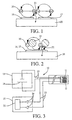
- the electrochemiluminescent detector 10 essentially comprises two cells of identical measures 11 and 12, the same constituents of which are designated by the same reference numbers.
- Each cell has two working electrodes, an anode 16 and a cathode 17, which are separated by a distance of less than 10 microns, from means 13 for electrical supply to the electrodes of the cell 11 only a photoelectric detector 14 for detecting light generated by electrochemiluminescence and measuring means 15 of the detector output 14.
- Cell 11 is the so-called active cell, while cell 12 is the so-called cell for the measurement of background noise, which is why it is not supplied with electrical energy.
- the anode 16 and the cathode 17 are interdigitated. They are separated by a distance of less than 10 microns. Of advantageously, although it is not essential, these two electrodes are protected by a passivation layer 18 leaving a part of their upper face in contact with the outside. Everything is deposited on an intermediate layer 19, itself produced on a substrate of silicon 20, n-type.
- the electrodes 16 and 17 are interdigitated, but other layouts and geometries are possible as long as the distance separating them is less than 10 microns.
- the passivation layer 18, the intermediate layer 19 and the substrate 20 are common to both cells.
- the photoelectric detector 14 consists of a photodiode formed of a n-type diffused area in the p-type substrate 20, under the electrodes interdigitated 16 and 17.
- the photodiode 14 is produced by integration in the substrate 20 on which the interdigitated working electrodes 16 are deposited and 17.
- the intermediate layer 19 is formed of a dielectric material and provides galvanic isolation between electrodes 16 and 17 and photodiode 14. This layer also serves to protect the cells against chemical attack by the surrounding environment. This minimizes the risks cell damage.
- Another function of the intermediate layer 19 is to reduce the reflection light at the interface with substrate 20. This is done by adjusting the thickness and the refractive index of the layer as a function of the wavelength of the light emitted, which depends on the product used as a marker.
- the marker is Ruthenium (II) tris (2,2 '- bipyridyl).
- Other products, such as luminol, can also be used.
- the intermediate layer 19 is made of silicon nitride Si 3 N 4 and has a thickness of approximately 0.4 micron, so as to minimize the reflections at 610 nm corresponding to the maximum emission wavelength of ruthenium when that -this is used as a marker.
- This layer is advantageously deposited by a deposition process known under the name of "Plasma enhanced chemical vapor deposition" and under the abbreviation PECVD.
- the electrodes 16 and 17 are made of platinum, gold, carbon or transparent metal oxides known to those skilled in the art. In this case, they can be used to measure substances in organic solutions. They can also be used in single electrode detectors of work, that is to say in which the two interdigitated electrodes are electrically connected to each other.
- the cathode 17 can be made in carbon, the anode 16 can equally be formed from platinum, gold, carbon or transparent metal oxides.
- the two electrodes are close enough, i.e. at a distance less than 10 microns, it is possible to carry out a dosage of components in solution exclusively aqueous or also in organic solution.
- the upper passivation layer 18 makes it possible to isolate the cells from the ambient medium, in order to minimize the risks of deterioration due to chemical attacks from this medium.
- This layer 18 can be made of a material such as silicon nitride Si 3 N 4 . Its thickness is approximately 0.4 micron and can also be deposited by the “PECVD” method mentioned above.
- the supply means 13 of the active cell 11 comprise a source electrical energy 21 and conductive tracks 22 produced on a support, such as a printed circuit board, at the end of which are arranged the two cells. These conductive tracks 22 connect the electrodes 16 and 17 from the active cell 11 to the source 21.
- the source delivers a triangular alternating voltage, at the speed of 100 mV / sec, varying from -1.45 V at 1.65 V at the cathode, and a DC voltage of 1.65 V at the anode.
- the measurement means 15 essentially comprise two tracks conductors 23 made on the support of the two cells and connect the two photodiodes 14 to two amplifiers 24. These amplifiers receive the photocurrent generated by photodiodes and deliver an amplified signal to a measuring device 25. This then determines a signal representative of the difference between the signal supplied by the photodetector of the active cell 11 and that provided by the photodetector of the reference cell 12.
- the electrical connections 22 between the electrodes 16 and 17 of the active cell 11 and the power source 21, and the electrical connections 23 between the two photodiodes 14 and the amplifiers 24 are made via connection zones 26 produced at one end cells.
- the two interdigitated working electrodes are used respectively as anode and cathode. More specifically, the protein to be assayed marked with ruthenium (II) tris (2, 2'-bipyridyl), Ru (bpy) 3 2+ , is introduced into an aqueous solution. The two cells 11 and 12 are then placed in the container. In active cell 11, Ru (bpy) 3 2+ reduces at cathode 17 to Ru (bpy) 3 + and oxidizes to Ru (bpy) 3 3+ at anode 16. Following an annihilation reaction between Ru (bpy) 3 + and Ru (bpy) 3 3+ , photons are released and detected by photodiode 14 of active cell 11. This reaction is illustrated in particular in FIG. 1.
- the photocurrent generated by the release of photons is amplified by the amplifier 24 then sent to the measuring device 25.
- a stray photocurrent is generated at the two photodiodes 14. It is due to the light coming from the environment but also to the background noise of the cells themselves. This effect varies depending on temperature, which implies that it is difficult to take it into account by calculation.
- the stray current affecting the measurement of the active cell 11 is determined alone by means of the photodiode 14 of the reference cell 12 which is not powered. Of course, this is valid as long as the two cells are subject to the same conditions and that they were carried out same way.
- the measuring device 25 determines, in the measuring device 25, a difference between the signals from each of the two cells, we get a corresponding value to the current generated only by electrochemiluminescence.
- the measure is independent of stray light and temperature variations. It is therefore possible to perform measurements in ambient light, as well as in conditions under which the temperature varies.
- the two interdigitated electrodes are used as a single working electrode.
- the cells are then the same as the cells with two electrodes, with the only difference that these are simply connected to each other, i.e. inside the cells or outside, for example at the tracks conductive.
- the aqueous solution containing the ruthenium-labeled protein differs from that of the first method in that a co-reagent, such as an amine, is used.
- An amine and ruthenium oxidation reaction is then induced by feeding the anode.
- the chemical reaction between the oxidized amine and the Ru (bpy) 3 3+ generates the excited state of the ruthenium which produces the light detected by the photodiode 14. This reaction is illustrated in particular in FIG. 2.
- the measurement of the current delivered by the photodiode 14 gives a measurement of the number of photons emitted and therefore a measure of the amount of marker, therefore of the substance to be dosed.
- the detector according to the invention which has just been described, thus makes it possible to produce, in a simple way, measurements with cells with one or two electrodes, depending on the method chosen.
- a particularly important advantage of this detector is that it integrates, in the same cell, the electrodes 16 and 17 and the photodiode 14. This makes this device particularly reliable and easy to use.
- the proximity of the anode and the cathode and the use of a carbon cathode allow measurements to be made aqueous solution only, which is not possible with the devices currently known.
- the present invention is not limited to the embodiments described.
- the materials used for the different layers and, all particularly the intermediate layer 19 and the passivation layer 18, must be adapted to the substances to be analyzed.
- the thickness of the intermediate layer 19 must be adapted to the substance to be analyzed.
- the device according to the present invention can be used to carry out spot measurements in a container, or for continuous measurements in which a flow of substance to be analyzed moves relative to the cell. This allows to have a measure of the evolution of the quantity of substance to measure, while eliminating the influence of temperature variations and modification of stray light.
Landscapes
- Chemical & Material Sciences (AREA)
- Health & Medical Sciences (AREA)
- Physics & Mathematics (AREA)
- Biochemistry (AREA)
- Life Sciences & Earth Sciences (AREA)
- Analytical Chemistry (AREA)
- General Health & Medical Sciences (AREA)
- General Physics & Mathematics (AREA)
- Immunology (AREA)
- Pathology (AREA)
- Nuclear Medicine, Radiotherapy & Molecular Imaging (AREA)
- Engineering & Computer Science (AREA)
- Chemical Kinetics & Catalysis (AREA)
- Plasma & Fusion (AREA)
- Investigating Or Analysing Materials By The Use Of Chemical Reactions (AREA)
Description
- au moins une électrode de travail réalisée sur un substrat,
- des moyens d'alimentation en énergie électrique, reliés à ladite électrode,
- une photodiode pour détecter la lumière générée par électrochimioluminescence, et
- des moyens de mesure du signal délivré par la photodiode.
- la figure 1 illustre de façon schématique une réaction d'électrochimioluminescence se produisant sur une cellule à deux électrodes de travail,
- la figure 2 illustre une réaction d'électrochimioluminescence se produisant sur une cellule à une seule électrode de travail,
- la figure 3 est une vue schématique d'ensemble du détecteur selon la présente invention, et
- la figure 4 est une vue en perspective d'une partie du détecteur de la figure 3.
Claims (10)
- Détecteur électrochimioluminescent pour le dosage d'une substance biochimique ou biologique, comportant au moins une cellule (11,12) pour la génération et la détection de chimioluminescence électrogénérée, qui comprend :caractérisé en ce que ladite photodiode (14) est réalisée par intégration dans ledit substrat (20).au moins une électrode de travail (16,17) réalisée sur un substrat (20),des moyens d'alimentation (13) en énergie électrique, reliés à ladite électrode,une photodiode (14) pour détecter la lumière générée par électrochimioluminescence,et des moyens de mesure (15) du signal délivré par la photodiode,
- Détecteur selon la revendication 1, caractérisé en ce que la cellule comporte deux électrodes de travail, une anode (16) et une cathode (17).
- Détecteur selon la revendication 2, caractérisé en ce que les deux électrodes de travail (16, 17) sont interdigitées.
- Détecteur selon l'une des revendications 2 et 3, caractérisé en ce que la cathode (17) est réalisée en carbone, en ce que l'anode (16) est réalisée en
un matériau choisi parmi le platine, l'or, le carbone et les oxydes métalliques transparents, et en ce que la distance entre la cathode et l'anode est inférieure à 10 microns. - Détecteur selon l'une des revendications 1 à 4, caractérisé en ce que la cellule comporte une couche de passivation (18) dans laquelle lesdites électrodes sont intégrées, tout en laissant une partie de leur face supérieure en contact avec l'extérieur.
- Détecteur selon l'une des revendications 1 à 5 , caractérisé en ce que la cellule comporte une couche intermédiaire (19) réalisée en un matériau diélectrique, disposée entre l'électrode (16,17) et le substrat (20).
- Détecteur selon la revendication 6, caractérisé en ce que ladite couche intermédiaire (19) comporte du nitrure de silicium.
- Détecteur selon l'une des revendications 1 à 7, caractérisé en ce qu'il comporte deux cellules de mesure identiques (11, 12) dont les électrodes (16, 17) respectives sont réalisées sur le même substrat (20) et dont les photodiodes (14) respectives sont réalisées par intégration dans ledit substrat, en ce que l'électrode de l'une seulement des cellules (11) est reliée aux moyens d'alimentation (13), et en ce que lesdits moyens de mesure (15) comportent des moyens (25) pour déterminer la différence entre les signaux délivrés par les photodiodes (14) des deux cellules.
- Détecteur selon la revendication 8, caractérisé en ce que la couche de passivation (18) et la couche intermédiaire (19) sont communes aux deux cellules.
- Procédé de dosage d'une substance biochimique ou biologique au moyen du détecteur selon la revendication 4, caractérisé en ce que ladite substance est en solution aqueuse.
Applications Claiming Priority (3)
| Application Number | Priority Date | Filing Date | Title |
|---|---|---|---|
| FR9707269A FR2764381A1 (fr) | 1997-06-09 | 1997-06-09 | Detecteur electrochimioluminescent |
| FR9707269 | 1997-06-09 | ||
| PCT/CH1998/000246 WO1998057154A1 (fr) | 1997-06-09 | 1998-06-08 | Detecteur electrochimioluminescent |
Publications (2)
| Publication Number | Publication Date |
|---|---|
| EP0988527A1 EP0988527A1 (fr) | 2000-03-29 |
| EP0988527B1 true EP0988527B1 (fr) | 2003-08-27 |
Family
ID=9507879
Family Applications (1)
| Application Number | Title | Priority Date | Filing Date |
|---|---|---|---|
| EP98922566A Expired - Lifetime EP0988527B1 (fr) | 1997-06-09 | 1998-06-08 | Detecteur electrochimioluminescent |
Country Status (5)
| Country | Link |
|---|---|
| US (1) | US6509195B1 (fr) |
| EP (1) | EP0988527B1 (fr) |
| DE (1) | DE69817568T2 (fr) |
| FR (1) | FR2764381A1 (fr) |
| WO (1) | WO1998057154A1 (fr) |
Families Citing this family (37)
| Publication number | Priority date | Publication date | Assignee | Title |
|---|---|---|---|---|
| US20050163818A1 (en) * | 1996-11-05 | 2005-07-28 | Hsing-Wen Sung | Drug-eluting device chemically treated with genipin |
| US6927851B2 (en) * | 2000-03-31 | 2005-08-09 | Neogen Corporation | Methods and apparatus to improve the sensitivity and reproducibility of bioluminescent analytical methods |
| EP2420824B1 (fr) | 2001-06-29 | 2018-11-28 | Meso Scale Technologies LLC | Plaque multipuits ayant un réseau de puits et un kit pour l'utilisation dans la conduite d'un essai ECL |
| US8815577B2 (en) | 2001-07-30 | 2014-08-26 | Meso Scale Technologies, Llc | Assay electrode having immobilized lipid/protein layers, methods of making the same and methods of using the same for luminescence test measurements |
| US7063946B2 (en) | 2001-09-10 | 2006-06-20 | Meso Scale Technologies, Llc. | Methods, reagents, kits and apparatus for protein function analysis |
| US20040129579A1 (en) * | 2002-07-23 | 2004-07-08 | Crooks Richard M. | Photonic signal reporting of electrochemical events |
| US7714292B2 (en) * | 2006-02-01 | 2010-05-11 | Koninklijke Philips Electronics N.V. | Geiger mode avalanche photodiode |
| US7935546B2 (en) * | 2008-02-06 | 2011-05-03 | International Business Machines Corporation | Method and apparatus for measurement and control of photomask to substrate alignment |
| US20100261292A1 (en) | 2009-04-10 | 2010-10-14 | Meso Scale Technologies, Llc | Methods for Conducting Assays |
| JP5816173B2 (ja) | 2009-07-27 | 2015-11-18 | メソ スケール テクノロジーズ エルエルシー | 分析装置、消耗品及び方法 |
| EP4300100A3 (fr) | 2010-10-14 | 2024-09-04 | Meso Scale Technologies, LLC | Stockage de réactifs dans un dispositif de dosage |
| KR101789356B1 (ko) | 2010-10-25 | 2017-10-23 | 에프. 호프만-라 로슈 아게 | 전기화학발광 검출에 있어서의 신호 증강 화합물의 용도 |
| EP2776833B1 (fr) | 2011-11-11 | 2018-09-05 | Eli N. Glezer | Procédés de dosage assistés par co-liant |
| ES2978794T3 (es) | 2013-01-04 | 2024-09-20 | Meso Scale Technologies Llc | Aparatos, métodos y reactivos de ensayo |
| KR102275006B1 (ko) | 2013-03-11 | 2021-07-09 | 메소 스케일 테크놀러지즈, 엘엘시 | 다중화 어세이를 수행하기 위한 개선된 방법 |
| US10114015B2 (en) | 2013-03-13 | 2018-10-30 | Meso Scale Technologies, Llc. | Assay methods |
| US9618510B2 (en) | 2013-03-13 | 2017-04-11 | Meso Scale Technologies, Llc. | Assay methods |
| BR112015023775B1 (pt) | 2013-03-15 | 2022-08-16 | Lubrizol Advanced Materials, Inc | Composições de cpvc isentas de metal pesado |
| WO2015171971A1 (fr) | 2014-05-09 | 2015-11-12 | Meso Scale Technologies, Llc. | Électrodes modifiées par graphène |
| US10408823B2 (en) | 2014-05-15 | 2019-09-10 | Meso Scale Technologies, Llc. | Assay methods |
| KR102425339B1 (ko) | 2014-12-08 | 2022-07-25 | 에프. 호프만-라 로슈 아게 | 비타민 d 의 측정을 위한 방법 |
| WO2017153574A1 (fr) | 2016-03-11 | 2017-09-14 | Roche Diagnostics Gmbh | Amines à chaîne ramifiée utilisées dans la détection d'électrochimiluminescence |
| US12188893B2 (en) | 2016-08-30 | 2025-01-07 | Analog Devices International Unlimited Company | Electrochemical sensor, and a method of forming an electrochemical sensor |
| US11268927B2 (en) | 2016-08-30 | 2022-03-08 | Analog Devices International Unlimited Company | Electrochemical sensor, and a method of forming an electrochemical sensor |
| US10620151B2 (en) * | 2016-08-30 | 2020-04-14 | Analog Devices Global | Electrochemical sensor, and a method of forming an electrochemical sensor |
| US11022579B2 (en) | 2018-02-05 | 2021-06-01 | Analog Devices International Unlimited Company | Retaining cap |
| FI3756009T3 (fi) | 2018-02-23 | 2023-12-01 | Meso Scale Technologies Llc | Menetelmiä antigeeniä sitovien molekyylien seulontaan normalisoimalla antigeeniä sitovan molekyylin pitoisuus |
| SG11202106924VA (en) | 2019-01-03 | 2021-07-29 | Meso Scale Technologies Llc | Compositions and methods for carrying out assay measurements |
| KR20260021093A (ko) | 2019-03-01 | 2026-02-12 | 메소 스케일 테크놀러지즈, 엘엘시 | 면역검정 방법에서 사용을 위한 전기화학발광성 표지화된 프로브, 이의 사용 방법 및 이를 포함하는 키트 |
| WO2020245377A1 (fr) | 2019-06-07 | 2020-12-10 | F. Hoffmann-La Roche Ag | Hybridation d'oligonucléotides tout-lna |
| IL289749B1 (en) | 2019-07-16 | 2026-02-01 | Meso Scale Technologies Llc | Testing instruments, methods and reagents |
| US20240018571A1 (en) | 2020-05-19 | 2024-01-18 | Meso Scale Technologies, Llc. | Methods, compositions, and kits for nucleic acid detection |
| AU2021299536A1 (en) | 2020-07-01 | 2023-02-16 | Meso Scale Technologies, Llc. | Compositions and methods for assay measurements |
| EP4267961A1 (fr) | 2020-12-22 | 2023-11-01 | F. Hoffmann-La Roche AG | Procédé de détection d'un analyte d'intérêt dans un échantillon |
| KR20240146115A (ko) | 2021-12-30 | 2024-10-07 | 메소 스케일 테크놀러지즈, 엘엘시 | 전기화학발광 검출 방법 |
| CN118696234A (zh) | 2022-02-18 | 2024-09-24 | 豪夫迈·罗氏有限公司 | 用于检测样品中的目标分析物的方法 |
| WO2026039455A1 (fr) | 2024-08-13 | 2026-02-19 | Meso Scale Technologies, Llc. | Détection d'acides nucléiques |
Family Cites Families (6)
| Publication number | Priority date | Publication date | Assignee | Title |
|---|---|---|---|---|
| US5093268A (en) * | 1988-04-28 | 1992-03-03 | Igen, Inc. | Apparatus for conducting a plurality of simultaneous measurements of electrochemiluminescent phenomena |
| IL90104A (en) * | 1988-04-28 | 1994-08-26 | Igen Inc | Apparatus for conducting a plurality of simultaneous measurements of electrochemiluminescent phenomena |
| US5439647A (en) * | 1994-02-25 | 1995-08-08 | Fiberchem, Inc. | Chip level waveguide sensor |
| US5744367A (en) * | 1994-11-10 | 1998-04-28 | Igen International, Inc. | Magnetic particle based electrochemiluminescent detection apparatus and method |
| US6140045A (en) * | 1995-03-10 | 2000-10-31 | Meso Scale Technologies | Multi-array, multi-specific electrochemiluminescence testing |
| US6200531B1 (en) * | 1998-05-11 | 2001-03-13 | Igen International, Inc. | Apparatus for carrying out electrochemiluminescence test measurements |
-
1997
- 1997-06-09 FR FR9707269A patent/FR2764381A1/fr not_active Withdrawn
-
1998
- 1998-06-08 DE DE69817568T patent/DE69817568T2/de not_active Expired - Fee Related
- 1998-06-08 WO PCT/CH1998/000246 patent/WO1998057154A1/fr not_active Ceased
- 1998-06-08 EP EP98922566A patent/EP0988527B1/fr not_active Expired - Lifetime
- 1998-06-08 US US09/445,663 patent/US6509195B1/en not_active Expired - Fee Related
Also Published As
| Publication number | Publication date |
|---|---|
| US6509195B1 (en) | 2003-01-21 |
| DE69817568D1 (de) | 2003-10-02 |
| WO1998057154A1 (fr) | 1998-12-17 |
| EP0988527A1 (fr) | 2000-03-29 |
| DE69817568T2 (de) | 2004-06-17 |
| FR2764381A1 (fr) | 1998-12-11 |
Similar Documents
| Publication | Publication Date | Title |
|---|---|---|
| WO1998057154A1 (fr) | Detecteur electrochimioluminescent | |
| CA2294627C (fr) | Procede d'identification et/ou de dosage de substances biologiques, presentes dans un liquide conducteur, dispositif et capteur d'affinite utiles pour la mise en oeuvre de ce procede | |
| EP2084515B1 (fr) | Dispositif pour la detection exaltee de l'emission d'une particule cible | |
| EP0882979B1 (fr) | Support d'électrodes comportant au moins une électrode recouverte par un dépot et système de lecture de ce support | |
| Fiaccabrino et al. | On-chip generation and detection of electrochemiluminescence | |
| FR2797053A1 (fr) | Support d'analyse a transmission de lumiere de fluorescence | |
| EP2233919A1 (fr) | Micro-dispositif de détection in situ de particules d'intérêt dans un milieu fluide, et procédé de mise en oeuvre | |
| EP2343543A1 (fr) | Capteur biologique à mesure électrochimique et/ou électrique et à électrode de diamant et circuit électronique intégrés | |
| CN101592605B (zh) | 生物传感器 | |
| EP1846162A1 (fr) | Dispositif d'analyses biologiques avec detecteur integre | |
| EP2032977B1 (fr) | Procede, dispositif et systeme de microanalyse d'ions | |
| CN101551329A (zh) | 生物感测器 | |
| WO2010029139A1 (fr) | Procédé de recherche d'au moins un analyte dans un milieu susceptible de le contenir | |
| EP1409999A1 (fr) | Appareil de separation par electrophorese sur microcanaux et de detection par fluorescence induite par laser | |
| FR2610408A1 (fr) | Detecteur electrochimique de gaz | |
| EP2189787B1 (fr) | Procédé de réalisation d'une puce de détection d'éléments biologiques | |
| EP4484932A1 (fr) | Dispositif de détection de fluorescence par nanophotodétecteurs | |
| FR2830618A1 (fr) | Capteur optique pour la detection d'au moins une substance chimique et sondes optiques comprenant de tels capteurs optiques | |
| EP3816612A1 (fr) | Dispositif d'excitation et de détection de photoluminescence | |
| FR3150594A1 (fr) | Dispositif de détection de fluorescence par nanophotodétecteurs | |
| US20070052049A1 (en) | Integrated opto-electric SPR sensor | |
| EP4202417A1 (fr) | Dispositif de détection biomoléculaire par nanophotodétecteurs | |
| EP4136430B1 (fr) | Capteur biologique et/ou biochimique et/ou chimique | |
| US8031342B2 (en) | Sensor and sensing utilizing a laser | |
| EP4484934A1 (fr) | Dispositif de détection d'une liaison entre deux espèces biologiques |
Legal Events
| Date | Code | Title | Description |
|---|---|---|---|
| PUAI | Public reference made under article 153(3) epc to a published international application that has entered the european phase |
Free format text: ORIGINAL CODE: 0009012 |
|
| 17P | Request for examination filed |
Effective date: 19991208 |
|
| AK | Designated contracting states |
Kind code of ref document: A1 Designated state(s): CH DE FR GB LI |
|
| GRAH | Despatch of communication of intention to grant a patent |
Free format text: ORIGINAL CODE: EPIDOS IGRA |
|
| GRAH | Despatch of communication of intention to grant a patent |
Free format text: ORIGINAL CODE: EPIDOS IGRA |
|
| GRAA | (expected) grant |
Free format text: ORIGINAL CODE: 0009210 |
|
| AK | Designated contracting states |
Designated state(s): CH DE FR GB LI |
|
| REG | Reference to a national code |
Ref country code: GB Ref legal event code: FG4D Free format text: NOT ENGLISH |
|
| REG | Reference to a national code |
Ref country code: CH Ref legal event code: EP |
|
| REF | Corresponds to: |
Ref document number: 69817568 Country of ref document: DE Date of ref document: 20031002 Kind code of ref document: P |
|
| GBT | Gb: translation of ep patent filed (gb section 77(6)(a)/1977) |
Effective date: 20040112 |
|
| PLBE | No opposition filed within time limit |
Free format text: ORIGINAL CODE: 0009261 |
|
| STAA | Information on the status of an ep patent application or granted ep patent |
Free format text: STATUS: NO OPPOSITION FILED WITHIN TIME LIMIT |
|
| 26N | No opposition filed |
Effective date: 20040528 |
|
| PGFP | Annual fee paid to national office [announced via postgrant information from national office to epo] |
Ref country code: DE Payment date: 20050520 Year of fee payment: 8 |
|
| PGFP | Annual fee paid to national office [announced via postgrant information from national office to epo] |
Ref country code: GB Payment date: 20050603 Year of fee payment: 8 |
|
| PGFP | Annual fee paid to national office [announced via postgrant information from national office to epo] |
Ref country code: FR Payment date: 20050621 Year of fee payment: 8 |
|
| PGFP | Annual fee paid to national office [announced via postgrant information from national office to epo] |
Ref country code: CH Payment date: 20050830 Year of fee payment: 8 |
|
| PG25 | Lapsed in a contracting state [announced via postgrant information from national office to epo] |
Ref country code: GB Free format text: LAPSE BECAUSE OF NON-PAYMENT OF DUE FEES Effective date: 20060608 |
|
| PG25 | Lapsed in a contracting state [announced via postgrant information from national office to epo] |
Ref country code: LI Free format text: LAPSE BECAUSE OF NON-PAYMENT OF DUE FEES Effective date: 20060630 Ref country code: CH Free format text: LAPSE BECAUSE OF NON-PAYMENT OF DUE FEES Effective date: 20060630 |
|
| PG25 | Lapsed in a contracting state [announced via postgrant information from national office to epo] |
Ref country code: DE Free format text: LAPSE BECAUSE OF NON-PAYMENT OF DUE FEES Effective date: 20070103 |
|
| REG | Reference to a national code |
Ref country code: CH Ref legal event code: PL |
|
| GBPC | Gb: european patent ceased through non-payment of renewal fee |
Effective date: 20060608 |
|
| REG | Reference to a national code |
Ref country code: FR Ref legal event code: ST Effective date: 20070228 |
|
| PG25 | Lapsed in a contracting state [announced via postgrant information from national office to epo] |
Ref country code: FR Free format text: LAPSE BECAUSE OF NON-PAYMENT OF DUE FEES Effective date: 20060630 |