EP0987540A2 - Sample imaging device - Google Patents
Sample imaging device Download PDFInfo
- Publication number
- EP0987540A2 EP0987540A2 EP99660148A EP99660148A EP0987540A2 EP 0987540 A2 EP0987540 A2 EP 0987540A2 EP 99660148 A EP99660148 A EP 99660148A EP 99660148 A EP99660148 A EP 99660148A EP 0987540 A2 EP0987540 A2 EP 0987540A2
- Authority
- EP
- European Patent Office
- Prior art keywords
- light
- imaging device
- mirror
- sample
- lamp
- Prior art date
- Legal status (The legal status is an assumption and is not a legal conclusion. Google has not performed a legal analysis and makes no representation as to the accuracy of the status listed.)
- Granted
Links
- 0 C*(C)(C)CC(C*C1)C1C1CC1 Chemical compound C*(C)(C)CC(C*C1)C1C1CC1 0.000 description 2
Images



Classifications
-
- G—PHYSICS
- G01—MEASURING; TESTING
- G01J—MEASUREMENT OF INTENSITY, VELOCITY, SPECTRAL CONTENT, POLARISATION, PHASE OR PULSE CHARACTERISTICS OF INFRARED, VISIBLE OR ULTRAVIOLET LIGHT; COLORIMETRY; RADIATION PYROMETRY
- G01J3/00—Spectrometry; Spectrophotometry; Monochromators; Measuring colours
- G01J3/02—Details
- G01J3/08—Beam switching arrangements
-
- G—PHYSICS
- G01—MEASURING; TESTING
- G01J—MEASUREMENT OF INTENSITY, VELOCITY, SPECTRAL CONTENT, POLARISATION, PHASE OR PULSE CHARACTERISTICS OF INFRARED, VISIBLE OR ULTRAVIOLET LIGHT; COLORIMETRY; RADIATION PYROMETRY
- G01J3/00—Spectrometry; Spectrophotometry; Monochromators; Measuring colours
- G01J3/02—Details
- G01J3/10—Arrangements of light sources specially adapted for spectrometry or colorimetry
-
- G—PHYSICS
- G01—MEASURING; TESTING
- G01N—INVESTIGATING OR ANALYSING MATERIALS BY DETERMINING THEIR CHEMICAL OR PHYSICAL PROPERTIES
- G01N21/00—Investigating or analysing materials by the use of optical means, i.e. using sub-millimetre waves, infrared, visible or ultraviolet light
- G01N21/17—Systems in which incident light is modified in accordance with the properties of the material investigated
- G01N21/25—Colour; Spectral properties, i.e. comparison of effect of material on the light at two or more different wavelengths or wavelength bands
- G01N21/251—Colorimeters; Construction thereof
- G01N21/253—Colorimeters; Construction thereof for batch operation, i.e. multisample apparatus
-
- G—PHYSICS
- G01—MEASURING; TESTING
- G01J—MEASUREMENT OF INTENSITY, VELOCITY, SPECTRAL CONTENT, POLARISATION, PHASE OR PULSE CHARACTERISTICS OF INFRARED, VISIBLE OR ULTRAVIOLET LIGHT; COLORIMETRY; RADIATION PYROMETRY
- G01J3/00—Spectrometry; Spectrophotometry; Monochromators; Measuring colours
- G01J3/02—Details
- G01J3/0205—Optical elements not provided otherwise, e.g. optical manifolds, diffusers, windows
- G01J3/021—Optical elements not provided otherwise, e.g. optical manifolds, diffusers, windows using plane or convex mirrors, parallel phase plates, or particular reflectors
-
- G—PHYSICS
- G01—MEASURING; TESTING
- G01J—MEASUREMENT OF INTENSITY, VELOCITY, SPECTRAL CONTENT, POLARISATION, PHASE OR PULSE CHARACTERISTICS OF INFRARED, VISIBLE OR ULTRAVIOLET LIGHT; COLORIMETRY; RADIATION PYROMETRY
- G01J3/00—Spectrometry; Spectrophotometry; Monochromators; Measuring colours
- G01J3/02—Details
- G01J3/0205—Optical elements not provided otherwise, e.g. optical manifolds, diffusers, windows
- G01J3/0232—Optical elements not provided otherwise, e.g. optical manifolds, diffusers, windows using shutters
-
- G—PHYSICS
- G01—MEASURING; TESTING
- G01N—INVESTIGATING OR ANALYSING MATERIALS BY DETERMINING THEIR CHEMICAL OR PHYSICAL PROPERTIES
- G01N2201/00—Features of devices classified in G01N21/00
- G01N2201/06—Illumination; Optics
- G01N2201/061—Sources
- G01N2201/06146—Multisources for homogeneisation, as well sequential as simultaneous operation
-
- G—PHYSICS
- G01—MEASURING; TESTING
- G01N—INVESTIGATING OR ANALYSING MATERIALS BY DETERMINING THEIR CHEMICAL OR PHYSICAL PROPERTIES
- G01N2201/00—Features of devices classified in G01N21/00
- G01N2201/06—Illumination; Optics
- G01N2201/062—LED's
- G01N2201/0625—Modulated LED
Definitions
- the imaging device which does not apply time-resolved imaging as in prompt fluorescence and luminescence imaging (another embodiment)
- a dimmer in place of the chopper 13.
- the optics also incorporate a mechanical shutter controlled electrically, pneumatically or otherwise, or a liquid crystal shutter device to shut the illumination path leading to the camera before the imaging signal is read electrically on the ccd matrix of the camera, which signal is formed into a digital image.
- a light chopper is needed in front of the detector, that is, in this case a sensitive, cooled ccd camera, by means of which the emission light path is interrupted for the short interval during which a short fluorescent excitation light pulse originating from a pulse mode light source is directed at the sample.
- the light chopper opens the illumination path leading to the camera to allow the passage of the long-living fluorescent light emitted from the sample to the camera.
- the aim is to carry out mainly the following types of measurements with the device relating to the invention:
- the device relating to the invention combines the absorption measurements of both the near ultraviolet region and of visible light, or, vice versa, transmittance measurements, that is, in practice photometric measurements: the absorption of near UV is required especially in the applicant's LANCE measurements.
- Absorption measurements in the visible region are in the nature of standards in terms of measuring technique.
- the simplest way is to position all the lamps in such a way that they can be directed towards the centre of the sample plate, and arrange the travel of the light beams by means of lenses so that the illuminating beams emitted from the lamps are distributed evenly across the entire sample plate from each lamp separately, but at the same time.
- the lamps are situated on the circumference of a circle and their light is directed towards the centre of the circle, where there is a polygon mirror.
- the polygon there is an individual reflection plane for each lamp, the said plane reflecting the light beams of the lamp towards the centre of the sample plate.
- each flash lamp is triggered once, that is, each of the lamps has flashed once at precisely the appropriate moment, which corresponds to that point on the rotational angle of the mirror at each individual lamp, where the light beams are directed towards the sample plate.
- the light tail of the lamp is cut off about 30 ⁇ s from the moment of triggering the lamp.
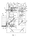
- the sample table 16 of the measuring device 10 can be moved in both the x and y directions in the plane of the sample, so that any sample 17 can be moved to the detector 11 for assay.
- the detector 11 is equipped with a height adjustment means.
- the structure of the adjustment means is not shown in Figure 1.
- the sample plates are located in the storage unit 31, from where the desired sample plate 17a can be transferred to the measuring device for measurement.
- the bar code reader 32 identifies the sample plates 17 to be transferred to the sample table of the measuring device 10.
- the light shutter 37 closes, which means that the measuring device is light-tight.
- the shutter may be underpressurised.
- the underpressurised space is filled with a small-molecule gas, such as helium, in which case the friction on the discs is low, that is, the friction of the gas molecules against the shutter discs is considerably smaller than it would be if the filler gas used in the underpressurised state was air.
- the rotational resistance also decreases and the rotating motor is able to rotate the light chopper discs faster and/or more easily, and a fast, silent device is obtained.
- the beams of light enter the sample well 39 of the sample plate 17 according to the excitation illumination method relating to the invention at the angle ⁇ 2, which is much smaller than that shown in Figure 7. This means that the sample wells at different points of the sample plate receive substantially the same amount of excitation light / illumination light.
- Figure 12 shows the mirror polyhedron 40 axonometrically.
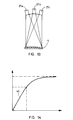
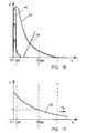
- Figure 16 shows a comparison of the durations of light pulses emitted from different types of flash lamps as a function of time.
- the lifetime curve 43 of a single powerful lamp is of long duration.
- the average pulse 44 obtained with several small lamps is of short duration.
- Figure 17 shows the duration of the fluorescence 45 of a sample.
- Figure 17 shows that the fluorescence has already been reduced to a half by the time the light from the powerful lamp has dimmed in Figure 16. This means that TR fluorescence measurement cannot be carried out efficiently by means of a single powerful flash lamp.
- Figure 16 also shows the effect of the tail light chopper 46 placed in front of the lamp for shortening the length of the light pulse. It has, however, been shown in practice that this light chopper does not improve the situation. Despite the chopper, a powerful lamp causes so much background interference that efficient TR measurement cannot be carried out.
- a light source comprises two or more flash lamps, and the measuring device comprises a timer for switching the lights on simultaneously or timed in phases as desired.
- the measuring device preferably comprises a light chopper, which is synchronised with the timer of the light source.
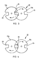
- the chopper comprises, for example, at least two rotating discs or the like, on the circumference of which, or its vicinity, there is at least one notch or opening, and which discs are positioned so as to overlap at least partly, so that as the discs rotate, the openings in the adjacent discs form the chopper aperture when they meet at the same point.
- the chopper comprises at least two discs rotating in the same direction, the said discs being mainly circular and at least two notches or openings being formed on the edges of both discs, at opposite edges of the discs.
- a solid black plate is used as a camera shutter in place of the filter in the filter wheel, by moving which plate away from the front of the camera and correspondingly to the front of the camera, a shutter-like on-off action can be obtained in the camera.
- the light emitted by the light source 15, which is continuous wave light or pulse light, is directed by means of mirrors 23 and 24 below the sample 17.
- the light source 15 comprises four flash lamps 27 which flash at different phases in order to increase optical power.
- Photometric measurement is carried out by means of a detector 11 and an emission objective 14.
- Absorption measurement is carried out by using visible light from below the sample and by means of a scattering plate 20.
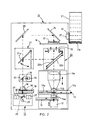
- the light source 15 is a UV light source, the light emitted by which is directed by means of mirrors 23 and 24 onto the underside of the sample 17.
- the light source 15 comprises four flash lamps 27 which flash at different phases. Since the wavelength range of the light emitted by the flash lamps 27 is wide, UV light can be directed at the sample 17 by means of the filter 18.
- a light wavelength converter plate 20 Above the sample 17 is placed a light wavelength converter plate 20, which converts the ultraviolet light into visible light, the intensity of which is measured by means of a camera and which is proportional to the amount of UV light directed at the converter plate, that is, it is proportional to the absorption of UV light.
- an opal glass may also be positioned below the sample 17. In such a case the shadow imaging of UV absorption is carried out by means of a detector 11 and an emission objective 14.
- the light source 15 of the example of an embodiment shown in Figure 5 comprises four flash lamps, where the rotational frequency of the rotating mirror is 200 Hz. This means that the interval between two successive pulses of one lamp is 5 ms. According to the invention, the lamps are controlled so that they flash at a 1.25 ms time difference with respect to each other, which means that during one 5 ms period, a total of four flashes of light are obtained.
- the combined pulse frequency of the lamps achieved with the construction described in the example is in this case 800 Hz. This is four times greater compared with that obtained with a single lamp.
- the optical power of the light source 15 is quadrupled compared with the optical power obtained with one lamp. When even greater optical power is required, the number of flash lamps can be further increased, for example, to eight flash lamps.
- the speed of rotation of the chopper 13 discs 13a and 13b is 24000 rpm, that is, the rotational frequency is 400 Hz, in other words the wheel rotates at 400 rpm. If the light chopper disc has two apertures 26, it will open 48000 times per minute, that is, 800 times per second. The opening frequency of the apertures is in that case 800 Hz.
- each individual flash lamp is triggered always at 1.25 ms intervals, which means that when the rotation is completed, 8 times 1.25 ms, that is, 10 ms have elapsed, which corresponds to a frequency of 100 Hz.
- 8 times 1.25 ms, that is, 10 ms have elapsed which corresponds to a frequency of 100 Hz.
- eight flashes of light are obtained and the combined pulse frequency of the lamps is 800 Hz.
- the frequency of a single lamp is still 100 Hz.
- One flash of light from the flash lamp occurs during each interval in the opening of the apertures of the light chopper, and during the next interval the next lamp flashes etc. What is essential is the synchronisation between the lamps and the camera. In the device relating to the example, one flash occurs between the openings of the apertures. The flash of excitation light takes place, for example, about 10 ⁇ s before the aperture begins to open.
- a dimmer and shutter may also be substituted for it.
Landscapes
- Physics & Mathematics (AREA)
- Spectroscopy & Molecular Physics (AREA)
- General Physics & Mathematics (AREA)
- Biochemistry (AREA)
- Chemical & Material Sciences (AREA)
- Analytical Chemistry (AREA)
- Life Sciences & Earth Sciences (AREA)
- General Health & Medical Sciences (AREA)
- Health & Medical Sciences (AREA)
- Immunology (AREA)
- Pathology (AREA)
- Investigating, Analyzing Materials By Fluorescence Or Luminescence (AREA)
- Investigating Materials By The Use Of Optical Means Adapted For Particular Applications (AREA)
- Investigating Or Analysing Materials By Optical Means (AREA)
Abstract
Description
Light-producing mechanisms are:
- Figure 1
- shows the device relating to the invention diagrammatically, as seen from the side.
- Figure 2
- corresponds to Figure 1 and shows a second embodiment of the device.
- Figure 3
- shows diagrammatically the shutter of the device shown in Figure 1.
- Figure 4
- corresponds to Figure 3 and shows the shutter in another position.
- Figure 5
- shows diagrammatically the light source of the device shown in Figure 1, as seen from above.
- Figure 6
- shows the light source shown in Figure 5 as seen from another direction.
- Figure 7
- shows a diagrammatic section of the sample well.
- Figure 8
- corresponds to Figure 7 and shows the sample well in another situation.
- Figure 9
- shows a diagrammatic side view of the excitation illumination of the sample plate so that the travel of the light beams emitted from one individual lamp is shown schematically.
- Figure 10
- shows a diagrammatic side view of a second embodiment of the excitation light system where there is a fixed, stationary mirror polyhedron in place of the rotating mirror.
- Figure 11
- shows a detail of Figure 10.
- Figure 12
- shows the mirror unit of the excitation light source shown in Figures 10 and 11.
- Figure 13
- shows a third embodiment of the excitation light system, which is simple, but not as compact as a system which uses a solid dividing mirror.
- Figure 14
- shows diagrammatically the principle of measuring fluorescence.
- Figure 15
- shows digarammatically an excitation and measuring principle.
- Figure 16
- shows diagrammatically an excitation illumination principle.
- Figure 17
- shows diagrammatically another measuring principle.
- a high average pulse power of the light source
- narrow light source pulse width, which is required in certain time-resolved measurements
- optical power guarantees sufficiently short measuring times in fluorescence measurement
- the intervals for changing the light source bulbs are notably long in comparison to a continuous light source
- the structure of the light source is economical in comparison to other light sources with corresponding pulse power
- the same device can be used to carry out absorption measurements of both the UV region and the visible region by imaging on extremely high-density sample plates.
Claims (23)
- An imaging device (10) for biochemical or medical samples, the said device comprisingcharacterised ina pulse mode light source (15), which includes a flash lamp (27) or a pulsed laser, which produces optionally either ultraviolet light, visible region light or infrared light,a holder (16) for the objects (17) to be imaged, which are sample matrices, gels or biological sections,a detector (11) for measuring the object (17) to be imaged,means (21-24) for directing light from the light source (15) at the sample (17),means (12-14) for directing light from the sample (17) at the detector (11),and the pulse mode light source (15) comprises flash lamps (27) or the like to illuminate and/or excite the the object (17) to be imaged,that the pulse mode light source (15) of the imaging device (10) comprises two or more flash lamps (27) or the like, which are situated on the circumference of a circle, in the centre of which there is one or more mirrors (28, 40a) in an inclined position,that the light emitted by the flash lamps (27) is directed at the mirror (28) or at the mirrors (40a) located principally in the centre of the circle,and that the mirror (28) or the mirrors (40a) are inclined into such a position that the mirror or mirrors reflect the light emitted by each flash lamp (27) principally along the same optical path from the mirror (28, 40a) to the sample (17),and that the flash lamps (27) can be switched on successively in phases or simultaneously.
- An imaging device (10) as claimed in claim 1, characterised inthat the flash lamps (27) of the light source (15) of the imaging device (10) are situated on the circumference of a circle, in the centre of which there is a rotating mirror (28) in an inclined position,that the light emitted by the flash lamps (27) is directed at the rotating mirror (28) in the centre of the circle,and that the rotating mirror (28) is inclined into such a position that, when the mirror rotates, it reflects the light emitted by each flash lamp (27) in tum along the same optical path from the mirror (28) to the sample (17).
- An imaging device (10) as claimed in claim 1 or 2, characterised inthat in the light source (15) of the imaging device (10) the flash lamps (27) are provided with condensing lenses (30),that each flash lamp (27) incorporates a triggering device for switching the flash lamps on alternately at the desired moment by phasing,that the switching-on frequency of the flash lamp (27) corresponds to the speed of rotation of the rotating mirror (28),and that the flash lamp (27) can be switched on at the exact moment when the rotating mirror (28) is at that flash lamp, so that the illuminating beam emitted from the flash lamp when it is switched on, strikes the reflecting surface of the rotating mirror and is reflected on towards the sample (17).
- An imaging device (10) as claimed in claim 1, 2 or 3, characterised inthat the speed of rotation of the rotating mirror (28) of the imaging device (10) is 6000 rpm, which means that one rotation takes 10 ms,that the light source (15) of the imaging device (10) comprises eight flash lamps (27), which are triggered at 10 ms intervals, in which case the flash frequency of a flash lamp is 100 Hz,and that in the light source (15), the flash frequency of the system of eight flash lamps (27) is 800 Hz.
- An imaging device (10) as claimed in any of the claims 1 to 4, characterised inthat the light source (15) of the imaging device (10) comprises eight flash lamps (27), the nominal power of which is 50 W,that at a flash frequency of 100 Hz, the energy supplied to one flash lamp (27) at 10 ms intervals is 0.5 J at each time of triggering, which means that the average power of the flash lamp is 50 W,and that the average total power of the system of eight flash lamps (27) of the light source (15), is eight times 50 W, that is, 400 W.
- An imaging device (10) as claimed in any of the claims 1 to 5, characterised in that the light source (15) of the imaging device (10) comprises an even number of flash lamps (27), of which at first only every other lamp is to be triggered in turn, and that the other lamps are altemated for triggering in turn as desired.
- An imaging device (10) as claimed in any of the claims 1 to 6, characterised in that the light source (15) of the imaging device (10) comprises an odd number of flash lamps (27), in which case every other lamp is triggered while the mirror (28) rotates.
- An imaging device (10) as claimed in any of the claims 1 to 7, characterised in that the imaging device (10) comprises a tail light chopper (38) which cuts off the illumination path leading from the light source (15) to the sample (17) at a predetermined moment so that the duration of the excitation light emitted from each flash lamp (27) separately to the sample (17) is of the desirable length, preventing the after-glow of the lamp from disturbing the measurement.
- An imaging device (10) as claimed in claim 8, characterised in that the tail light chopper (38) of the imaging device (10) is arranged to cut off the excitation light 3 - 30 µs, preferably 20 µs after the moment of triggering of the flash lamp (27).
- An imaging device (10) as claimed in any of the claims 1 to 9, characterised in in that the imaging device (10) comprises an emission light chopper (13), which is synchronised with the light source (15), the flash lamps (27), the rotating mirror (28) and the tail light chopper (38) so that they function together in a synchronous manner.
- An imaging device (10) as claimed in claim 10, characterised in that the emission light chopper (13) of the imaging device (10) is a mechanical rotating light chopper or a liquid crystal shutter device (LCD), which is located on the aperture plane of the imaging optics (14).
- An imaging device (10) as claimed in claim 10 or 11, characterised inthat the emission light chopper (13) of the imaging device (10) is a mechanical rotating light chopper which comprises at least two rotating discs (13a, 13b), which are mainly circular,that at least one notch or opening (25) is formed on the edge part of each rotating disc (13a, 13b),that the discs (13a, 13b) rotate in the same direction and are placed so as to partly overlap,and that the rotational movements of the discs (13a, 13b) are synchronised with respect to each other so that, when the discs rotate and the notches (25) in the different discs meet at the same point, the aperture of the light chopper is in the open position.
- An imaging device (10) as claimed in claim 10, 1 1 or 12, characterised in that the emission light chopper (13) of the imaging device (10) comprises two rotating discs (13a, 13b) on the edges of each of which are two notches (25).
- An imaging device (10) as claimed in claim 13, characterised in that the speed of rotation of the rotating discs (13a, 13b) of the emission light chopper (13) of the imaging device (10) is 24000 rpm, that is, the rotational frequency is 400 Hz, in which case each disc rotates at 400 rpm, and that there are two notches (25) in each light chopper disc (25), the said notches forming an aperture (26) which opens 48000 times per minute, that is, 800 times per second, in other words the opening frequency is 800 Hz.
- An imaging device (10) as claimed in any of the claims 10 to 14,
characterised in that the rotating discs (13a, 13b) of the emission light chopper (13) of the imaging device (10) are situated in an underpressurised space filled with air or a small-molecule gas, such as helium. - An imaging device (10) as claimed in any of the claims 1 to 15, characterised in that the imaging device (10) comprises a pulse mode light source (15) incorporating two or more flash lamps (27), an excitation objective (19), a turning mirror (21), an exchangeable mirror unit (22) including a dichroic mirror (22a) or a half-transmitting mirror (22b) which can be exchanged with one another, an emission objective lens system (14), an emission light chopper (13) and a detector (11) which is a cooled CCD camera.
- An imaging device (10) as claimed in any of the claims 1 to 16, characterised in that the emission objective lens system (14) of the imaging device (10) includes a telecentric lens system, on whose optical aperture plane is situated a light chopper (13) synchronised with the rotating mirror (28) of the light source (15).
- An imaging device (10) as claimed in any of the claims 1 to 17,characterised in that the imaging device (10) includes a turning mirror (21) for directing light from the light source (15) at the sample (17) from above and/or below.
- An imaging device (10) as claimed in any of the claims 1 to 18, characterised in that the imaging device (10) comprises a feedback photodiode (34) and a partly reflecting mirror (33), which directs some of the light emitted by each flash lamp (27) of the light source (15) at the feedback photodiode (34).
- An imaging device (10) as claimed in any of the claims 1 to 19, characterised in that the imaging device (10) comprises mirrors (23, 24) for directing the light from the light source (15) through the sample (17) to a first plate (20), which is a transparent scattering plate used for absorption measurement of visible light and UV light, or to a second plate, which is a fluorescent converter plate used for absorption measurement of UV light.
- An imaging device (10) as claimed in any of the claims 1 to 19, characterised in that the imaging device (10) comprises mirrors (23, 24) for directing the light emitted by the light source (15) through the sample (17) at an absorption measurement plate (20), which is a double-acting measurement plate, so that it is simultaneously both a transparent scattering plate used for absorption measurement of visible light and a fluorescent converter plate used for absorption measurement of UV light.
- An imaging device (10) as claimed in claim 1, characterised inthat the flash lamps (27) of the light source (15) of the imaging device (10) are situated on the circumference of a circle, in the centre of which there is a fixed mirror polyhedron (40) formed by mirrors (40a),that the mirror polyhedron (40) comprises one mirror (40a) for each flash lamp (27), all of which are switched on simultaneously,and that the light emitted by each flash lamp (27) is directed through a lens (30) towards one mirror (40a) of the mirror polyhedron (40), the said mirror being inclined to such a position that it reflects the light emitted by the flash lamp from the mirror, via the objectives, to the sample (17).
- A method for measuring biochemical or medical samples (17) by imaging, according to which methodcharacterised inthe object (17) to be imaged, such as a sample matrix, gel or biological section is illuminated and/or excited by means of a pulse mode light source (15) by using optionally either ultraviolet light, visible region light or infrared light,the illumination of the object (17) is used as the excitation light by means of which a fluorescence phenomenon is produced in the object, the emission light resulting from the phenomenon being measured at different points of the sample by means of the detector (11),or by means of the light passing through the object (17), the amount of reflection, scattering or absorption obtained through the illumination of the object is measured at different points of the sample,and the object (17) to be measured or imaged is illuminated and/or excited by means of flash lamps (27) or the like,that in order to make more efficient the illumination and/or exitation of the object (17) to be measured or imaged, the object is illuminated by means of two or more flash lamps (27) or the like situated on the circumference of a circle in the pulse mode light source (15),that the light beams emitted by the flash lamps (27) are directed at the mirror (28) or at the mirrors (40a) located principally in the centre of the circle in an inclined position,that the light beams reflected from the mirror (28) or the mirrors (40a) are directed principally along the same optical path to the sample (17).and that the flash lamps of the pulse mode light source (15) are switched on successively in phases or simultaneously.
Applications Claiming Priority (2)
| Application Number | Priority Date | Filing Date | Title |
|---|---|---|---|
| FI982005 | 1998-09-17 | ||
| FI982005A FI982005L (en) | 1998-09-17 | 1998-09-17 | Sample imaging device |
Publications (3)
| Publication Number | Publication Date |
|---|---|
| EP0987540A2 true EP0987540A2 (en) | 2000-03-22 |
| EP0987540A3 EP0987540A3 (en) | 2000-07-26 |
| EP0987540B1 EP0987540B1 (en) | 2008-08-20 |
Family
ID=8552508
Family Applications (1)
| Application Number | Title | Priority Date | Filing Date |
|---|---|---|---|
| EP99660148A Expired - Lifetime EP0987540B1 (en) | 1998-09-17 | 1999-09-17 | Sample imaging device for high-throughput screening by fluorescence measurements |
Country Status (4)
| Country | Link |
|---|---|
| US (1) | US6377346B1 (en) |
| EP (1) | EP0987540B1 (en) |
| DE (1) | DE69939357D1 (en) |
| FI (1) | FI982005L (en) |
Cited By (18)
| Publication number | Priority date | Publication date | Assignee | Title |
|---|---|---|---|---|
| WO2002068942A3 (en) * | 2001-02-28 | 2003-01-03 | Imaging Res Inc | An imaging fluorometer for time resolved fluorescence |
| EP1253446A3 (en) * | 2001-04-27 | 2004-01-28 | Wallac Oy | Screen plate of an imaging measuring instrument |
| WO2003062800A3 (en) * | 2002-01-16 | 2004-04-08 | Lockheed Corp | Portable system and method for determining one or more reflectance properties of a surface |
| DE102004016361A1 (en) * | 2004-04-01 | 2005-11-03 | Cybio Ag | Optical analyzer for fluorescence measurements on multiprobe carriers |
| WO2005068976A3 (en) * | 2004-01-14 | 2005-11-24 | Applera Corp | Apparatus and method for fluorescent detection in biological samples |
| EP1681556A1 (en) * | 2005-01-18 | 2006-07-19 | Roche Diagnostics GmbH | Imaging fluorescence signals using telecentricity |
| EP1681558A1 (en) * | 2005-01-18 | 2006-07-19 | Roche Diagnostics GmbH | Imaging fluorescence signals using telecentric optics on the excitation and the imaging side |
| EP1681555A1 (en) * | 2005-01-18 | 2006-07-19 | Roche Diagnostics GmbH | Imaging fluorescence signals using telecentric optics |
| EP1653220A3 (en) * | 2001-05-10 | 2006-08-30 | Yokogawa Electric Corporation | Biochip reader |
| US7289217B2 (en) | 2004-01-14 | 2007-10-30 | Applera Corporation | Fluorescent detector with automatic changing filters |
| EP1414517A4 (en) * | 2001-06-26 | 2008-02-06 | Photomed Technologies Inc | MULTIPLE WAVELENGTH ILLUMINATOR |
| EP2148188A1 (en) | 2008-07-25 | 2010-01-27 | F. Hoffmann-Roche AG | Excitation and imaging optics for fluorescence detection |
| EP1943498A4 (en) * | 2005-10-14 | 2010-05-05 | Univ South Florida | PORTABLE MICROARRAISER READER |
| WO2010084243A1 (en) | 2009-01-26 | 2010-07-29 | Wallac Oy | A body module for an optical measurement instrument |
| WO2010084244A1 (en) * | 2009-01-26 | 2010-07-29 | Wallac Oy | An arrangement and a method for controlling a measurement head of an optical measurement instrument |
| CN107850546A (en) * | 2015-07-30 | 2018-03-27 | 株式会社日立高新技术 | Detection device for luminescence analysis and automatic analysis device |
| EP1608955B1 (en) * | 2003-04-03 | 2020-04-29 | Bioneer Corporation | Real-time monitoring apparatus for biochemical reaction |
| US20250277255A1 (en) * | 2021-05-21 | 2025-09-04 | Timo Rapakko | A large capacity clinical assay method |
Families Citing this family (23)
| Publication number | Priority date | Publication date | Assignee | Title |
|---|---|---|---|---|
| JP4391746B2 (en) * | 2001-03-06 | 2009-12-24 | エヴォテック オーアーイー アクチエンゲゼルシャフト | Methods for testing chemical and / or biological samples |
| US6740890B1 (en) * | 2001-08-15 | 2004-05-25 | Chen-Yu Tai | Time-resolved light decay measurements without using a gated detector |
| US6800856B2 (en) * | 2001-09-20 | 2004-10-05 | Trey Enterprises Corp. | Light sampling system |
| US6924490B2 (en) * | 2002-01-10 | 2005-08-02 | Olympus Optical Co., Ltd. | Microscope system |
| FR2891924B1 (en) * | 2005-10-10 | 2007-12-28 | Biospace Mesures | LUMINESCENCE IMAGING DEVICE AND METHOD |
| FI20060495A0 (en) | 2006-05-19 | 2006-05-19 | Wallac Oy | Arrangement and procedure for illuminating an object |
| US7602488B2 (en) * | 2006-06-12 | 2009-10-13 | Neptec Optical Solutions, Inc. | High-speed, rugged, time-resolved, raman spectrometer for sensing multiple components of a sample |
| DE102007047461A1 (en) * | 2007-09-28 | 2009-04-02 | Carl Zeiss Microimaging Gmbh | Method and optical arrangement for examining a sample |
| JP2009222473A (en) * | 2008-03-14 | 2009-10-01 | Panasonic Corp | Image capturing apparatus |
| JP2009222588A (en) * | 2008-03-17 | 2009-10-01 | Panasonic Corp | Microplate reading device and microplate reading method |
| WO2010045534A1 (en) * | 2008-10-17 | 2010-04-22 | Atonometrics, Inc. | Ultraviolet light exposure chamber for photovoltaic modules |
| US8274645B2 (en) * | 2009-07-20 | 2012-09-25 | Applied Materials, Inc. | Method and apparatus for in-situ metrology of a workpiece disposed in a vacuum processing chamber |
| JP5926966B2 (en) * | 2012-01-30 | 2016-05-25 | オリンパス株式会社 | Fluorescence observation equipment |
| JP2014095594A (en) * | 2012-11-08 | 2014-05-22 | Yokogawa Electric Corp | Spectroscopic instrument and spectroscopic light source |
| US8743356B1 (en) * | 2012-11-22 | 2014-06-03 | Her Majesty The Queen In Right Of Canada As Represented By The Minister Of National Defence | Man-portable device for detecting hazardous material |
| US20140273181A1 (en) | 2013-03-15 | 2014-09-18 | Biofire Diagnostics, Inc. | Compact optical system for substantially simultaneous monitoring of samples in a sample array |
| RU2679605C2 (en) * | 2016-12-12 | 2019-02-12 | Федеральное Государственное Бюджетное Учреждение Науки Институт Молекулярной Биологии Им. В.А. Энгельгардта Российской Академии Наук (Имб Ран) | Biological microchips fluorimetric analyzer |
| CN115722286A (en) | 2017-07-18 | 2023-03-03 | 分子装置有限公司 | Object picking device with imaging-based pipette tip positioning |
| US11828879B2 (en) | 2020-07-29 | 2023-11-28 | Lg Innotek Co., Ltd. | Vibrated polarizing beam splitter for improved return light detection |
| CN112798603A (en) * | 2021-01-06 | 2021-05-14 | 深圳技术大学 | Imaging system and imaging method thereof |
| JP2024513461A (en) | 2021-04-07 | 2024-03-25 | ペンタックス・オブ・アメリカ・インコーポレイテッド | Laryngeal stroboscope using solid-state light source |
| CN115219480B (en) * | 2022-09-01 | 2022-12-16 | 合肥锁相光学科技有限公司 | A phase-locked low-light microscopic imaging method and device |
| CN119246330B (en) * | 2024-10-09 | 2025-10-28 | 集美大学 | Gel time tester and method based on light scattering effect |
Family Cites Families (8)
| Publication number | Priority date | Publication date | Assignee | Title |
|---|---|---|---|---|
| US3566119A (en) * | 1967-10-06 | 1971-02-23 | California Computer Products | Infrared scanning device using a spherical lens |
| JPS587545A (en) * | 1981-07-08 | 1983-01-17 | Olympus Optical Co Ltd | Analyzer |
| HU186069B (en) * | 1982-06-09 | 1985-05-28 | Koezponti Elelmiszeripari | Spectrophotometer operating on discrete wave-lengths |
| DE3607767C1 (en) * | 1986-03-08 | 1987-04-02 | Wolf Gmbh Richard | Video endoscope |
| EP0458601B1 (en) * | 1990-05-22 | 1996-08-28 | Research Development Corporation Of Japan | Method of and apparatus for measuring spectral absorption in opaque specimens and method of and apparatus for measuring microscopic absorption distribution |
| US5412219A (en) * | 1993-11-22 | 1995-05-02 | The United States Of America As Represented By The Administrator Of The National Aeronautics And Space Administration | Method for determining surface coverage by materials exhibiting different fluorescent properties |
| WO1998007022A1 (en) * | 1996-08-16 | 1998-02-19 | Imaging Research, Inc. | A digital imaging system for assays in well plates, gels and blots |
| AUPO551197A0 (en) * | 1997-03-07 | 1997-03-27 | Varian Australia Pty Ltd | Spectroscopic analysis method and apparatus |
-
1998
- 1998-09-17 FI FI982005A patent/FI982005L/en unknown
-
1999
- 1999-09-17 EP EP99660148A patent/EP0987540B1/en not_active Expired - Lifetime
- 1999-09-17 DE DE69939357T patent/DE69939357D1/en not_active Expired - Lifetime
- 1999-09-17 US US09/398,996 patent/US6377346B1/en not_active Expired - Lifetime
Cited By (36)
| Publication number | Priority date | Publication date | Assignee | Title |
|---|---|---|---|---|
| WO2002068942A3 (en) * | 2001-02-28 | 2003-01-03 | Imaging Res Inc | An imaging fluorometer for time resolved fluorescence |
| AU2002233598B2 (en) * | 2001-02-28 | 2007-06-14 | Ge Healthcare Niagara Inc. | An imaging fluorometer for time resolved fluorescence |
| JP2004519667A (en) * | 2001-02-28 | 2004-07-02 | イメージング リサーチ, インク. | Imaging fluorometer for time-resolved fluorescence |
| US6806455B2 (en) | 2001-02-28 | 2004-10-19 | Imaging Research Inc. | Imaging fluorometer for time resolved fluorescence |
| CN100523788C (en) * | 2001-02-28 | 2009-08-05 | Ge保健尼亚加拉公司 | Imaging fluorometer for time resolved fluorescence |
| EP1253446A3 (en) * | 2001-04-27 | 2004-01-28 | Wallac Oy | Screen plate of an imaging measuring instrument |
| US7524458B2 (en) * | 2001-04-27 | 2009-04-28 | Wallac Oy | Screen plate of an imaging measuring instrument |
| EP1653220A3 (en) * | 2001-05-10 | 2006-08-30 | Yokogawa Electric Corporation | Biochip reader |
| EP1414517A4 (en) * | 2001-06-26 | 2008-02-06 | Photomed Technologies Inc | MULTIPLE WAVELENGTH ILLUMINATOR |
| US6781697B1 (en) | 2002-01-16 | 2004-08-24 | Lockheed Martin Corporation | Portable system and method for determining one or more reflectance properties of a surface |
| WO2003062800A3 (en) * | 2002-01-16 | 2004-04-08 | Lockheed Corp | Portable system and method for determining one or more reflectance properties of a surface |
| EP1608955B1 (en) * | 2003-04-03 | 2020-04-29 | Bioneer Corporation | Real-time monitoring apparatus for biochemical reaction |
| WO2005068976A3 (en) * | 2004-01-14 | 2005-11-24 | Applera Corp | Apparatus and method for fluorescent detection in biological samples |
| US7289217B2 (en) | 2004-01-14 | 2007-10-30 | Applera Corporation | Fluorescent detector with automatic changing filters |
| US7295316B2 (en) | 2004-01-14 | 2007-11-13 | Applera Corporation | Fluorescent detector with automatic changing filters |
| DE102004016361B4 (en) * | 2004-04-01 | 2006-07-06 | Cybio Ag | Optical analyzer for fluorescence measurements on multiprobe carriers |
| DE102004016361A1 (en) * | 2004-04-01 | 2005-11-03 | Cybio Ag | Optical analyzer for fluorescence measurements on multiprobe carriers |
| US7199377B2 (en) | 2004-04-01 | 2007-04-03 | Cybio Ag | Optical analytic measurement device for fluorescence measurements in multisample carriers |
| EP1681556A1 (en) * | 2005-01-18 | 2006-07-19 | Roche Diagnostics GmbH | Imaging fluorescence signals using telecentricity |
| EP1681557A1 (en) * | 2005-01-18 | 2006-07-19 | Roche Diagnostics GmbH | Imaging of fluorescence signals using telecentric excitation and imaging optics |
| EP1681555A1 (en) * | 2005-01-18 | 2006-07-19 | Roche Diagnostics GmbH | Imaging fluorescence signals using telecentric optics |
| US7687260B2 (en) | 2005-01-18 | 2010-03-30 | Roche Diagnostics Operations, Inc. | Imaging fluorescence signals using telecentric optics |
| EP1681558A1 (en) * | 2005-01-18 | 2006-07-19 | Roche Diagnostics GmbH | Imaging fluorescence signals using telecentric optics on the excitation and the imaging side |
| US7369227B2 (en) | 2005-01-18 | 2008-05-06 | Roche Diagnostics Operations, Inc. | Imaging fluorescence signals using telecentricity |
| EP1943498A4 (en) * | 2005-10-14 | 2010-05-05 | Univ South Florida | PORTABLE MICROARRAISER READER |
| US7906767B2 (en) | 2008-07-25 | 2011-03-15 | Roche Molecular Systems, Inc. | Excitation and imaging optics for fluorescence detection |
| EP2148188A1 (en) | 2008-07-25 | 2010-01-27 | F. Hoffmann-Roche AG | Excitation and imaging optics for fluorescence detection |
| EP2148187A1 (en) | 2008-07-25 | 2010-01-27 | Roche Diagnostics GmbH | Stimulation and optical display system for fluorescence detection |
| WO2010084244A1 (en) * | 2009-01-26 | 2010-07-29 | Wallac Oy | An arrangement and a method for controlling a measurement head of an optical measurement instrument |
| US8542349B2 (en) | 2009-01-26 | 2013-09-24 | Perkinelmer Singapore Pte. Ltd. | Arrangement and a method for controlling a measurement head of an optical measurement instrument |
| CN102308219B (en) * | 2009-01-26 | 2013-10-30 | 珀金埃尔默新加坡私人有限公司 | Body module for optical measurement instrument |
| US8759789B2 (en) | 2009-01-26 | 2014-06-24 | Wallac Oy | Body module for an optical measurement instrument |
| WO2010084243A1 (en) | 2009-01-26 | 2010-07-29 | Wallac Oy | A body module for an optical measurement instrument |
| CN107850546A (en) * | 2015-07-30 | 2018-03-27 | 株式会社日立高新技术 | Detection device for luminescence analysis and automatic analysis device |
| CN107850546B (en) * | 2015-07-30 | 2020-05-12 | 株式会社日立高新技术 | Detection device and automatic analysis device for luminescence analysis |
| US20250277255A1 (en) * | 2021-05-21 | 2025-09-04 | Timo Rapakko | A large capacity clinical assay method |
Also Published As
| Publication number | Publication date |
|---|---|
| US6377346B1 (en) | 2002-04-23 |
| FI982005A0 (en) | 1998-09-17 |
| DE69939357D1 (en) | 2008-10-02 |
| EP0987540A3 (en) | 2000-07-26 |
| FI982005A7 (en) | 2000-03-18 |
| EP0987540B1 (en) | 2008-08-20 |
| FI982005L (en) | 2000-03-18 |
Similar Documents
| Publication | Publication Date | Title |
|---|---|---|
| US6377346B1 (en) | Sample imaging device | |
| FI103434B (en) | Multi-Seal Device | |
| US6043506A (en) | Multi parameter scanner | |
| US6930314B2 (en) | Light detection device | |
| RU2170420C2 (en) | Facility and method of detection of fluorescent and phosphorescent glow | |
| JPS5988646A (en) | Fluorescence photometer | |
| CA2407296A1 (en) | An imaging fluorometer for time resolved fluorescence | |
| JP2004354397A (en) | Fluorophotometer | |
| JPH04288697A (en) | Equipment and method to examine document | |
| US20070242335A1 (en) | Translational filter, shutter, aperture apparatus for selecting and combining filtered and unfiltered light | |
| JP2003207453A (en) | Fluorescence and phosphorescence measurement equipment | |
| EP1602960A1 (en) | Microscope | |
| WO2013138191A1 (en) | Solid state light source with hybrid optical and electrical intensity control | |
| JPH11511560A (en) | Analyzer | |
| US20040233545A1 (en) | Reflective optic system for imaging microplate readers | |
| US6903869B2 (en) | Illumination system for microscopy and observation or measuring method using the same | |
| JP2019508746A (en) | Imaging system and method with scattering to reduce source autofluorescence and improve uniformity | |
| US20050105080A1 (en) | Fluorometer | |
| EP3189325B1 (en) | Method and apparatus for optical measurement of a liquid sample | |
| CN206573777U (en) | A kind of column type optical chopper and spectrometer and imaging device | |
| KR100605088B1 (en) | Flat Panel Display Inspection Device | |
| KR20060025402A (en) | Optical system for multichannel sample analysis and multichannel sample analyzer | |
| CN103487375A (en) | Three-color fluorescent detector based on white-light LED | |
| CN214794466U (en) | Marker excitation and detection device | |
| JP2005055199A (en) | LED lighting device |
Legal Events
| Date | Code | Title | Description |
|---|---|---|---|
| PUAI | Public reference made under article 153(3) epc to a published international application that has entered the european phase |
Free format text: ORIGINAL CODE: 0009012 |
|
| AK | Designated contracting states |
Kind code of ref document: A2 Designated state(s): DE FR GB |
|
| AX | Request for extension of the european patent |
Free format text: AL;LT;LV;MK;RO;SI |
|
| PUAL | Search report despatched |
Free format text: ORIGINAL CODE: 0009013 |
|
| AK | Designated contracting states |
Kind code of ref document: A3 Designated state(s): AT BE CH CY DE DK ES FI FR GB GR IE IT LI LU MC NL PT SE |
|
| AX | Request for extension of the european patent |
Free format text: AL;LT;LV;MK;RO;SI |
|
| RIC1 | Information provided on ipc code assigned before grant |
Free format text: 7G 01N 21/64 A, 7G 01N 21/47 B, 7G 01N 21/66 B, 7G 01N 21/76 B |
|
| 17P | Request for examination filed |
Effective date: 20010126 |
|
| AKX | Designation fees paid |
Free format text: DE FR GB |
|
| RIN1 | Information on inventor provided before grant (corrected) |
Inventor name: KARJU, RALMO Inventor name: NURMI, JARMO Inventor name: KORPI, JARMO Inventor name: VAEISAELAE, MIKKO |
|
| RIN1 | Information on inventor provided before grant (corrected) |
Inventor name: HARJU, RAIMO Inventor name: NURMI, JARMO Inventor name: KORPI, JARMO Inventor name: VAEISAELAE, MIKKO |
|
| 17Q | First examination report despatched |
Effective date: 20060627 |
|
| GRAP | Despatch of communication of intention to grant a patent |
Free format text: ORIGINAL CODE: EPIDOSNIGR1 |
|
| RTI1 | Title (correction) |
Free format text: SAMPLE IMAGING DEVICE FOR HIGH-THROUGHPUT SCREENING BY FLUORESCENCE MEASUREMENTS |
|
| GRAS | Grant fee paid |
Free format text: ORIGINAL CODE: EPIDOSNIGR3 |
|
| GRAA | (expected) grant |
Free format text: ORIGINAL CODE: 0009210 |
|
| AK | Designated contracting states |
Kind code of ref document: B1 Designated state(s): DE FR GB |
|
| REG | Reference to a national code |
Ref country code: GB Ref legal event code: FG4D |
|
| REF | Corresponds to: |
Ref document number: 69939357 Country of ref document: DE Date of ref document: 20081002 Kind code of ref document: P |
|
| PLBE | No opposition filed within time limit |
Free format text: ORIGINAL CODE: 0009261 |
|
| STAA | Information on the status of an ep patent application or granted ep patent |
Free format text: STATUS: NO OPPOSITION FILED WITHIN TIME LIMIT |
|
| 26N | No opposition filed |
Effective date: 20090525 |
|
| REG | Reference to a national code |
Ref country code: FR Ref legal event code: PLFP Year of fee payment: 17 |
|
| REG | Reference to a national code |
Ref country code: FR Ref legal event code: PLFP Year of fee payment: 18 |
|
| REG | Reference to a national code |
Ref country code: FR Ref legal event code: PLFP Year of fee payment: 19 |
|
| REG | Reference to a national code |
Ref country code: FR Ref legal event code: PLFP Year of fee payment: 20 |
|
| PGFP | Annual fee paid to national office [announced via postgrant information from national office to epo] |
Ref country code: DE Payment date: 20180927 Year of fee payment: 20 Ref country code: FR Payment date: 20180925 Year of fee payment: 20 |
|
| PGFP | Annual fee paid to national office [announced via postgrant information from national office to epo] |
Ref country code: GB Payment date: 20180927 Year of fee payment: 20 |
|
| REG | Reference to a national code |
Ref country code: DE Ref legal event code: R071 Ref document number: 69939357 Country of ref document: DE |
|
| REG | Reference to a national code |
Ref country code: GB Ref legal event code: PE20 Expiry date: 20190916 |
|
| PG25 | Lapsed in a contracting state [announced via postgrant information from national office to epo] |
Ref country code: GB Free format text: LAPSE BECAUSE OF EXPIRATION OF PROTECTION Effective date: 20190916 |