EP0987435A2 - Spark plug ignition coil assembly for direct ignition system - Google Patents
Spark plug ignition coil assembly for direct ignition system Download PDFInfo
- Publication number
- EP0987435A2 EP0987435A2 EP99117884A EP99117884A EP0987435A2 EP 0987435 A2 EP0987435 A2 EP 0987435A2 EP 99117884 A EP99117884 A EP 99117884A EP 99117884 A EP99117884 A EP 99117884A EP 0987435 A2 EP0987435 A2 EP 0987435A2
- Authority
- EP
- European Patent Office
- Prior art keywords
- ignition coil
- spark plug
- end portion
- insulator
- coil assembly
- Prior art date
- Legal status (The legal status is an assumption and is not a legal conclusion. Google has not performed a legal analysis and makes no representation as to the accuracy of the status listed.)
- Granted
Links
- 239000012212 insulator Substances 0.000 claims abstract description 55
- 238000010068 moulding (rubber) Methods 0.000 claims abstract description 31
- 230000002093 peripheral effect Effects 0.000 claims description 10
- 238000009413 insulation Methods 0.000 claims description 6
- 230000006835 compression Effects 0.000 description 6
- 238000007906 compression Methods 0.000 description 6
- 230000006866 deterioration Effects 0.000 description 5
- 230000008878 coupling Effects 0.000 description 3
- 238000010168 coupling process Methods 0.000 description 3
- 238000005859 coupling reaction Methods 0.000 description 3
- XEEYBQQBJWHFJM-UHFFFAOYSA-N Iron Chemical group [Fe] XEEYBQQBJWHFJM-UHFFFAOYSA-N 0.000 description 2
- PNEYBMLMFCGWSK-UHFFFAOYSA-N aluminium oxide Inorganic materials [O-2].[O-2].[O-2].[Al+3].[Al+3] PNEYBMLMFCGWSK-UHFFFAOYSA-N 0.000 description 2
- 230000002542 deteriorative effect Effects 0.000 description 2
- 230000000694 effects Effects 0.000 description 2
- 239000000919 ceramic Substances 0.000 description 1
- 238000002485 combustion reaction Methods 0.000 description 1
- 230000004048 modification Effects 0.000 description 1
- 238000012986 modification Methods 0.000 description 1
- 239000012260 resinous material Substances 0.000 description 1
Images


Classifications
-
- F—MECHANICAL ENGINEERING; LIGHTING; HEATING; WEAPONS; BLASTING
- F02—COMBUSTION ENGINES; HOT-GAS OR COMBUSTION-PRODUCT ENGINE PLANTS
- F02P—IGNITION, OTHER THAN COMPRESSION IGNITION, FOR INTERNAL-COMBUSTION ENGINES; TESTING OF IGNITION TIMING IN COMPRESSION-IGNITION ENGINES
- F02P3/00—Other installations
- F02P3/02—Other installations having inductive energy storage, e.g. arrangements of induction coils
Definitions
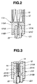
- An ignition coil 12 is disposed above the spark plug 20.
- the ignition coil 12 has an iron core 13 at the center thereof and is disposed vertically.
- a rubber molding 15 embeds therein the ignition coil 12 so as to cooperate with the ignition coil 12 to constitute an integral unit.
- the rubber molding 15 has a hollow lower end portion 15A in which the upper end portion 21A of the insulator 21 is fitted.
- the hollow lower end portion 15A has at an inner periphery thereof a projection or smaller diameter section 15B.
- the inner periphery of the lower end portion 15A serves as a second joining section joined with the above described first joining section, i.e., the outer periphery of the upper end portion 21A of the insulator 21.
- the upper end portion 21A of the insulator 21 is fitted in the hollow lower end portion 15A of the rubber molding 15, while allowing the projection or smaller diameter inner peripheral section 15B of the rubber molding 15 to engage in the recess or smaller diameter outer peripheral section 21C of the insulator 21.
- the ignition coil 12 and the spark plug 20 are firmly joined together.
- the end of the connecting terminal 14 in the form of a needle is held assuredly in contact with the terminal 22, whereby it becomes possible to supply a high voltage produced by the ignition coil 21 to the spark plug 20 assuredly.
- Fig. 2 shows a spark plug and ignition coil assembly according to the second embodiment of the present invention.
- a hollow upper end portion of an insulator of a spark plug has an outer periphery serving as a first joining section, a hollow lower end portion of a rubber molding which embeds therein an ignition coil so as to cooperates with the ignition coil to constitute an integral unit has an inner periphery serving as a second joining section which is joined with the first joining section, and a fastening means is provided for fastening the first and second joining sections together, so the ignition coil and the spark plug are joined together with a large joining force so that leakage hardly occurs even if deterioration of the rubber molding occurs to sane extent.
Landscapes
- Engineering & Computer Science (AREA)
- Chemical & Material Sciences (AREA)
- Combustion & Propulsion (AREA)
- Mechanical Engineering (AREA)
- General Engineering & Computer Science (AREA)
- Ignition Installations For Internal Combustion Engines (AREA)
- Spark Plugs (AREA)
Abstract
Description
Claims (15)
- A spark plug and ignition coil assembly (11) for a direct ignition system comprising:a spark plug (20) having an insulator (21);said insulator (21) having a hollow upper end portion (21A; 121A; 221A) having at an outer periphery thereof a first joining section;an ignition coil (12); anda rubber molding (15) embedding therein said ignition coil (12) so as to cooperate with said ignition coil (12) to constitute an integral unit;said rubber molding (15) having a hollow lower end portion (15A; 115A; 215A)in which said upper end portion (21A; 121A; 221A) of said insulator (21) is fitted;said lower end portion (15A: 115A; 215A))of said rubber molding (15) having at an inner periphery there of a second joining section joined with said first engagement section;fastening means (15B, 21C; 115B, 121C; 215B, 221C) for fastening said first and second joining sections together.
- A spark plug and ignition coil assembly (11) according to claim 1, wherein said fastening means comprises a projection (15B; 121C; 215B) provided to one of said first and second joining sections and a recess (21C; 115B; 221C) provided to the other of said first and second joining sections.
- A spark plug and ignition coil assembly according to claim 2, wherein said projection (121C) and said recess (115B) are annular and have a trapezoidal cross section.
- A spark plug and ignition coil assembly according to claim 2, wherein said projection (215B) and said recess (221C) are annular and have a rectangular cross section.
- A spark plug and ignition coil assembly according to claim 1, wherein said upper end portion (21A; 121A; 221A) of said insulator (21) is hollow, said spark plug (20) having a terminal (22) positioned entirely inside said upper end portion (21A; 121A; 221A) of said insulator (21).
- A spark plug and ignition coil assembly (11) according to claim 5, further comprising a connecting terminal (14; 17) electrically connecting between said terminal (22) of said spark plug (20) and said ignition coil (12).
- A spark plug and ignition coil assembly (11) according to claim 6, further comprising an insulation sleeve (18) extending away from said ignition coil (12) and protruding partly into said upper end portion (221A) of said insulator (21) so as to surround said connecting terminal (17).
- A spark plug and ignition coil assembly (11) according to claim 6, wherein said connecting terminal (14) is in the form of a needle.
- A spark plug and ignition coil assembly according to claim 6, wherein said connecting terminal (17) is in the form of a coil spring.
- A spark plug and ignition coil assembly (11) for a direct ignition system comprising:a spark plug (20) having an insulator (21);said insulator (21) having a hollow upper end portion (21A; 121A; 221A) having a larger diameter outer peripheral section (121C) and a smaller diameter outer peripheral section (21C; 221C);an ignition coil (12); anda rubber molding (15) embedding therein said ignition coil so as to cooperate with said ignition coil (12) to constitute an integral unit;said rubber molding (15) having a hollow lower end portion (15A; 115A; 215A) in which said upper end portion (21A; 121A; 221A) of said insulator (21) is fitted;said lower end portion (15A; 115A; 215A) of said rubber molding (15) having a larger diameter inner peripheral portion (115B) and a smaller diameter inner peripheral portion (15B; 215B) which are respectively joined with said larger diameter outer peripheral section (121C) and said smaller diameter outer peripheral section (21C; 221C) of said upper end portion (21A) of said insulator (21) so that said lower end portion (15A; 115A; 215A)) of said rubber molding (15) and said upper end portion (21A; 121A; 221A) of said insulator (21) are fastened together.
- A spark plug and ignition coil assembly (11) according to claim 10, wherein said upper end portion (21A) of said insulator (21) is hollow, said spark plug (20) having a terminal (22) which is disposed so as to have an upper end positioned inside said upper end portion (21A; 121A; 221A) of said insulator (21).
- A spark plug and ignition coil assembly (11) according to claim 11, further comprising a connecting terminal (14; 17) electrically connecting between said terminal (22) of said spark plug (20) and said ignition coil (12).
- A spark plug and ignition coil assembly (11) according to claim 12, further comprising an insulation sleeve (18) extending away from said ignition coil (12) and protruding partly into said upper end portion (221A) of said insulator (21) so as to surround said connecting terminal (17).
- A spark plug and ignition coil assembly according to claim 12, wherein said connecting terminal (14) is in the form of a needle.
- A spark plug and ignition coil assembly according to claim 12, wherein said connecting terminal (17) is in the form of a coil spring.
Applications Claiming Priority (2)
| Application Number | Priority Date | Filing Date | Title |
|---|---|---|---|
| JP25969798 | 1998-09-14 | ||
| JP10259697A JP2000091057A (en) | 1998-09-14 | 1998-09-14 | Direct ignition type plug |
Publications (3)
| Publication Number | Publication Date |
|---|---|
| EP0987435A2 true EP0987435A2 (en) | 2000-03-22 |
| EP0987435A3 EP0987435A3 (en) | 2002-06-19 |
| EP0987435B1 EP0987435B1 (en) | 2005-02-16 |
Family
ID=17337680
Family Applications (1)
| Application Number | Title | Priority Date | Filing Date |
|---|---|---|---|
| EP19990117884 Expired - Lifetime EP0987435B1 (en) | 1998-09-14 | 1999-09-10 | Spark plug ignition coil assembly for direct ignition system |
Country Status (3)
| Country | Link |
|---|---|
| EP (1) | EP0987435B1 (en) |
| JP (1) | JP2000091057A (en) |
| DE (1) | DE69923739T2 (en) |
Cited By (5)
| Publication number | Priority date | Publication date | Assignee | Title |
|---|---|---|---|---|
| US6675785B2 (en) | 2002-04-01 | 2004-01-13 | Denso Corporation | Ignition device for an internal combustion engine |
| US6698411B2 (en) | 2002-04-01 | 2004-03-02 | Denso Corporation | Ignition device for internal combustion engine |
| US7017566B2 (en) | 2002-04-01 | 2006-03-28 | Denso Corporation | Ignition device for an internal combustion engine |
| WO2013172771A1 (en) | 2012-05-14 | 2013-11-21 | Sem Ab | Spark plug extension |
| WO2018234095A1 (en) | 2017-06-19 | 2018-12-27 | Sem Ab | EXTENSION OF IGNITION CANDLE |
Families Citing this family (5)
| Publication number | Priority date | Publication date | Assignee | Title |
|---|---|---|---|---|
| KR20020001305A (en) * | 2000-06-28 | 2002-01-09 | 배길훈 | Boot assembly of ignition coil in vehicle |
| KR100560758B1 (en) * | 2001-12-10 | 2006-03-13 | 한국델파이주식회사 | Automotive Ignition Coil |
| JP5012753B2 (en) * | 2007-10-31 | 2012-08-29 | 株式会社デンソー | Ignition coil and manufacturing method thereof |
| JP4978488B2 (en) * | 2008-01-30 | 2012-07-18 | 株式会社デンソー | Ignition coil manufacturing method |
| JP6259624B2 (en) * | 2013-09-30 | 2018-01-10 | 株式会社Soken | Ignition device |
Family Cites Families (4)
| Publication number | Priority date | Publication date | Assignee | Title |
|---|---|---|---|---|
| JPS60195374A (en) * | 1984-03-16 | 1985-10-03 | Sawafuji Electric Co Ltd | Ignition device for internal-combustion engine |
| JPS6375358A (en) * | 1986-09-18 | 1988-04-05 | Nippon Denso Co Ltd | Ignition device for internal combustion engine |
| JP3277750B2 (en) * | 1995-04-26 | 2002-04-22 | 三菱電機株式会社 | Transmission device and ignition device for ignition device of internal combustion engine |
| JP3115240B2 (en) * | 1996-09-11 | 2000-12-04 | 株式会社日立製作所 | Ignition device for internal combustion engine |
-
1998
- 1998-09-14 JP JP10259697A patent/JP2000091057A/en active Pending
-
1999
- 1999-09-10 EP EP19990117884 patent/EP0987435B1/en not_active Expired - Lifetime
- 1999-09-10 DE DE69923739T patent/DE69923739T2/en not_active Expired - Lifetime
Cited By (6)
| Publication number | Priority date | Publication date | Assignee | Title |
|---|---|---|---|---|
| US6675785B2 (en) | 2002-04-01 | 2004-01-13 | Denso Corporation | Ignition device for an internal combustion engine |
| US6698411B2 (en) | 2002-04-01 | 2004-03-02 | Denso Corporation | Ignition device for internal combustion engine |
| US7017566B2 (en) | 2002-04-01 | 2006-03-28 | Denso Corporation | Ignition device for an internal combustion engine |
| WO2013172771A1 (en) | 2012-05-14 | 2013-11-21 | Sem Ab | Spark plug extension |
| US10164410B2 (en) | 2012-05-14 | 2018-12-25 | Sem Ab | Spark plug extension |
| WO2018234095A1 (en) | 2017-06-19 | 2018-12-27 | Sem Ab | EXTENSION OF IGNITION CANDLE |
Also Published As
| Publication number | Publication date |
|---|---|
| EP0987435B1 (en) | 2005-02-16 |
| EP0987435A3 (en) | 2002-06-19 |
| JP2000091057A (en) | 2000-03-31 |
| DE69923739T2 (en) | 2005-07-07 |
| DE69923739D1 (en) | 2005-03-24 |
Similar Documents
| Publication | Publication Date | Title |
|---|---|---|
| US6655334B2 (en) | Ignition apparatus for use in internal combustion engine | |
| US6259344B1 (en) | Ignition component for internal combustion engines | |
| EP0987435B1 (en) | Spark plug ignition coil assembly for direct ignition system | |
| JP2006324515A (en) | Ignition device for internal combustion engine | |
| KR102869048B1 (en) | Dual sprrk plug | |
| US6880540B2 (en) | Ignition coil, and internal combustion engine ignition device | |
| US6810868B2 (en) | Ignition coil for internal combustion engine | |
| US7243643B2 (en) | Ignition device for internal combustion engine | |
| JP3864872B2 (en) | Ignition device for internal combustion engine | |
| JP4463389B2 (en) | Method for manufacturing ignition device for internal combustion engine | |
| US20100007257A1 (en) | Spark Plug | |
| US7150274B2 (en) | Ignition device for internal combustion engine | |
| JP4701835B2 (en) | Stick type ignition coil | |
| US7075400B2 (en) | Electrical contacting of thin enameled wires of secondary windings of ignition coils | |
| KR100491622B1 (en) | An ignition device for an internal combustion engine | |
| JP4441872B2 (en) | Stick-type ignition coil and cylindrical member thereof | |
| JP4019766B2 (en) | Ignition device for internal combustion engine and method of assembling the same | |
| JPH0233473A (en) | Plug cap for ignition coil | |
| JP3838138B2 (en) | Ignition device for internal combustion engine | |
| JP3526826B2 (en) | Ignition coil device for internal combustion engine | |
| JPH045896Y2 (en) | ||
| CN100353469C (en) | Stick ignition coil apparatus for ignition plug | |
| JPH0347475A (en) | Ignition coil | |
| JPH1116753A (en) | Ignition coil for internal combustion engine | |
| KR100525662B1 (en) | An ignition device for an internal combustion engine |
Legal Events
| Date | Code | Title | Description |
|---|---|---|---|
| PUAI | Public reference made under article 153(3) epc to a published international application that has entered the european phase |
Free format text: ORIGINAL CODE: 0009012 |
|
| AK | Designated contracting states |
Kind code of ref document: A2 Designated state(s): AT BE CH CY DE DK ES FI FR GB GR IE IT LI LU MC NL PT SE |
|
| AX | Request for extension of the european patent |
Free format text: AL;LT;LV;MK;RO;SI |
|
| PUAL | Search report despatched |
Free format text: ORIGINAL CODE: 0009013 |
|
| AK | Designated contracting states |
Kind code of ref document: A3 Designated state(s): AT BE CH CY DE DK ES FI FR GB GR IE IT LI LU MC NL PT SE |
|
| AX | Request for extension of the european patent |
Free format text: AL;LT;LV;MK;RO;SI |
|
| 17P | Request for examination filed |
Effective date: 20020709 |
|
| AKX | Designation fees paid |
Designated state(s): DE FR GB IT |
|
| 17Q | First examination report despatched |
Effective date: 20040326 |
|
| GRAP | Despatch of communication of intention to grant a patent |
Free format text: ORIGINAL CODE: EPIDOSNIGR1 |
|
| GRAS | Grant fee paid |
Free format text: ORIGINAL CODE: EPIDOSNIGR3 |
|
| GRAA | (expected) grant |
Free format text: ORIGINAL CODE: 0009210 |
|
| AK | Designated contracting states |
Kind code of ref document: B1 Designated state(s): DE FR GB IT |
|
| REG | Reference to a national code |
Ref country code: GB Ref legal event code: FG4D |
|
| REG | Reference to a national code |
Ref country code: IE Ref legal event code: FG4D |
|
| REF | Corresponds to: |
Ref document number: 69923739 Country of ref document: DE Date of ref document: 20050324 Kind code of ref document: P |
|
| PG25 | Lapsed in a contracting state [announced via postgrant information from national office to epo] |
Ref country code: GB Free format text: LAPSE BECAUSE OF NON-PAYMENT OF DUE FEES Effective date: 20050910 |
|
| PLBE | No opposition filed within time limit |
Free format text: ORIGINAL CODE: 0009261 |
|
| STAA | Information on the status of an ep patent application or granted ep patent |
Free format text: STATUS: NO OPPOSITION FILED WITHIN TIME LIMIT |
|
| ET | Fr: translation filed | ||
| 26N | No opposition filed |
Effective date: 20051117 |
|
| GBPC | Gb: european patent ceased through non-payment of renewal fee |
Effective date: 20050910 |
|
| PGFP | Annual fee paid to national office [announced via postgrant information from national office to epo] |
Ref country code: IT Payment date: 20080927 Year of fee payment: 10 |
|
| PGFP | Annual fee paid to national office [announced via postgrant information from national office to epo] |
Ref country code: DE Payment date: 20090903 Year of fee payment: 11 |
|
| PGFP | Annual fee paid to national office [announced via postgrant information from national office to epo] |
Ref country code: FR Payment date: 20091012 Year of fee payment: 11 |
|
| PG25 | Lapsed in a contracting state [announced via postgrant information from national office to epo] |
Ref country code: IT Free format text: LAPSE BECAUSE OF NON-PAYMENT OF DUE FEES Effective date: 20090910 |
|
| REG | Reference to a national code |
Ref country code: FR Ref legal event code: ST Effective date: 20110531 |
|
| REG | Reference to a national code |
Ref country code: DE Ref legal event code: R119 Ref document number: 69923739 Country of ref document: DE Effective date: 20110401 |
|
| PG25 | Lapsed in a contracting state [announced via postgrant information from national office to epo] |
Ref country code: FR Free format text: LAPSE BECAUSE OF NON-PAYMENT OF DUE FEES Effective date: 20100930 Ref country code: DE Free format text: LAPSE BECAUSE OF NON-PAYMENT OF DUE FEES Effective date: 20110401 |