EP0987109A1 - Automatic obturation device for through holes for air in a cylinder, particularly for support cylinders and compensating sleeves - Google Patents
Automatic obturation device for through holes for air in a cylinder, particularly for support cylinders and compensating sleeves Download PDFInfo
- Publication number
- EP0987109A1 EP0987109A1 EP99450021A EP99450021A EP0987109A1 EP 0987109 A1 EP0987109 A1 EP 0987109A1 EP 99450021 A EP99450021 A EP 99450021A EP 99450021 A EP99450021 A EP 99450021A EP 0987109 A1 EP0987109 A1 EP 0987109A1
- Authority
- EP
- European Patent Office
- Prior art keywords
- valve
- seat
- support
- cylinder
- sleeve
- Prior art date
- Legal status (The legal status is an assumption and is not a legal conclusion. Google has not performed a legal analysis and makes no representation as to the accuracy of the status listed.)
- Granted
Links
Images


Classifications
-
- B—PERFORMING OPERATIONS; TRANSPORTING
- B41—PRINTING; LINING MACHINES; TYPEWRITERS; STAMPS
- B41F—PRINTING MACHINES OR PRESSES
- B41F27/00—Devices for attaching printing elements or formes to supports
- B41F27/14—Devices for attaching printing elements or formes to supports for attaching printing formes to intermediate supports, e.g. adapter members
-
- B—PERFORMING OPERATIONS; TRANSPORTING
- B41—PRINTING; LINING MACHINES; TYPEWRITERS; STAMPS
- B41F—PRINTING MACHINES OR PRESSES
- B41F27/00—Devices for attaching printing elements or formes to supports
- B41F27/10—Devices for attaching printing elements or formes to supports for attaching non-deformable curved printing formes to forme cylinders
- B41F27/105—Devices for attaching printing elements or formes to supports for attaching non-deformable curved printing formes to forme cylinders for attaching cylindrical printing formes
Definitions
- the present invention relates to an automatic shutter device air passage holes in a cylinder, especially for cylinders support and compensation sleeves.
- the support cylinder is hollow and forms a closed enclosure.
- a pressurized air supply to this closed enclosure is provided at one of the ends while nozzles, generally distributed along a generator, release this pressurized air.
- the first hole creates a film of pressurized air at the interface, radially expands the sleeve; which, like a cushion of air, allows the introduction of this sleeve over the entire length of the cylinder, if need.
- the sleeve returns to its nominal diameter and the radial clamping forces are sufficient for the keep in place, even in operation, during rotation.
- the use of a compensating sleeve is of interest certain.
- a compensation sleeve then on this sleeve compensation, a printing sleeve with its plate or engraving. From this fact, the difference in thickness corresponding to given developments is distributed over the two compensation and printing sleeves.
- the printing sleeves are made of composite material and the thicknesses are generally limited for weight reasons because even if the composite is much lighter than steel, you have to stay in sleeve weights 15 kg final weight so that they can be handled by just one person. This limits its thickness.
- the only other alternative to the compensating sleeve would be to have a large fleet of hollow support cylinders with all dimensions suitable for different diameters of printing sleeves. This would allow limit the thickness of the printing sleeve by choosing a cylinder larger diameter support. But in this case, it's the support cylinders which have to be changed, which is particularly delicate and time consuming because of the weight which makes them very heavy to maneuver. In addition, the cost of park is very strongly increased, which makes this solution totally inadequate.
- a first problem which arises arises from the fact that the holes are distributed along a generator and all open, which generates a poor pressure distribution. Indeed, if the first holes are clogged, pressurized air tends to carry over other holes and limit the formation of an air film between the sleeve and the cylinder. Pressure limited leads to less radial expansion and strength mounting. If the pressure is too high, it risks at the end of assembly where all the holes are closed to degrade the sleeve, which is not a solution satisfactory.
- the object of the invention is to overcome these problems and to allow a easy fitting of sleeves, either in the case of a single sleeve directly on the support cylinder, i.e. in the case of a compensation sleeve with coaxial printing sleeve.
- the solution must be feasible at costs low for the equipment of the existing fleet and at low additional costs for the new.
- the automatic shut-off device for through holes of air in a cylinder according to the invention in particular for the support cylinders sleeves and for compensating sleeves, includes, inserted in the thickness of the wall of this cylinder, a support, a seat with a passage interior and a valve movable in translation in the support and capable of take two positions, the first in which the valve comes into contact watertight with said seat and the other in which it is recessed so as to leave a passage, this valve having a cone-shaped head and a seat provided with an interior passage of shape combined with that of the head for ensure a seal when the head is pressed against the seat, in the interior passage, slightly projecting from the exterior surface and a position in which the head is set back from the seat, leaving thus a passage.
- the valve has a head with a flange provided for come to press tightly against the face opposite the seat as well an element forming a stop by angular displacement, so as to ensure sealing when the stop member is in a first position angular and generate a passage by withdrawal of the flange relative to the seat when the stop member is in a second angular position.
- the stopper element is a pin.
- the different elements, support / seat / valve are mounted in an insert intended to be added in the thickness of the cylinder.
- the cylinder 10 is a metal support cylinder which is hollow and comprises at each of its two ends an axis 12, 14 of rotation, both intended to cooperate with machine bearings, this known way.
- One 14 of the axes includes a central bore with a tip quick connection (not shown) to connect the enclosure 16 constituted by the interior from the cylinder to a source 15 of pressurized air.
- this cylinder comprises a particular distribution which is optimized, without being limiting, with a first set 18 of 6 nozzles regularly distributed at the periphery on the same circle and several games 20 secondary nozzles identical to those of the first game, distributed at the periphery of successive circles along a generatrix.
- This compensating sleeve 22 includes a first set 24 of nozzles regularly distributed as the support cylinder nozzles, as well as several secondary games 26 similar to the secondary games of the support cylinder.
- Each nozzle of each compensating sleeve is equipped with 28 individual means of automatically closing each nozzle of each different games.
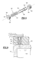
- Each shutter 30 comprises a support 32, a seat 34 and a movable valve 36.
- the support 32 is a ring 38 whose internal passage 40 is flanked, in this case 6 sides.
- the seat 34 is a ring 44, fixed in a bore 46, flush exterior side.
- This ring 44 has an interior passage 48 of conical shape as shown in figure 5.
- the movable valve 36 comprises a body 50 having a diameter allowing the sliding in the inner passage 40 with sides of the ring and a head 52 of profile combined with that of the interior passage 48 of shape conical ring 44 of the seat.
- This valve can take two positions, one in which the valve is recessed, with the head 52 outside the passage interior 48 and the other in which the valve is supported, with the head 52 pressed against the wall of the conical interior passage, thus ensuring sealing.
- a spring 54 is interposed between the support 38 and the head 52 of the valve 36 so as to press this valve against the seat 34.
- the stiffness of this spring is relatively weak since its role is limited to compensating for the weight the valve to hold it against the seat when the valve is under gravity in the head / body direction.
- the inner enclosure 16 of the support cylinder 10 is pressurized if although air escapes through sets 18 and 20 of nozzles.
- the compensation sleeve is inserted which hides the nozzles of the first set 18 of nozzles.
- An air film is generated between the surface of the support cylinder and the inner surface of the compensation. Balancing is partly improved by the fact that the nozzles are distributed asymmetrically with a larger number upon entry, without increasing pressure.
- the support cylinders are made of metal and the sleeves are made of composite material, so the coefficient of friction is acceptable and the compensation sleeve is easy to mount.
- the following step consists in coaxially inserting a printing sleeve 56 bearing a plate or an engraving 58, on the compensation sleeve 22 which comes to be mounted on the support cylinder.
- the pressurized air supply is interrupted, which which immobilizes the compensation sleeve on the cylinder support.
- the printing sleeve is then introduced through its end onto the compensation sleeve, until covering the nozzles of the first set.
- the valves of the individual automatic shutters of the nozzles of this first game retracts to allow passage through the nozzles of the first game.
- the pressurized air supply is then resumed. Air under pressure passes through the nozzles of the support cylinder and through the plugs open the compensating sleeve, to create an air film between this compensation sleeve which is stationary and the printing sleeve at introduce.
- the valves are open which improves the distribution of the pressurized air film at the interface.
- the power supply pressurized air is interrupted which ensures the immobilization of the printing sleeve on the compensation sleeve, itself immobilized on the support cylinder.
- Figure 6 is an alternative embodiment of the valve whose body is provided with a longitudinal blind hole and radial air passage holes.
- the valve body remains in abutment on the support without passing through it.
- Guidance is then obtained in this particular embodiment by the differences between the dimensions of the valve body and those of the overbore in which it is movable in translation and by the coaxial spring.
- FIGS. 7A and 7B a locking variant has been shown. manual, identical references bearing the same augmented references of 100.
- This variant provides for a movable valve 136 which is pushed by a spring 154 as in the previous assembly.
- the ring 138 is identical to the previous ring 38, with an internal passage 140 with a hexagon for allow the body 150 of the valve to slide.
- This body 150 has a end 151 which is of form conjugate with that of the hole made in the support cylinder 10 for indexing.
- the ring 144 of the seat 134 is of simple shape with passage 148 inside cylindrical, combined with that of the body 150 of the valve.
- a collar 153 forming a stopper is added to the body and secured to it to avoid passage of this body 150 of the valve through the passage 148 and especially for form a seal with the face opposite the seat 134.
- This arrangement also provides means 160 for locking in position which include a pin 162, arranged transversely to the body 150 of the valve, immediately above the flange 153, provided to cooperate with an open housing 164, of form adapted to receive this pin in a given first angular position.
- the valve In this position shown in FIG. 7A, the valve is in position high and the collar seals with the face opposite the ring 144 of the seat 134.
- the pressurized air reinforces this plating effect.
- an air film is formed between the sleeve 22 and this cylinder support 10, in the case where the enclosure 16 constituted by the hollow interior of the support cylinder is supplied with pressurized air.
- the valve When the sleeve must be immobilized, it is enough, after positioning the sleeve relative to the support cylinder by means of external marks, rotate the valve, using a simple screwdriver blade for example, a slot 166 being formed at the end of the valve on the head 152.
- the valve once turned angularly, has an offset between the pin 162 and the housing 164 provided for receiving it, so that the valve is kept in the open position because the flange is moved away from the face of the seat ring on which it was resting.
- the end 151 of the valve body enters the hole in the support cylinder, which allows a check of the correct indexing.
- the compensation sleeve is thus positioned and immobilized on the support cylinder 10.
- the pressurized air admitted into the enclosure 16 formed by the hollow body of this cylinder passes through the sleeve of compensation which allows the mounting of the printing sleeve with its snapshot, easily, as in the main embodiment.
- the sealing means are mounted directly on the support cylinder because this improves the pressure distribution and makes it possible to obtain an air film of best quality.
- the shutters are then directly introduced into the thickness of the cylinder.
- an insert which is screwed into a threaded hole machined in the thickness of the wall of the cylinder, said insert comprising all of the elements support / seat / valve / spring which have just been described for the sleeve compensation.
- valve can be produced by means a valve according to the invention because it suffices to orient the assembly support / seat / valve upside down and mount a stiffer spring, calibrated to correspond to a given maximum pressure.
Landscapes
- Supply, Installation And Extraction Of Printed Sheets Or Plates (AREA)
- Self-Closing Valves And Venting Or Aerating Valves (AREA)
Abstract
Description
La présente invention concerne un dispositif d'obturation automatique de trous de passage d'air dans un cylindre, notamment pour les cylindres support et les manchons de compensation.The present invention relates to an automatic shutter device air passage holes in a cylinder, especially for cylinders support and compensation sleeves.
On connaít des moyens pour monter des manchons sur des cylindres creux. Ces moyens consistent à réaliser et utiliser des manchons qui sont ajustés serrés par rapport au cylindre support et qui sont montés sur ledit cylindre par génération d'un film d'air sous pression dans la zone interface. A cet effet, le cylindre support est creux et forme une enceinte close. Une alimentation en air sous pression de cette enceinte close est prévue à une des extrémités tandis que des ajutages, généralement répartis suivant une génératrice, permettent de libérer cet air sous pression. Dès l'emboítement coaxial du manchon, le premier trou crée un film d'air sous pression à l'interface, dilate radialement le manchon ; ce qui, à la façon d'un coussin d'air, permet l'introduction de ce manchon sur toute la longueur du cylindre, si besoin.We know ways to mount sleeves on cylinders hollow. These means consist in making and using sleeves which are adjusted tight relative to the support cylinder and which are mounted on said cylinder by generation of a pressurized air film in the interface area. AT For this purpose, the support cylinder is hollow and forms a closed enclosure. A pressurized air supply to this closed enclosure is provided at one of the ends while nozzles, generally distributed along a generator, release this pressurized air. From the nest coaxial of the sleeve, the first hole creates a film of pressurized air at the interface, radially expands the sleeve; which, like a cushion of air, allows the introduction of this sleeve over the entire length of the cylinder, if need.
Dès l'interruption de l'alimentation en air sous pression, le manchon reprend son diamètre nominal et les efforts radiaux de serrage suffisent pour le maintenir en place, même en fonctionnement, durant la rotation.As soon as the pressurized air supply is interrupted, the sleeve returns to its nominal diameter and the radial clamping forces are sufficient for the keep in place, even in operation, during rotation.
Si ce type de montage est bien connu, il se pose un problème quand il est nécessaire de monter, de façon coaxiale superposées, deux manchons sur un même cylindre creux. If this type of assembly is well known, there is a problem when it it is necessary to mount, in a coaxial way superimposed, two sleeves on the same hollow cylinder.
En effet, pour pouvoir monter un manchon d'impression d'un diamètre
donné sur un cylindre support d'un diamètre donné, non adapté à celui de ce
manchon, le recours à un manchon de compensation présente un intérêt
certain. Pour un même cylindre support métallique, il est possible de monter
tout d'abord un manchon de compensation puis sur ce manchon de
compensation, un manchon imprimeur avec son cliché ou sa gravure. De ce
fait, la différence d'épaisseur correspondant à des développements donnés est
répartie sur les deux manchons de compensation et d'impression. Les
manchons d'impression sont réalisés en matériau composite et les épaisseurs
sont généralement limitées pour des raisons de poids car même si le composite
est beaucoup plus léger que l'acier, il faut rester dans des poids du manchon
final de l'ordre de 15 kg pour qu'ils puissent être manipulés par une seule
personne. Ceci en limite l'épaisseur.Indeed, to be able to mount a printing sleeve with a diameter
given on a support cylinder of a given diameter, not adapted to that of this
sleeve, the use of a compensating sleeve is of interest
certain. For the same metal support cylinder, it is possible to mount
first a compensation sleeve then on this sleeve
compensation, a printing sleeve with its plate or engraving. From this
fact, the difference in thickness corresponding to given developments is
distributed over the two compensation and printing sleeves. The
printing sleeves are made of composite material and the thicknesses
are generally limited for weight reasons because even if the composite
is much lighter than steel, you have to stay in
De plus, la raideur d'un manchon de très forte épaisseur peut aussi poser des problèmes au montage, ce qui est un autre inconvénient.In addition, the stiffness of a very thick sleeve can also another problem is mounting problems.
La seule autre alternative au manchon compensateur serait de disposer d'un parc important de cylindres supports creux avec toutes les dimensions adaptées aux différents diamètres de manchons d'impression. Ceci permettrait de limiter l'épaisseur du manchon d'impression en choisissant un cylindre support de plus fort diamètre. Mais dans ce cas, ce sont les cylindres supports métalliques qui doivent être changés, ce qui est particulièrement délicat et long en raison du poids qui les rend très lourds à manoeuvrer. De plus, le coût du parc est très fortement augmenté, ce qui rend cette solution totalement inadéquate.The only other alternative to the compensating sleeve would be to have a large fleet of hollow support cylinders with all dimensions suitable for different diameters of printing sleeves. This would allow limit the thickness of the printing sleeve by choosing a cylinder larger diameter support. But in this case, it's the support cylinders which have to be changed, which is particularly delicate and time consuming because of the weight which makes them very heavy to maneuver. In addition, the cost of park is very strongly increased, which makes this solution totally inadequate.
Si donc, on a recours au manchon de compensation, d'autres problèmes se posent puisqu'il faut monter de façon coaxiale un manchon sur un autre de même nature, les coefficient de frottement pouvant se révéler importants. De plus, le montage sous pression ne peut s'effectuer qu'à partir d'une même source unique d'air sous pression, à savoir l'enceinte constituée par le cylindre creux.If so, we use the compensating sleeve, other problems arise since it is necessary to coaxially mount one sleeve on another of same nature, the coefficient of friction can be significant. Of more, pressure mounting can only be done from the same single source of pressurized air, namely the enclosure formed by the cylinder hollow.
Un premier problème qui se pose, provient de ce que les trous sont répartis le long d'une génératrice et tous ouverts, ce qui engendre une mauvaise répartition de la pression. En effet, si les premiers trous sont bouchés, l'air sous pression a tendance à se porter sur les autres trous et à limiter la formation d'un film d'air entre le manchon et le cylindre. La pression limitée conduit à une dilatation radiale moindre et à un montage en force. Si la pression est trop augmentée, elle risque à la fin du montage où tous les trous sont obturés de dégrader le manchon, ce qui n'est pas une solution satisfaisante.A first problem which arises, arises from the fact that the holes are distributed along a generator and all open, which generates a poor pressure distribution. Indeed, if the first holes are clogged, pressurized air tends to carry over other holes and limit the formation of an air film between the sleeve and the cylinder. Pressure limited leads to less radial expansion and strength mounting. If the pressure is too high, it risks at the end of assembly where all the holes are closed to degrade the sleeve, which is not a solution satisfactory.
Dans le cas du montage d'un manchon compensateur, une autre contrainte est que le manchon compensateur doit être bloqué sur le cylindre support après montage tout en autorisant le montage postérieur sous pression du manchon d'impression sur ce manchon de compensation.In the case of fitting a compensating sleeve, another constraint is that the compensating sleeve must be blocked on the cylinder support after mounting while allowing posterior mounting under pressure of the printing sleeve on this compensation sleeve.
Le but de l'invention est de pallier ces problèmes et de permettre un montage aisé de manchons, soit dans le cas d'un manchon unique directement sur le cylindre support, soit dans le cas d'un manchon de compensation avec manchon d'impression coaxial. La solution doit être réalisable à des coûts faibles pour l'équipement du parc existant et à des surcoûts faibles pour les nouveaux.The object of the invention is to overcome these problems and to allow a easy fitting of sleeves, either in the case of a single sleeve directly on the support cylinder, i.e. in the case of a compensation sleeve with coaxial printing sleeve. The solution must be feasible at costs low for the equipment of the existing fleet and at low additional costs for the new.
A cet effet, le dispositif d'obturation automatique de trous de passage d'air dans un cylindre, selon l'invention, notamment pour les cylindres support de manchons et pour les manchons de compensation, comprend, insérés dans l'épaisseur de la paroi de ce cylindre, un support, un siège avec un passage intérieur et un clapet mobile en translation dans le support et susceptible de prendre deux positions, la première dans laquelle le clapet vient en contact étanche avec ledit siège et l'autre dans laquelle il est en retrait en sorte de laisser un passage, ce clapet ayant une tête en forme de cône et un siège muni d'un passage intérieur de forme conjuguée de celle de la tête pour assurer une étanchéité lorsque la tête est plaquée contre le siège, dans le passage intérieur, légèrement en saillie par rapport à la surface extérieure et une position dans laquelle la tête est en retrait par rapport au siège, laissant ainsi un passage.To this end, the automatic shut-off device for through holes of air in a cylinder according to the invention, in particular for the support cylinders sleeves and for compensating sleeves, includes, inserted in the thickness of the wall of this cylinder, a support, a seat with a passage interior and a valve movable in translation in the support and capable of take two positions, the first in which the valve comes into contact watertight with said seat and the other in which it is recessed so as to leave a passage, this valve having a cone-shaped head and a seat provided with an interior passage of shape combined with that of the head for ensure a seal when the head is pressed against the seat, in the interior passage, slightly projecting from the exterior surface and a position in which the head is set back from the seat, leaving thus a passage.
Selon une variante, le clapet a une tête avec une collerette prévue pour venir se plaquer de façon étanche contre la face en vis à vis du siège ainsi qu'un élément formant butée par déplacement angulaire, en sorte d'assurer l'étanchéité lorsque l'élément formant butée est dans une première position angulaire et de générer un passage par retrait de la collerette par rapport au siège lorsque l'élément formant butée est dans une seconde position angulaire.Alternatively, the valve has a head with a flange provided for come to press tightly against the face opposite the seat as well an element forming a stop by angular displacement, so as to ensure sealing when the stop member is in a first position angular and generate a passage by withdrawal of the flange relative to the seat when the stop member is in a second angular position.
L'élément formant butée est une goupille.The stopper element is a pin.
Selon un agencement particulier, notamment pour le montage sur les cylindres de parcs existants, les différents éléments, support/siège/clapet sont montés dans un insert prévu pour être rapporté dans l'épaisseur du cylindre.According to a particular arrangement, in particular for mounting on the existing fleet cylinders, the different elements, support / seat / valve are mounted in an insert intended to be added in the thickness of the cylinder.
L'invention est maintenant décrite suivant un mode de réalisation particulier, non limitatif, en regard des dessins annexés sur lesquels les différentes figures représentent :
- figure 1, une vue en perspective schématique d'un cylindre support,
- figure 2, une vue en perspective schématique du même cylindre support de la figure 1 et d'un manchon en cours de montage,
- figure 3, une vue en coupe de l'extrémité d'un manchon de compensation monté sur un cylindre support,
- figure 4, une vue identique à celle de la figure 3 mais avec un manchon d'impression en cours de montage sur le manchon de compensation,
- figure 5, une vue en éclaté des différents éléments constituant l'obturateur à commande automatique,
- figure 6, une vue identique à celle de la figure 4 mais avec un obturateur à commande automatique différent,
- figures 7A et 7B, une vue d'un obturateur particulier à verrouillage manuel, dans les deux positions de montage et de positionnement, et
- figure 8, une vue en éclaté des différents éléments constituant l'obturateur à commande automatique des figures 7A et 7B.
- FIG. 1, a schematic perspective view of a support cylinder,
- FIG. 2, a schematic perspective view of the same support cylinder of FIG. 1 and of a sleeve during assembly,
- FIG. 3, a sectional view of the end of a compensation sleeve mounted on a support cylinder,
- FIG. 4, a view identical to that of FIG. 3 but with a printing sleeve being mounted on the compensation sleeve,
- FIG. 5, an exploded view of the various elements constituting the shutter with automatic control,
- FIG. 6, a view identical to that of FIG. 4 but with a different shutter with automatic control,
- FIGS. 7A and 7B, a view of a particular shutter with manual locking, in the two mounting and positioning positions, and
- Figure 8, an exploded view of the various elements constituting the shutter with automatic control of Figures 7A and 7B.
Sur la figure 1, le cylindre 10 est un cylindre support métallique qui est
creux et comprend à chacune de ses deux extrémités un axe 12, 14 de
rotation, prévus tous deux pour coopérer avec des paliers de machine, ceci de
façon connue. In FIG. 1, the
L'un 14 des axes comprend un perçage central avec un embout de
connexion rapide (non figuré) pour relier l'enceinte 16 constituée par l'intérieur
du cylindre à une source 15 d'air sous pression.One 14 of the axes includes a central bore with a tip
quick connection (not shown) to connect the
Ce cylindre comprend, selon l'invention, une répartition particulière qui
est optimisée, sans être limitative, avec un premier jeu 18 de 6 ajutages
régulièrement répartis à la périphérie sur un même cercle et plusieurs jeux 20
secondaires d'ajutages identiques à ceux du premier jeu, répartis à la
périphérie de cercles successifs le long d'une génératrice.According to the invention, this cylinder comprises a particular distribution which
is optimized, without being limiting, with a
Sur ce cylindre 10, il est prévu de monter un manchon 22, en
l'occurrence un manchon compensateur. Il en serait de même si l'on montait
un manchon d'impression, sauf qu'il ne présenterait pas d'ajutages pour
recevoir un manchon de façon coaxiale.On this
Ce manchon 22 compensateur comprend un premier jeu 24 d'ajutages
régulièrement répartis comme les ajutages du cylindre support, ainsi que
plusieurs jeux 26 secondaires à l'image également des jeux secondaires du
cylindre support.This compensating
Il doit y avoir strictement coïncidence des différents ajutages après montage complet du manchon compensateur sur le cylindre support. A cet effet, il est avantageux de prévoir des index de repérage sur la tranche du cylindre support et du manchon compensateur.There must be strictly coincidence of the different nozzles after complete mounting of the compensating sleeve on the support cylinder. In this Indeed, it is advantageous to provide tracking indexes on the edge of the support cylinder and compensating sleeve.
Chaque ajutage de chaque manchon compensateur est équipé de moyens 28 individuels d'obturation automatique de chaque ajutage de chacun des différents jeux.Each nozzle of each compensating sleeve is equipped with 28 individual means of automatically closing each nozzle of each different games.
Ces moyens individuels d'obturation automatique comprennent chacun
un obturateur 30 dont une représentation en éclaté est montrée sur la figure 5,
l'application concernant des manchons en matériau composite.These individual means of automatic shutter each comprise
a
Chaque obturateur 30 comprend un support 32, un siège 34 et un
clapet 36 mobile.Each
Le support 32 est une bague 38 dont le passage intérieur 40 est à pans,
en l'occurrence 6 pans. The
Ce support est fixé affleurant côté intérieur du manchon de compensation, dans un suralésage 42 centré sur l'ajutage correspondant, ainsi que représenté sur les figures 3 et 4.This support is fixed flush with the inside of the compensation, in an oversize 42 centered on the corresponding nozzle, thus as shown in Figures 3 and 4.
Le siège 34 est un bague 44, fixée dans un suralésage 46, affleurant
côté extérieur. Cette bague 44 a un passage intérieur 48 de forme conique
comme le montre la figure 5.The
Le clapet 36 mobile comprend un corps 50 ayant un diamètre
permettant le coulissement dans le passage intérieur 40 à pans de la bague et
une tête 52 de profil conjugué de celui du passage intérieur 48 de forme
conique de la bague 44 du siège. Ce clapet peut prendre deux positions, l'une
dans laquelle le clapet est en retrait, avec la tête 52 en dehors du passage
intérieur 48 et l'autre dans laquelle le clapet est en appui, avec la tête 52
plaquée sur la paroi du passage intérieur conique, assurant ainsi l'étanchéité.The
Un ressort 54 est interposé entre le support 38 et la tête 52 du
clapet 36 en sorte de presser ce clapet contre le siège 34. La raideur de ce
ressort est relativement faible puisque son rôle se limite à compenser le poids
du clapet pour le maintenir contre le siège lorsque le clapet subit la gravité
dans le sens tête/corps.A
Le montage d'un tel manchon 22 de compensation sur un cylindre 10
support s'effectue de la façon suivante.The mounting of such a
L'enceinte 16 intérieure du cylindre 10 support est mise en pression si
bien que de l'air s'échappe à travers les jeux 18 et 20 d'ajutages.The
Le manchon de compensation est introduit ce qui masque les ajutages
du premier jeu 18 d'ajutages. Un film d'air est généré entre la surface
extérieure du cylindre support et la surface intérieure du manchon de
compensation. L'équilibrage est en partie amélioré par le fait que les ajutages
sont répartis de façon dissymétrique avec un nombre plus grand dès l'entrée,
sans augmentation de la pression.The compensation sleeve is inserted which hides the nozzles
of the
Généralement, les cylindres supports sont en métal et les manchons sont en matériau composite, si bien que le coefficient de frottement est acceptable et le manchon de compensation se monte aisément. Generally, the support cylinders are made of metal and the sleeves are made of composite material, so the coefficient of friction is acceptable and the compensation sleeve is easy to mount.
On note que l'air sous pression a tendance à plaquer la tête 52 du
clapet 36 contre le passage 48 intérieur du siège 34, dans le même sens que
l'effort exercé par le ressort, si bien que l'air ne peut s'échapper. De plus, en
fin d'introduction du manchon, tous les trous sont en coïncidence mais les
ajutages des différents jeux 24 et 26 sont bien obturés. Si ces ajutages
n'étaient pas obturés, le film d'air sous pression serait interrompu, interdisant
alors tout mouvement du manchon sur le cylindre support.Note that the air under pressure tends to press the
On constate que, dans la position représentée sur la figure 3, l'extrémité
de la tête 52 de chaque clapet fait légèrement saillie à la surface extérieure du
manchon 22 de compensation, à travers le passage intérieur 48 du siège.It can be seen that, in the position shown in FIG. 3, the end
of the
Dans le cas d'un montage à manchon de compensation, l'étape suivante
consiste à introduire de façon coaxiale un manchon 56 d'impression portant
un cliché ou une gravure 58, sur le manchon de compensation 22 qui vient
d'être monté sur le cylindre support.In the case of a compensation sleeve mounting, the following step
consists in coaxially inserting a
Pour y parvenir, l'alimentation en air sous pression est interrompue, ce qui provoque l'immobilisation du manchon de compensation sur le cylindre support.To achieve this, the pressurized air supply is interrupted, which which immobilizes the compensation sleeve on the cylinder support.
Le manchon d'impression est alors introduit par son extrémité sur le manchon de compensation, jusqu'à recouvrir les ajutages du premier jeu. Dès lors, les clapets des obturateurs individuels automatiques des ajutages de ce premier jeu s'escamotent pour laisser un passage à travers les ajutages du premier jeu.The printing sleeve is then introduced through its end onto the compensation sleeve, until covering the nozzles of the first set. the valves of the individual automatic shutters of the nozzles of this first game retracts to allow passage through the nozzles of the first game.
L'alimentation en air sous pression est alors reprise. L'air sous pression passe à travers les ajutages du cylindre support et à travers les obturateurs ouverts du manchon de compensation, pour créer un film d'air entre ce manchon de compensation qui est immobile et le manchon d'impression à introduire.The pressurized air supply is then resumed. Air under pressure passes through the nozzles of the support cylinder and through the plugs open the compensating sleeve, to create an air film between this compensation sleeve which is stationary and the printing sleeve at introduce.
On note que la majeure partie de l'air sous pression se dirige vers les ajutages ouverts, ce qui laisse le manchon de compensation immobile tout en générant un film d'air de bonne qualité entre le manchon de compensation et le manchon d'impression, ceci d'autant plus que le nombre de trous est plus important dans le premier jeu que dans les jeux secondaires. We note that most of the pressurized air goes to the open nozzles, leaving the compensation sleeve stationary while generating a good quality air film between the compensating sleeve and the printing sleeve, especially since the number of holes is more important in the first game than in the secondary games.
Au fur et à mesure de l'introduction du manchon d'impression sur le manchon de compensation, les clapets sont ouverts ce qui améliore la répartition du film d'air sous pression à l'interface.As the printing sleeve is inserted on the compensation sleeve, the valves are open which improves the distribution of the pressurized air film at the interface.
Lorsque le manchon d'impression est totalement introduit, l'alimentation en air sous pression est interrompue ce qui assure l'immobilisation du manchon d'impression sur le manchon de compensation, lui-même immobilisé sur le cylindre support.When the print sleeve is fully inserted, the power supply pressurized air is interrupted which ensures the immobilization of the printing sleeve on the compensation sleeve, itself immobilized on the support cylinder.
La figure 6 est une variante de réalisation du clapet dont le corps est muni d'un trou borgne longitudinal et de trous radiaux de passage d'air. Dans ce cas, le corps du clapet reste en appui sur le support sans le traverser.Figure 6 is an alternative embodiment of the valve whose body is provided with a longitudinal blind hole and radial air passage holes. In in this case, the valve body remains in abutment on the support without passing through it.
Le guidage est alors obtenu dans ce mode particulier de réalisation par les différences entre les dimensions du corps de clapet et celles du suralésage dans lequel il est mobile en translation et par le ressort coaxial.Guidance is then obtained in this particular embodiment by the differences between the dimensions of the valve body and those of the overbore in which it is movable in translation and by the coaxial spring.
Sur les figures 7A et 7B, on a représenté une variante à verrouillage
manuel, les références identiques portant les mêmes références augmentées
de 100. Cette variante prévoit un clapet 136 mobile qui est poussé par un
ressort 154 comme dans le montage précédent. La bague 138 est identique à
la bague 38 précédente, avec un passage intérieur 140 à six pans pour
permettre le coulissement du corps 150 du clapet. Ce corps 150 a une
extrémité 151 qui est de forme conjuguée de celle du trou ménagé dans le
cylindre support 10 pour assurer une indexation.In FIGS. 7A and 7B, a locking variant has been shown.
manual, identical references bearing the same augmented references
of 100. This variant provides for a
La bague 144 du siège 134 est de forme simple à passage 148 intérieur
cylindrique, conjuguée avec celle du corps 150 du clapet. Une collerette 153
formant butée est ajoutée sur le corps et solidarisée à lui pour éviter le
passage de ce corps 150 du clapet à travers le passage 148 et surtout pour
former étanchéité avec la face en vis à vis du siège 134.The
Cet agencement prévoit aussi des moyens 160 de blocage en position
qui comprennent une goupille 162, disposée transversalement par rapport au
corps 150 du clapet, immédiatement au-dessus de la collerette 153, prévue
pour coopérer avec un logement 164 ouvert, de forme adaptée pour recevoir
cette goupille dans une première position angulaire donnée. This arrangement also provides
Dans cette position montrée sur la figure 7A, le clapet est en position
haute et la collerette fait étanchéité avec la face en vis à vis de la bague 144
du siège 134. L'air sous pression vient renforcer cet effet de plaquage. Dans
ce cas, il y a formation d'un film d'air entre le manchon 22 et ce cylindre
support 10, dans le cas où l'enceinte 16 constituée par l'intérieur creux du
cylindre support est alimentée en air sous pression.In this position shown in FIG. 7A, the valve is in position
high and the collar seals with the face opposite the
Lorsque le manchon doit être immobilisé, il suffit, après avoir positionné
le manchon par rapport au cylindre support grâce à des repères extérieurs, de
faire tourner le clapet, au moyen d'une simple lame de tournevis par exemple,
une fente 166 étant ménagée à l'extrémité du clapet sur la tête 152. Le
clapet, une fois tourné angulairement, présente un décalage entre la
goupille 162 et le logement 164 prévu pour la recevoir, si bien que le clapet
est maintenu en position ouverte car la collerette est écartée de la face de la
bague du siège sur laquelle elle était en appui. De plus, l'extrémité 151 du
corps du clapet pénètre dans le trou ménagé dans le cylindre support, ce qui
permet un contrôle de la bonne indexation.When the sleeve must be immobilized, it is enough, after positioning
the sleeve relative to the support cylinder by means of external marks,
rotate the valve, using a simple screwdriver blade for example,
a
Le manchon de compensation est ainsi positionné et immobilisé sur le
cylindre support 10. De plus, l'air sous pression admis dans l'enceinte 16
constituée par le corps creux de ce cylindre passe à travers le manchon de
compensation ce qui permet le montage du manchon imprimeur avec son
cliché, de façon aisée, comme dans le mode de réalisation principal.The compensation sleeve is thus positioned and immobilized on the
On note que dans cette variante, il est certain que le manchon de compensation ne peut en aucun cas se décaler angulairement par rapport au cylindre support, même durant le fonctionnement, ce qui est particulièrement appréciable pour des manchons de dimensions importantes car les masses en jeu sont très importantes et les précisions des cotes plus difficiles à respecter.Note that in this variant, it is certain that the sleeve of compensation cannot in any case be angularly offset from the support cylinder, even during operation, which is particularly appreciable for sleeves of large dimensions because the masses in game are very important and the details of the odds more difficult to respect.
On remarque que ces moyens individuels d'obturation automatique peuvent être fabriqués et montés dans un insert, puis disposés sur les cylindres ou manchons, a posteriori.We note that these individual means of automatic shutter can be manufactured and mounted in an insert, then placed on the cylinders or sleeves, a posteriori.
Dans le cas d'un cylindre support devant recevoir un manchon unique, les moyens d'obturation sont montés directement sur le cylindre support car cela améliore la répartition de la pression et permet d'obtenir un film d'air de meilleure qualité. Les obturateurs sont alors directement introduits dans l'épaisseur du cylindre. Dans ce cas, il est encore plus judicieux de recourir à un insert qui est vissé dans un trou fileté usiné dans l'épaisseur de la paroi du cylindre, ledit insert comprenant l'ensemble des éléments support/siège/clapet/ressort qui viennent d'être décrits pour le manchon de compensation.In the case of a support cylinder having to receive a single sleeve, the sealing means are mounted directly on the support cylinder because this improves the pressure distribution and makes it possible to obtain an air film of best quality. The shutters are then directly introduced into the thickness of the cylinder. In this case, it is even more advisable to resort to an insert which is screwed into a threaded hole machined in the thickness of the wall of the cylinder, said insert comprising all of the elements support / seat / valve / spring which have just been described for the sleeve compensation.
Ceci permet de supprimer les risques de certains dispositifs d'obturation à billes dans lesquels chaque bille est affleurante par rapport à la surface, simplement maintenue par les lèvres du trou ayant une très faible épaisseur de matière. En effet, même avec des pressions de 3 à 4 bars simplement, il est possible de transformer une bille en projectile très dangereux.This eliminates the risks of certain sealing devices with balls in which each ball is flush with the surface, simply held by the lips of the hole having a very small thickness of matter. Indeed, even with pressures of 3 to 4 bars simply, it is possible to turn a ball into a very dangerous projectile.
De plus, de tels obturateurs à bille sont très délicats à monter sur les cylindres supports.In addition, such ball shutters are very delicate to mount on the support cylinders.
Afin de lutter contre les risques de surpression qui pourraient amener les organismes responsables à soumettre de tels agencements à des contrôles associés aux appareils à pression, il est judicieux de disposer sur les cylindres des soupapes de sécurité tarées à une pression maximale de sécurité au-delà de laquelle l'air sous pression s'échappe.In order to combat the risks of overpressure which could lead to bodies responsible for subjecting such arrangements to checks associated with pressure vessels, it makes sense to have them on the cylinders safety valves calibrated to a maximum safety pressure beyond from which pressurized air escapes.
On remarque alors qu'une telle soupape peut être réalisée au moyen d'un clapet selon l'invention car il suffit d'orienter l'ensemble support/siège/clapet à l'envers et de monter un ressort de plus forte raideur, taré pour correspondre à une pression maximale donnée.It is then noted that such a valve can be produced by means a valve according to the invention because it suffices to orient the assembly support / seat / valve upside down and mount a stiffer spring, calibrated to correspond to a given maximum pressure.
Dans le cadre des perfectionnements associés, il est aussi possible de disposer un anneau en matériau fibreux de type feutre à l'extrémité du cylindre support en sorte d'assurer, simultanément à l'introduction, un nettoyage de l'intérieur du manchon à monter, évitant ainsi la présence de particules préjudiciables au bon coulissement du manchon sur le cylindre. La mise en saillie d'un tel anneau devra être de quelques dixièmes sachant que ces matériaux sont compressibles dans de fortes proportions.Within the framework of the associated improvements, it is also possible to place a ring of felt-like fibrous material at the end of the cylinder support so as to ensure, simultaneously with the introduction, a cleaning of inside the sleeve to be fitted, thus avoiding the presence of particles detrimental to the proper sliding of the sleeve on the cylinder. Setting protrusion of such a ring should be a few tenths knowing that these materials are compressible in high proportions.
Claims (6)
Applications Claiming Priority (2)
| Application Number | Priority Date | Filing Date | Title |
|---|---|---|---|
| FR9811710A FR2783201B1 (en) | 1998-09-15 | 1998-09-15 | DEVICE FOR AUTOMATICALLY CLOSING AIR HOLES IN A CYLINDER, PARTICULARLY FOR SUPPORTED CYLINDERS AND COMPENSATION SLEEVES |
| FR9811710 | 1998-09-15 |
Publications (2)
| Publication Number | Publication Date |
|---|---|
| EP0987109A1 true EP0987109A1 (en) | 2000-03-22 |
| EP0987109B1 EP0987109B1 (en) | 2003-04-09 |
Family
ID=9530616
Family Applications (1)
| Application Number | Title | Priority Date | Filing Date |
|---|---|---|---|
| EP19990450021 Expired - Lifetime EP0987109B1 (en) | 1998-09-15 | 1999-09-15 | Automatic obturation device for through holes for air in a cylinder, particularly for support cylinders and compensating sleeves |
Country Status (3)
| Country | Link |
|---|---|
| EP (1) | EP0987109B1 (en) |
| DE (1) | DE69906652T2 (en) |
| FR (1) | FR2783201B1 (en) |
Cited By (3)
| Publication number | Priority date | Publication date | Assignee | Title |
|---|---|---|---|---|
| WO2001070505A2 (en) * | 2000-03-17 | 2001-09-27 | Day International, Inc. | Bridge mandrel for flexographic printing systems |
| US6360662B1 (en) | 2000-03-17 | 2002-03-26 | Day International, Inc. | Bridge mandrel for flexographic printing systems |
| EP1225046A1 (en) * | 2001-01-22 | 2002-07-24 | Heidelberger Druckmaschinen Aktiengesellschaft | Printing cylinder for accomodating a printing sleeve |
Families Citing this family (1)
| Publication number | Priority date | Publication date | Assignee | Title |
|---|---|---|---|---|
| DE102004043088A1 (en) * | 2004-09-07 | 2006-03-09 | Man Roland Druckmaschinen Ag | Sleeve for a printing machine cylinder and printing press cylinder |
Citations (1)
| Publication number | Priority date | Publication date | Assignee | Title |
|---|---|---|---|---|
| EP0510744A1 (en) * | 1991-04-23 | 1992-10-28 | Miller Graphics Aktiebolag | Apparatus relating to a printing unit |
-
1998
- 1998-09-15 FR FR9811710A patent/FR2783201B1/en not_active Expired - Fee Related
-
1999
- 1999-09-15 DE DE1999606652 patent/DE69906652T2/en not_active Expired - Lifetime
- 1999-09-15 EP EP19990450021 patent/EP0987109B1/en not_active Expired - Lifetime
Patent Citations (1)
| Publication number | Priority date | Publication date | Assignee | Title |
|---|---|---|---|---|
| EP0510744A1 (en) * | 1991-04-23 | 1992-10-28 | Miller Graphics Aktiebolag | Apparatus relating to a printing unit |
Cited By (7)
| Publication number | Priority date | Publication date | Assignee | Title |
|---|---|---|---|---|
| WO2001070505A2 (en) * | 2000-03-17 | 2001-09-27 | Day International, Inc. | Bridge mandrel for flexographic printing systems |
| WO2001070505A3 (en) * | 2000-03-17 | 2002-03-07 | Day Int Inc | Bridge mandrel for flexographic printing systems |
| US6360662B1 (en) | 2000-03-17 | 2002-03-26 | Day International, Inc. | Bridge mandrel for flexographic printing systems |
| US6467409B2 (en) | 2000-03-17 | 2002-10-22 | Day International, Inc. | Bridge mandrel for flexographic printing systems |
| AU770336B2 (en) * | 2000-03-17 | 2004-02-19 | Day International, Inc. | Bridge mandrel for flexographic printing systems |
| EP1225046A1 (en) * | 2001-01-22 | 2002-07-24 | Heidelberger Druckmaschinen Aktiengesellschaft | Printing cylinder for accomodating a printing sleeve |
| US7107907B2 (en) | 2001-01-22 | 2006-09-19 | Goss International Americas, Inc. | Flow-restricted printing cylinder for a removable printing sleeve |
Also Published As
| Publication number | Publication date |
|---|---|
| DE69906652T2 (en) | 2004-04-08 |
| EP0987109B1 (en) | 2003-04-09 |
| FR2783201A1 (en) | 2000-03-17 |
| FR2783201B1 (en) | 2000-11-10 |
| DE69906652D1 (en) | 2003-05-15 |
Similar Documents
| Publication | Publication Date | Title |
|---|---|---|
| CA2410905C (en) | Rapid connector for the two-channel detachable junction | |
| BE1011502A3 (en) | Core. | |
| EP1938950B1 (en) | Bulging die device for clips on a machine for making sockets on the ends of pipes made from plastic or composite material. | |
| EP1135643B1 (en) | Ball-bearing coupler | |
| CA2913861C (en) | Device for fixing two parts together | |
| FR2540959A1 (en) | FLUID DISPENSING DEVICE, IN PARTICULAR FOR REMOTE CONTROL | |
| FR2872717A1 (en) | AUTOMATIC SPRAY GUN COMPRISING A SPRAY BODY MOUNTED ON A POWER SUPPLY | |
| EP2107432A1 (en) | Pushbutton control device for a watch | |
| EP0987109B1 (en) | Automatic obturation device for through holes for air in a cylinder, particularly for support cylinders and compensating sleeves | |
| FR2947318A1 (en) | SHUTTER VALVE FOR CONDUIT COUPLING DEVICE | |
| EP3589445A1 (en) | Quick-clamping spindle | |
| EP0667461B1 (en) | Precision connection between two parts | |
| WO2004014653A2 (en) | Improved printing machines | |
| FR2746462A1 (en) | METHOD AND DEVICE FOR AXIAL FIXING OF A RING TO A SHAFT | |
| FR2511281A1 (en) | DEVICE FOR RETAINING A ROTARY BODY AROUND A NON-COAXIAL AXIS TO ITS DRIVE SHAFT | |
| EP0855268B1 (en) | Device for fixing a printing sleeve on an plate cylinder shaft | |
| EP0683046B1 (en) | Sleeve for mounting on support cylinders in flexographic machines | |
| EP1183153A1 (en) | Impression cylinder comprising indexing means for mounting a printing sleeve on the support cylinder | |
| FR2785226A1 (en) | Printing cylinder for offset printer includes transverse channels with non-return valves linking inner support cylinder to outer removable cylinder | |
| EP3623101B1 (en) | Bore centering tool and method for centering bores of an aircraft engine attachment using a centering tool | |
| FR2684585A1 (en) | SCREW AND ULTRASONIC TIGHTENING SOCKET. | |
| FR2475117A1 (en) | DIPOSITIVE FOR ADJUSTING THE GAME IN A VALVE CONTROL SYSTEM OF AN INTERNAL COMBUSTION ENGINE | |
| FR2671499A3 (en) | Device for extracting a hollow member fitted into a housing | |
| WO1997019287A1 (en) | Tubular coupling element | |
| WO1982000512A1 (en) | Assembly comprised of a projectile,and launching device for such projectile |
Legal Events
| Date | Code | Title | Description |
|---|---|---|---|
| PUAI | Public reference made under article 153(3) epc to a published international application that has entered the european phase |
Free format text: ORIGINAL CODE: 0009012 |
|
| AK | Designated contracting states |
Kind code of ref document: A1 Designated state(s): DE ES FR GB IT |
|
| AX | Request for extension of the european patent |
Free format text: AL;LT;LV;MK;RO;SI |
|
| 17P | Request for examination filed |
Effective date: 20000405 |
|
| AKX | Designation fees paid |
Free format text: DE ES FR GB IT |
|
| GRAG | Despatch of communication of intention to grant |
Free format text: ORIGINAL CODE: EPIDOS AGRA |
|
| 17Q | First examination report despatched |
Effective date: 20011128 |
|
| GRAG | Despatch of communication of intention to grant |
Free format text: ORIGINAL CODE: EPIDOS AGRA |
|
| GRAG | Despatch of communication of intention to grant |
Free format text: ORIGINAL CODE: EPIDOS AGRA |
|
| GRAH | Despatch of communication of intention to grant a patent |
Free format text: ORIGINAL CODE: EPIDOS IGRA |
|
| GRAH | Despatch of communication of intention to grant a patent |
Free format text: ORIGINAL CODE: EPIDOS IGRA |
|
| RAP1 | Party data changed (applicant data changed or rights of an application transferred) |
Owner name: MACDERMID HOLDING S.A.S |
|
| RIN1 | Information on inventor provided before grant (corrected) |
Inventor name: FRANCILLE, JEAN |
|
| GRAA | (expected) grant |
Free format text: ORIGINAL CODE: 0009210 |
|
| AK | Designated contracting states |
Designated state(s): DE ES FR GB IT |
|
| PG25 | Lapsed in a contracting state [announced via postgrant information from national office to epo] |
Ref country code: GB Free format text: LAPSE BECAUSE OF FAILURE TO SUBMIT A TRANSLATION OF THE DESCRIPTION OR TO PAY THE FEE WITHIN THE PRESCRIBED TIME-LIMIT Effective date: 20030409 |
|
| REG | Reference to a national code |
Ref country code: GB Ref legal event code: FG4D Free format text: NOT ENGLISH |
|
| GBV | Gb: ep patent (uk) treated as always having been void in accordance with gb section 77(7)/1977 [no translation filed] |
Effective date: 20030409 |
|
| PG25 | Lapsed in a contracting state [announced via postgrant information from national office to epo] |
Ref country code: ES Free format text: LAPSE BECAUSE OF FAILURE TO SUBMIT A TRANSLATION OF THE DESCRIPTION OR TO PAY THE FEE WITHIN THE PRESCRIBED TIME-LIMIT Effective date: 20031030 |
|
| PLBE | No opposition filed within time limit |
Free format text: ORIGINAL CODE: 0009261 |
|
| STAA | Information on the status of an ep patent application or granted ep patent |
Free format text: STATUS: NO OPPOSITION FILED WITHIN TIME LIMIT |
|
| 26N | No opposition filed |
Effective date: 20040112 |
|
| REG | Reference to a national code |
Ref country code: FR Ref legal event code: TP |
|
| PG25 | Lapsed in a contracting state [announced via postgrant information from national office to epo] |
Ref country code: IT Free format text: LAPSE BECAUSE OF NON-PAYMENT OF DUE FEES Effective date: 20090915 |
|
| PGRI | Patent reinstated in contracting state [announced from national office to epo] |
Ref country code: IT Effective date: 20110616 |
|
| REG | Reference to a national code |
Ref country code: DE Ref legal event code: R082 Ref document number: 69906652 Country of ref document: DE Representative=s name: MEISSNER BOLTE PATENTANWAELTE RECHTSANWAELTE P, DE Ref country code: DE Ref legal event code: R082 Ref document number: 69906652 Country of ref document: DE Representative=s name: MEISSNER, BOLTE & PARTNER GBR, DE |
|
| PGFP | Annual fee paid to national office [announced via postgrant information from national office to epo] |
Ref country code: FR Payment date: 20140901 Year of fee payment: 16 |
|
| PGFP | Annual fee paid to national office [announced via postgrant information from national office to epo] |
Ref country code: IT Payment date: 20140918 Year of fee payment: 16 |
|
| PGFP | Annual fee paid to national office [announced via postgrant information from national office to epo] |
Ref country code: DE Payment date: 20141127 Year of fee payment: 16 |
|
| REG | Reference to a national code |
Ref country code: DE Ref legal event code: R119 Ref document number: 69906652 Country of ref document: DE |
|
| PG25 | Lapsed in a contracting state [announced via postgrant information from national office to epo] |
Ref country code: IT Free format text: LAPSE BECAUSE OF NON-PAYMENT OF DUE FEES Effective date: 20150915 |
|
| REG | Reference to a national code |
Ref country code: FR Ref legal event code: ST Effective date: 20160531 |
|
| PG25 | Lapsed in a contracting state [announced via postgrant information from national office to epo] |
Ref country code: DE Free format text: LAPSE BECAUSE OF NON-PAYMENT OF DUE FEES Effective date: 20160401 |
|
| PG25 | Lapsed in a contracting state [announced via postgrant information from national office to epo] |
Ref country code: FR Free format text: LAPSE BECAUSE OF NON-PAYMENT OF DUE FEES Effective date: 20150930 |