EP0986997A2 - Mobile device for disabled persons - Google Patents
Mobile device for disabled persons Download PDFInfo
- Publication number
- EP0986997A2 EP0986997A2 EP99830521A EP99830521A EP0986997A2 EP 0986997 A2 EP0986997 A2 EP 0986997A2 EP 99830521 A EP99830521 A EP 99830521A EP 99830521 A EP99830521 A EP 99830521A EP 0986997 A2 EP0986997 A2 EP 0986997A2
- Authority
- EP
- European Patent Office
- Prior art keywords
- platform
- trolley
- wheelchair
- motor
- access site
- Prior art date
- Legal status (The legal status is an assumption and is not a legal conclusion. Google has not performed a legal analysis and makes no representation as to the accuracy of the status listed.)
- Granted
Links
Images


Classifications
-
- A—HUMAN NECESSITIES
- A61—MEDICAL OR VETERINARY SCIENCE; HYGIENE
- A61G—TRANSPORT, PERSONAL CONVEYANCES, OR ACCOMMODATION SPECIALLY ADAPTED FOR PATIENTS OR DISABLED PERSONS; OPERATING TABLES OR CHAIRS; CHAIRS FOR DENTISTRY; FUNERAL DEVICES
- A61G3/00—Ambulance aspects of vehicles; Vehicles with special provisions for transporting patients or disabled persons, or their personal conveyances, e.g. for facilitating access of, or for loading, wheelchairs
- A61G3/02—Loading or unloading personal conveyances; Facilitating access of patients or disabled persons to, or exit from, vehicles
- A61G3/06—Transfer using ramps, lifts or the like
- A61G3/063—Transfer using ramps, lifts or the like using lifts separate from the vehicle, e.g. fixed on the pavement
-
- A—HUMAN NECESSITIES
- A61—MEDICAL OR VETERINARY SCIENCE; HYGIENE
- A61G—TRANSPORT, PERSONAL CONVEYANCES, OR ACCOMMODATION SPECIALLY ADAPTED FOR PATIENTS OR DISABLED PERSONS; OPERATING TABLES OR CHAIRS; CHAIRS FOR DENTISTRY; FUNERAL DEVICES
- A61G3/00—Ambulance aspects of vehicles; Vehicles with special provisions for transporting patients or disabled persons, or their personal conveyances, e.g. for facilitating access of, or for loading, wheelchairs
- A61G3/02—Loading or unloading personal conveyances; Facilitating access of patients or disabled persons to, or exit from, vehicles
- A61G3/06—Transfer using ramps, lifts or the like
- A61G3/067—Transfer using ramps, lifts or the like with compartment for horizontally storing the ramp or lift
-
- B—PERFORMING OPERATIONS; TRANSPORTING
- B66—HOISTING; LIFTING; HAULING
- B66F—HOISTING, LIFTING, HAULING OR PUSHING, NOT OTHERWISE PROVIDED FOR, e.g. DEVICES WHICH APPLY A LIFTING OR PUSHING FORCE DIRECTLY TO THE SURFACE OF A LOAD
- B66F9/00—Devices for lifting or lowering bulky or heavy goods for loading or unloading purposes
- B66F9/06—Devices for lifting or lowering bulky or heavy goods for loading or unloading purposes movable, with their loads, on wheels or the like, e.g. fork-lift trucks
- B66F9/075—Constructional features or details
- B66F9/12—Platforms; Forks; Other load supporting or gripping members
- B66F9/19—Additional means for facilitating unloading
-
- Y—GENERAL TAGGING OF NEW TECHNOLOGICAL DEVELOPMENTS; GENERAL TAGGING OF CROSS-SECTIONAL TECHNOLOGIES SPANNING OVER SEVERAL SECTIONS OF THE IPC; TECHNICAL SUBJECTS COVERED BY FORMER USPC CROSS-REFERENCE ART COLLECTIONS [XRACs] AND DIGESTS
- Y10—TECHNICAL SUBJECTS COVERED BY FORMER USPC
- Y10S—TECHNICAL SUBJECTS COVERED BY FORMER USPC CROSS-REFERENCE ART COLLECTIONS [XRACs] AND DIGESTS
- Y10S187/00—Elevator, industrial lift truck, or stationary lift for vehicle
- Y10S187/901—Control modified for use by disabled individual
-
- Y—GENERAL TAGGING OF NEW TECHNOLOGICAL DEVELOPMENTS; GENERAL TAGGING OF CROSS-SECTIONAL TECHNOLOGIES SPANNING OVER SEVERAL SECTIONS OF THE IPC; TECHNICAL SUBJECTS COVERED BY FORMER USPC CROSS-REFERENCE ART COLLECTIONS [XRACs] AND DIGESTS
- Y10—TECHNICAL SUBJECTS COVERED BY FORMER USPC
- Y10S—TECHNICAL SUBJECTS COVERED BY FORMER USPC CROSS-REFERENCE ART COLLECTIONS [XRACs] AND DIGESTS
- Y10S414/00—Material or article handling
- Y10S414/134—Handicapped person handling
Definitions
- the present invention is generally related to handling systems for disabled persons sitting on wheelchairs. More particularly, the invention is directed to a mobile device designed to enable transportation of the disabled person towards an access site, for instance the inlet door of a vehicle, and then his or her transfer to and through said access site, and vice-versa.
- an access site for instance the inlet door of a vehicle
- the access site is namely consisting of a door opening arranged at a higher level than the railway station platform. Similar conditions are to be founded even in the case of wheel vehicles and of architectural sites wherein only steps and not shute ramps are provided get over even low level differences.
- Such an elevator system expressly provided for boarding and unboarding a wheelchair relative to the body of a railway vehicle, is disclosed and illustrated in German Patent Application DE-A-4128076.
- This system consists of a manually displaceable trolley carrying a horizontal platform designed to bear the wheelchair, and lifting means to vertically displace the platform up to the level of the railway body access door.
- This known device would seem to provide a limited functional efficiency, particularly owing to the fact that correct aligning of the platform with the narrow door opening of a railway vehicle, so as to enable carrying out the wheelchair boarding and unboarding, requires relatively long operations by the disabled person's assistant, which evidently involves uncomfortableness for the disabled person himself or herself. Due to this reason such a known device does not appear having ever been reduced into practice.
- the object of the present invention is to overcome the above drawbacks, and to provide a mobile device for disabled persons of the type set forth in the above, which is effectively suitable for effective employ in all the above disclosed situations, and having nevertheless a relatively simple and economical construction.
- this object is achieved essentially by virtue of the fact that the trolley is motor-driven and is provided with an aligning system to line-up the platform relative to an access site for the wheelchair.
- This aligning system conveniently comprises optical detector means carried by the platform and arranged to co-operate with optical locator means to be associated to said access site.
- the platform may be displaceable not only vertically but also horizontally in a transverse direction with respect to the trolley, and may additionally include a transfer ramp longitudinally displaceable between a retracted position and an extended position for transferring the wheelchair from the platform to the access site and vice-versa.
- the trolley of the mobile device according to the invention can be motor-driven not only as far as advancement thereof is concerned, but even in connection with lifting and/or transverse displacement of the platform and/or longitudinal displacement of the transfer ramp.
- the aligning system may conveniently comprise an electronic control unit connected to said optical detector means and to motor-actuators of the trolley to perform positioning, automically and according to a guided aligning cycle, said platform with the related transfer ramp into precise correspondence with the access site for the wheelchair.
- the assisting operator shall simply have to drive the trolley until approximatively locate it in front of the access site, and then starting the automatic aligning cycle simply checking that this cycle is correctly completed until transfer of the wheelchair from the platform to the access site, or vice-versa.
- the mobile device for disabled persons is essentially constituted by a tricycle trolley comprising a substantially U-shaped frame 2 having two front idle wheels 3 and a rear wheel 4 arranged in correspondence of the central area of a rear wall 5.
- the frame 2 and the rear wall 5 are conveniently housed within a fairing 6 which, for the sake of simplicity of illustration, is partially omitted in figures 2-6.
- the rear wheel 4 is a steering and motor-driven wheel: to such effect it is carried by a fork 7 connected by a rod 8 to a driving handlebar, and to which a motor 10 is operatively associated.
- the motor 10 may be an electrical or an hydraulic motor, and is operable through a check panel 11 (figure 1) to perform forward and rearward motion as well as braking of the trolley 1.
- the frame 2 of the trolley 1 carries a horizontal platform 12 designed to bear a wheelchair S.
- the platform 12 which is conveniently provided with a pair of banisters 13, is vertically displaceable with respect to the trolley 1 between a completely lowered position, shown in figures 2, 4 and 6, and a raised position shown in figures 1, 3 and 5.
- the platform 12 is for instance supported by a base plate 14 which is slidably connected in the back to vertical guides 15 of the rear wall 5 of the frame 2, and is supported inferiorly by swinging arms 16.
- Vertical displacement of the base plate 14 may be operated manually or, more conveniently, in a motor-driven fashion with the aid of electrical motors 17.
- the connection between the frame 2 and the base plate 14 may be performed through pantograph and the like systems, and motorization thereof may be in alternative hydraulic.
- the platform 12 is connected to the base plate 14 in a horizontally slidable fashion along a transverse direction: accordingly the platform 12 is coupled to the base plate 14 by means of transverse guides 18, and transverse motion thereof can be operated manually and, more conveniently, in a motor-driven fashion by means of an electrical or hydraulic actuator generally designated as 19 in figure 6.
- a movable transfer ramp 20 is coupled to the platform 12, which is longitudinally displaceable with respect to the platform 12 between a retracted position, shown in figures 2, 4 and 6, and an extended or advanced position shown in figures 1, 3 and 5, in which it is projecting on the prolongation of the platform 12. Displacement of the transfer ramp 20 can be operated manually or, more conveniently, in a motor-driven fashion with the aid of an electrical or hydraulic motor not shown in the drawings.
- the trolley 1 is provided with an aligning system designed to centre the platform 12 with respect to an access site of the wheelchair S carried thereby.
- This aligning system includes an electronic check unit 11 operatively connected on one hand to the motor-driven actuators disclosed in the above, intended to displace the platform 12 vertically and transversely and to shifting longitudinally the transfer ramp 20, and on the other hand to an optical detecting assembly.
- This optical detecting assembly may for instance comprise at least one photoelectric passing-through-beam switch including a photo-transmitter 21 secured to the front area of the platform 12 and a photo-receiver 22 adapted to be applied in immediate proximity of the access site of the wheelchair S.
- the photoelectric switch may be replaced by a bar-code reader.
- the optical detecting assembly shall more conveniently comprise at least a pair of sensors designed one to determine the height and the position of the platform 12 in the transverse direction, and the other to reveal the amount of forwardly displacement of the transfer ramp 20.
- the aligning system disclosed in the above is connected to the check panel 11 by means of which operation thereof can be started to position automatically and according to a guided aligning cycle the platform 12 in precise correspondence with the access site for the wheelchair S, and thus transfer thereof towards this access site following advancement of the ramp 20.
- trolley 2 is equipped with a source of electrical power including batteries, not shown in the drawings, and safety devices of a generally conventional type may further be provided to control the above disclosed motor-driven actuators.
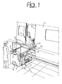
- Figure 1 shows one possible application of the mobile device according to the invention , consisting of boarding/unboarding a disabled person sitting on a wheelchair S relative to the access door P of a railway vehicle body C, within the environment of a railway station.
- the boarding cycle of the disabled person is carried out as follows.
- the assisting operator After loading the wheelchair S onto the platform 12 placed in its lowered position, and after locking in a convention fashion the wheelchair S as well as the disabled person thereon by means of proper safety belts, the assisting operator proceeds to transfer the trolley 1 towards the body C controlling the motor 10 through the check panel 11, and steering of the rear wheel 4 by means of the handlebar 9. The operator then positions the trolley roughly in front of the access door P, stopping in that position. Then acting on the check panel 11, the operator starts the automatic aligning cycle according to which the platform 12 is raised and if necessary transversally shifted until positioning it into precise alignment with the base of the access door P, this position being detected by the optical detecting system 21 - 22. Then the transfer ramp 20 is extracted and advanced until bearing onto the base of the access door P, thus allowing passing through of the wheelchair S towards the inside of the body C. Unloading of the wheelchair S is evidently performed carrying out the above disclosed steps in a reversed way.
- the device can be equally advantageously used in all cases a disabled person on a wheelchair needs to be transferred from a lower backward area to an upper advanced area, and vice-versa.
Abstract
Description
- The present invention is generally related to handling systems for disabled persons sitting on wheelchairs. More particularly, the invention is directed to a mobile device designed to enable transportation of the disabled person towards an access site, for instance the inlet door of a vehicle, and then his or her transfer to and through said access site, and vice-versa. In the case of a vehicle, for example a railway vehicle, the access site is namely consisting of a door opening arranged at a higher level than the railway station platform. Similar conditions are to be founded even in the case of wheel vehicles and of architectural sites wherein only steps and not shute ramps are provided get over even low level differences.
- In all these cases autonomous access of the disabled person on his wheelchair is prevented, and resorting to elevator systems with the aid of assisting personnel is necessarily required.
- Such an elevator system, expressly provided for boarding and unboarding a wheelchair relative to the body of a railway vehicle, is disclosed and illustrated in German Patent Application DE-A-4128076. This system consists of a manually displaceable trolley carrying a horizontal platform designed to bear the wheelchair, and lifting means to vertically displace the platform up to the level of the railway body access door.
- This known device would seem to provide a limited functional efficiency, particularly owing to the fact that correct aligning of the platform with the narrow door opening of a railway vehicle, so as to enable carrying out the wheelchair boarding and unboarding, requires relatively long operations by the disabled person's assistant, which evidently involves uncomfortableness for the disabled person himself or herself. Due to this reason such a known device does not appear having ever been reduced into practice.
- The object of the present invention is to overcome the above drawbacks, and to provide a mobile device for disabled persons of the type set forth in the above, which is effectively suitable for effective employ in all the above disclosed situations, and having nevertheless a relatively simple and economical construction.
- According to the invention, this object is achieved essentially by virtue of the fact that the trolley is motor-driven and is provided with an aligning system to line-up the platform relative to an access site for the wheelchair.
- This aligning system conveniently comprises optical detector means carried by the platform and arranged to co-operate with optical locator means to be associated to said access site.
- According to a further feature of the invention the platform may be displaceable not only vertically but also horizontally in a transverse direction with respect to the trolley, and may additionally include a transfer ramp longitudinally displaceable between a retracted position and an extended position for transferring the wheelchair from the platform to the access site and vice-versa.
- The trolley of the mobile device according to the invention can be motor-driven not only as far as advancement thereof is concerned, but even in connection with lifting and/or transverse displacement of the platform and/or longitudinal displacement of the transfer ramp. In this case the aligning system may conveniently comprise an electronic control unit connected to said optical detector means and to motor-actuators of the trolley to perform positioning, automically and according to a guided aligning cycle, said platform with the related transfer ramp into precise correspondence with the access site for the wheelchair.
- Accordingly the assisting operator shall simply have to drive the trolley until approximatively locate it in front of the access site, and then starting the automatic aligning cycle simply checking that this cycle is correctly completed until transfer of the wheelchair from the platform to the access site, or vice-versa.
- The invention will now be disclosed in detail with reference to the accompanying drawings, purely provided by way of non-limiting example, in which:
- Figure 1 is a diagrammatic perspective view showing a mobile device for disabled persons according to the invention in one possible example of practical application,
- Figure 2 is a diagrammatic lateral elevational view of the device showing the platform in a lowered position and the transfer ramp in a retracted position,
- Figure 3 is a view same as figure 2 showing the platform in a raised position and the transfer ramp in an extended position,
- Figure 4 is a top plan view of figure 2,
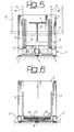
- Figure 5 is a rear elevational and simplified view of figure 3, and
- Figure 6 is a front elevational view of figure 3.
- In the case of the shown embodiment, the mobile device for disabled persons according to the invention is essentially constituted by a tricycle trolley comprising a substantially U-shaped
frame 2 having twofront idle wheels 3 and arear wheel 4 arranged in correspondence of the central area of arear wall 5. Theframe 2 and therear wall 5 are conveniently housed within afairing 6 which, for the sake of simplicity of illustration, is partially omitted in figures 2-6. - The
rear wheel 4 is a steering and motor-driven wheel: to such effect it is carried by afork 7 connected by arod 8 to a driving handlebar, and to which amotor 10 is operatively associated. Themotor 10 may be an electrical or an hydraulic motor, and is operable through a check panel 11 (figure 1) to perform forward and rearward motion as well as braking of the trolley 1. - The
frame 2 of the trolley 1 carries ahorizontal platform 12 designed to bear a wheelchair S. Theplatform 12, which is conveniently provided with a pair ofbanisters 13, is vertically displaceable with respect to the trolley 1 between a completely lowered position, shown in figures 2, 4 and 6, and a raised position shown in figures 1, 3 and 5. To this effect, theplatform 12 is for instance supported by abase plate 14 which is slidably connected in the back tovertical guides 15 of therear wall 5 of theframe 2, and is supported inferiorly by swingingarms 16. Vertical displacement of thebase plate 14 may be operated manually or, more conveniently, in a motor-driven fashion with the aid ofelectrical motors 17. Naturally this arrangement is purely indicative, since the connection between theframe 2 and thebase plate 14 may be performed through pantograph and the like systems, and motorization thereof may be in alternative hydraulic. - The
platform 12 is connected to thebase plate 14 in a horizontally slidable fashion along a transverse direction: accordingly theplatform 12 is coupled to thebase plate 14 by means oftransverse guides 18, and transverse motion thereof can be operated manually and, more conveniently, in a motor-driven fashion by means of an electrical or hydraulic actuator generally designated as 19 in figure 6. - Moreover a
movable transfer ramp 20 is coupled to theplatform 12, which is longitudinally displaceable with respect to theplatform 12 between a retracted position, shown in figures 2, 4 and 6, and an extended or advanced position shown in figures 1, 3 and 5, in which it is projecting on the prolongation of theplatform 12. Displacement of thetransfer ramp 20 can be operated manually or, more conveniently, in a motor-driven fashion with the aid of an electrical or hydraulic motor not shown in the drawings. - According to another peculiar feature of the invention, the trolley 1 is provided with an aligning system designed to centre the
platform 12 with respect to an access site of the wheelchair S carried thereby. This aligning system includes anelectronic check unit 11 operatively connected on one hand to the motor-driven actuators disclosed in the above, intended to displace theplatform 12 vertically and transversely and to shifting longitudinally thetransfer ramp 20, and on the other hand to an optical detecting assembly. This optical detecting assembly may for instance comprise at least one photoelectric passing-through-beam switch including a photo-transmitter 21 secured to the front area of theplatform 12 and a photo-receiver 22 adapted to be applied in immediate proximity of the access site of the wheelchair S. In an alternative embodiment the photoelectric switch may be replaced by a bar-code reader. In any case the optical detecting assembly shall more conveniently comprise at least a pair of sensors designed one to determine the height and the position of theplatform 12 in the transverse direction, and the other to reveal the amount of forwardly displacement of thetransfer ramp 20. - The aligning system disclosed in the above is connected to the
check panel 11 by means of which operation thereof can be started to position automatically and according to a guided aligning cycle theplatform 12 in precise correspondence with the access site for the wheelchair S, and thus transfer thereof towards this access site following advancement of theramp 20. - Naturally the
trolley 2 is equipped with a source of electrical power including batteries, not shown in the drawings, and safety devices of a generally conventional type may further be provided to control the above disclosed motor-driven actuators. - Figure 1 shows one possible application of the mobile device according to the invention , consisting of boarding/unboarding a disabled person sitting on a wheelchair S relative to the access door P of a railway vehicle body C, within the environment of a railway station.
- With reference to this application, the boarding cycle of the disabled person is carried out as follows.
- After loading the wheelchair S onto the
platform 12 placed in its lowered position, and after locking in a convention fashion the wheelchair S as well as the disabled person thereon by means of proper safety belts, the assisting operator proceeds to transfer the trolley 1 towards the body C controlling themotor 10 through thecheck panel 11, and steering of therear wheel 4 by means of thehandlebar 9. The operator then positions the trolley roughly in front of the access door P, stopping in that position. Then acting on thecheck panel 11, the operator starts the automatic aligning cycle according to which theplatform 12 is raised and if necessary transversally shifted until positioning it into precise alignment with the base of the access door P, this position being detected by the optical detecting system 21 - 22. Then thetransfer ramp 20 is extracted and advanced until bearing onto the base of the access door P, thus allowing passing through of the wheelchair S towards the inside of the body C. Unloading of the wheelchair S is evidently performed carrying out the above disclosed steps in a reversed way. - As previously clarified motorization of the
platform 12 and of thetransfer ramp 20 is optional, since operating thereof might also be carried out manually. - Furthermore, while employ of the device according to the invention has been disclosed with specific reference to boarding/unboarding a disabled person relative to a railway vehicle body, it is to be pointed out that the device can be equally advantageously used in all cases a disabled person on a wheelchair needs to be transferred from a lower backward area to an upper advanced area, and vice-versa.
- Naturally the details of construction and the embodiments may be widely varied with respect to what has been disclosed and illustrated without thereby departing from the scope of the present invention such as defined in the appended claims.
Claims (8)
- Mobile device for disabled persons, comprising a trolley (1) carrying a horizontal platform (12) designed to bear a wheelchair (S) and lifting means (15, 16, 17) to vertically displace said platform (12) with respect to trolley (1), characterized in that said trolley (1) is motor-driven (10) and is provided with an aligning system (21, 11) to line-up said platform (12) relative to an access site (P) for the wheelchair (S) .
- Device according to claim 1, characterized in that said platform (12) is further horizontally displaceable in a transverse direction relative to the trolley (1).
- Device according to claim 1 or claim 2, characterized in that said aligning system includes optical detector means (21) carried by the platform (12) and co-operating optical locator means (22) to be associated to said access site (P).
- Device according to any of the preceding claims, characterized in that it comprises a transfer ramp (20) carried by said platform (12) and longitudinally displaceable relative thereto between a retracted position and an extended position.
- Device according to any of the preceding claims, characterized in that said lifting means of the platform (12) comprise motor-driven actuator means (17).
- Device according to claim 2, characterized in that it further comprises motor-driven actuator means (19) operating transverse displacement of said platform (12).
- Device according to claim 4, characterized in that it further comprises motor-driven actuator means operating longitudinal displacement of said transfer ramp (20).
- Device according to the preceding claims, characterized in that said aligning system comprises an electronic control unit (11) connected to said optical detector means (21) and to said motor-driven actuator means (17, 19) to perform positioning, automatically and according to a guided aligning cycle, of said platform (12) in precise correspondence with said access site (P) for said wheelchair (S).
Applications Claiming Priority (2)
| Application Number | Priority Date | Filing Date | Title |
|---|---|---|---|
| ITTO980781 | 1998-09-15 | ||
| IT1998TO000781A IT1305574B1 (en) | 1998-09-15 | 1998-09-15 | DEVICE FOR THE HANDLING OF DISABLED PEOPLE ON WHEELCHAIR, ESPECIALLY FOR EMBARKATION ON A RAILWAY VEHICLE AND SIMILAR. |
Publications (3)
| Publication Number | Publication Date |
|---|---|
| EP0986997A2 true EP0986997A2 (en) | 2000-03-22 |
| EP0986997A3 EP0986997A3 (en) | 2000-11-22 |
| EP0986997B1 EP0986997B1 (en) | 2002-06-26 |
Family
ID=11417039
Family Applications (1)
| Application Number | Title | Priority Date | Filing Date |
|---|---|---|---|
| EP99830521A Expired - Lifetime EP0986997B1 (en) | 1998-09-15 | 1999-08-11 | Mobile device for disabled persons |
Country Status (7)
| Country | Link |
|---|---|
| US (1) | US6419050B1 (en) |
| EP (1) | EP0986997B1 (en) |
| AT (1) | ATE219650T1 (en) |
| CA (1) | CA2280122A1 (en) |
| DE (2) | DE69901924D1 (en) |
| ES (1) | ES2178871T3 (en) |
| IT (1) | IT1305574B1 (en) |
Cited By (2)
| Publication number | Priority date | Publication date | Assignee | Title |
|---|---|---|---|---|
| NL1020532C2 (en) * | 2002-05-03 | 2003-11-04 | Greetje Marjanne Van Der Ploeg | Patient lift comprises frame for support of plate for support of patient and rail for patient to hold, frame having displacement devices for movement of plate and rail between lowermost position and at least one raised position |
| EP1460027A1 (en) * | 2003-03-19 | 2004-09-22 | Azienda Gestione Edifici Comunali | Multifunctional trolley with high mobility |
Families Citing this family (17)
| Publication number | Priority date | Publication date | Assignee | Title |
|---|---|---|---|---|
| US6655905B1 (en) * | 2002-06-04 | 2003-12-02 | Volunteers For Medical Engineering | Linear translation device |
| US20050077111A1 (en) * | 2003-10-14 | 2005-04-14 | The Braun Corporation | Threshold switch apparatus for a mobility access device |
| US7954602B2 (en) * | 2004-11-30 | 2011-06-07 | Joseph Stanislao | Lift apparatus with telescoping platform attachment and method |
| US7926618B2 (en) * | 2004-12-30 | 2011-04-19 | Agm Container Controls, Inc. | Portable wheel chair lift |
| US8146713B2 (en) * | 2006-09-28 | 2012-04-03 | Rosenthal Harry J | Lifting apparatus and method for transporting people and objects |
| US20100059303A1 (en) * | 2006-12-01 | 2010-03-11 | Mp S.R.L. | Self Moving Cart for Invalids, and Method for Managing Said Cart in Business Centres or Other Specific Areas |
| US8079447B2 (en) * | 2007-06-14 | 2011-12-20 | Agm Container Controls, Inc. | Wheel chair lift with protective skirt sensors |
| US7721850B2 (en) * | 2007-06-14 | 2010-05-25 | Agm Container Controls, Inc. | Permanently-installed wheel chair lift with height control |
| IL184390A (en) * | 2007-07-03 | 2014-09-30 | Afikim Electric Vehicles | Mobility scooter |
| US20090300860A1 (en) * | 2008-06-04 | 2009-12-10 | Campbell Patrick L | Portable wheelchair ramp |
| DE102011018618B4 (en) | 2010-04-21 | 2016-03-24 | Technische Universität Kaiserslautern | Easy entry |
| US8973713B2 (en) | 2011-11-03 | 2015-03-10 | Agm Container Controls, Inc. | Height adjustment system for wheelchair lift |
| US8783419B2 (en) | 2011-11-03 | 2014-07-22 | Agm Container Controls, Inc. | Low profile wheelchair lift with direct-acting hydraulic cylinders |
| US9051156B2 (en) | 2011-11-03 | 2015-06-09 | Agm Container Controls, Inc. | Wheelchair lift device with pinned floor struts |
| AT518817B1 (en) * | 2016-06-22 | 2018-07-15 | Bulmor Holding Gmbh | transport vehicle |
| AU2019236731B1 (en) * | 2019-09-26 | 2020-08-20 | The Trustee For Rofraus Trust | Ascending mechanised access ramp (a-mar) |
| EP4000571A1 (en) | 2020-11-18 | 2022-05-25 | Herkules Liftwerk GmbH | Lifter for lifting wheelchairs |
Citations (1)
| Publication number | Priority date | Publication date | Assignee | Title |
|---|---|---|---|---|
| DE4128076A1 (en) | 1991-08-23 | 1993-02-25 | Gotthard Dipl Ing Heide | Device for loading wheelchair into railway carriage - has U=shaped frame on wheels and platform of adjustable height, on frame, with hinged ramps at each end |
Family Cites Families (19)
| Publication number | Priority date | Publication date | Assignee | Title |
|---|---|---|---|---|
| US3598265A (en) * | 1970-01-05 | 1971-08-10 | Stephen F Aaronson | Laterally movable shuttle assembly with an article probe device |
| US3765692A (en) * | 1972-06-07 | 1973-10-16 | Ltv Aerospace Corp | Leveling system |
| SE366009B (en) * | 1972-07-11 | 1974-04-08 | Bygg Och Transportekonomie Ab | |
| US3888463A (en) * | 1973-08-20 | 1975-06-10 | Brien Robert A O | Self-leveling hoist for wheel chairs |
| US4176732A (en) * | 1978-01-12 | 1979-12-04 | Nordskog Robert A | Self-propelled aircraft passenger elevator |
| US4576539A (en) * | 1984-01-17 | 1986-03-18 | Lift-U-Inc. | Wheelchair passenger lift apparatus for transit stations |
| FR2574773B1 (en) * | 1984-12-17 | 1988-02-26 | Inst Textile De France | TROLLEY FOR RECEIVING AND TRANSPORTING A KNITTED PIECE FOR CIRCULAR MATERIALS |
| US4787111A (en) * | 1988-01-11 | 1988-11-29 | Magnum Construction Company, Inc. | Selectively-retractable elevated walkway extension |
| US4971510A (en) * | 1989-01-03 | 1990-11-20 | Houle Handi-Lift Manufacturing Ltd. | Wheelchair passenger device |
| US5553990A (en) * | 1990-04-27 | 1996-09-10 | Kytola, Sr.; David | Hydraulic wheelchair lift |
| US5105915A (en) * | 1990-12-24 | 1992-04-21 | Gary Jerry M | Wheelchair lifting device |
| JP2712901B2 (en) * | 1991-07-26 | 1998-02-16 | 株式会社ダイフク | lift device |
| US5328316A (en) * | 1992-08-04 | 1994-07-12 | Hoffmann Christopher J | Automatic storage and retrieval system having an extendible bin extraction mechanism with pop-up tabs |
| US5322408A (en) * | 1992-09-21 | 1994-06-21 | Handi-Loft, Inc. | Device for raising and lowering an impaired person |
| DE9300793U1 (en) * | 1993-01-21 | 1994-05-26 | Hamburger Hochbahn Ag | Mobile boarding device for wheelchair users, in particular on aircraft |
| US5595470A (en) * | 1994-03-07 | 1997-01-21 | American Airlines, Incorporated | Lift for physically-challenged passengers and method of operation |
| US5499694A (en) * | 1994-08-15 | 1996-03-19 | Stewart & Stevenson Power, Inc. | Self propelled passenger lift vehicle |
| DE4441929C2 (en) * | 1994-11-24 | 2001-09-20 | Geze Gmbh | Boarding device for vehicles, in particular rail vehicles or motor vehicles, in particular for low-floor buses |
| WO1999002443A1 (en) * | 1997-07-14 | 1999-01-21 | Vertical Mobility, Llc | Convertible lift mechanism |
-
1998
- 1998-09-15 IT IT1998TO000781A patent/IT1305574B1/en active
-
1999
- 1999-08-11 DE DE69901924T patent/DE69901924D1/en not_active Expired - Lifetime
- 1999-08-11 ES ES99830521T patent/ES2178871T3/en not_active Expired - Lifetime
- 1999-08-11 AT AT99830521T patent/ATE219650T1/en not_active IP Right Cessation
- 1999-08-11 EP EP99830521A patent/EP0986997B1/en not_active Expired - Lifetime
- 1999-08-12 CA CA002280122A patent/CA2280122A1/en not_active Abandoned
- 1999-09-07 US US09/391,193 patent/US6419050B1/en not_active Expired - Fee Related
- 1999-09-15 DE DE29916236U patent/DE29916236U1/en not_active Expired - Lifetime
Patent Citations (1)
| Publication number | Priority date | Publication date | Assignee | Title |
|---|---|---|---|---|
| DE4128076A1 (en) | 1991-08-23 | 1993-02-25 | Gotthard Dipl Ing Heide | Device for loading wheelchair into railway carriage - has U=shaped frame on wheels and platform of adjustable height, on frame, with hinged ramps at each end |
Cited By (2)
| Publication number | Priority date | Publication date | Assignee | Title |
|---|---|---|---|---|
| NL1020532C2 (en) * | 2002-05-03 | 2003-11-04 | Greetje Marjanne Van Der Ploeg | Patient lift comprises frame for support of plate for support of patient and rail for patient to hold, frame having displacement devices for movement of plate and rail between lowermost position and at least one raised position |
| EP1460027A1 (en) * | 2003-03-19 | 2004-09-22 | Azienda Gestione Edifici Comunali | Multifunctional trolley with high mobility |
Also Published As
| Publication number | Publication date |
|---|---|
| ITTO980781A1 (en) | 2000-03-15 |
| EP0986997B1 (en) | 2002-06-26 |
| CA2280122A1 (en) | 2000-03-15 |
| DE29916236U1 (en) | 1999-12-09 |
| US6419050B1 (en) | 2002-07-16 |
| IT1305574B1 (en) | 2001-05-09 |
| EP0986997A3 (en) | 2000-11-22 |
| ATE219650T1 (en) | 2002-07-15 |
| DE69901924D1 (en) | 2002-08-01 |
| ES2178871T3 (en) | 2003-01-01 |
Similar Documents
| Publication | Publication Date | Title |
|---|---|---|
| US6419050B1 (en) | Mobile device for disabled persons | |
| AU598399B2 (en) | Stair-climbing wheelchair carrier with crawlers | |
| US5205697A (en) | Mobile passenger access lift | |
| US5499694A (en) | Self propelled passenger lift vehicle | |
| CA1060391A (en) | Elecrically powered hand truck with stacker attachment | |
| EP0036293B1 (en) | A motor vehicle having a vehicle entry system for invalids | |
| US8312953B1 (en) | System for storing and retrieving a personal-transportation vehicle | |
| US4551060A (en) | Device for raising various loads, particularly trolleys for handicapped persons, on vehicles | |
| US20080223649A1 (en) | Vehicle for transporting a wheelchair | |
| US4176732A (en) | Self-propelled aircraft passenger elevator | |
| WO2019191899A1 (en) | Automated guided vehicle robot and clamping device thereof | |
| US5050708A (en) | Wheelchair transfer mechanism | |
| US7296960B2 (en) | Coupling system for attachment of a seat to allow securing and/or lifting thereof | |
| US4360307A (en) | Device for vertical and/or horizontal transport of loads into and out of a vehicle or the like | |
| EP0449521B1 (en) | Car parking system and method | |
| GB2071585A (en) | A vehicle entry system for invalids and a wheel chair suitable for use with the entry system | |
| JP3889293B2 (en) | Mechanical parking equipment and vehicle turning device thereof | |
| CN113802903A (en) | Stopping and taking method based on AGV trolley transfer vehicle | |
| US20060239807A1 (en) | Transporter for ride-on power trowel | |
| GB2128560A (en) | Vehicle for disabled person | |
| JP2803919B2 (en) | Transport equipment using self-propelled trolley | |
| KR200151876Y1 (en) | Lifter movement device | |
| JP3010459U (en) | Platform locking device for vehicle lifting device and platform rider head height reduction device | |
| KR20160136903A (en) | Help System And Method for Boarding Of Disabled | |
| KR100654914B1 (en) | Apparatus for horizon maintenance and wheel chair lift comprising the same |
Legal Events
| Date | Code | Title | Description |
|---|---|---|---|
| PUAI | Public reference made under article 153(3) epc to a published international application that has entered the european phase |
Free format text: ORIGINAL CODE: 0009012 |
|
| AK | Designated contracting states |
Kind code of ref document: A2 Designated state(s): AT BE CH CY DE DK ES FI FR GB GR IE IT LI LU MC NL PT SE |
|
| AX | Request for extension of the european patent |
Free format text: AL;LT;LV;MK;RO;SI |
|
| PUAL | Search report despatched |
Free format text: ORIGINAL CODE: 0009013 |
|
| AK | Designated contracting states |
Kind code of ref document: A3 Designated state(s): AT BE CH CY DE DK ES FI FR GB GR IE IT LI LU MC NL PT SE |
|
| AX | Request for extension of the european patent |
Free format text: AL;LT;LV;MK;RO;SI |
|
| 17P | Request for examination filed |
Effective date: 20010329 |
|
| AKX | Designation fees paid |
Free format text: AT BE CH CY DE DK ES FI FR GB GR IE IT LI LU MC NL PT SE |
|
| 17Q | First examination report despatched |
Effective date: 20010711 |
|
| GRAG | Despatch of communication of intention to grant |
Free format text: ORIGINAL CODE: EPIDOS AGRA |
|
| GRAG | Despatch of communication of intention to grant |
Free format text: ORIGINAL CODE: EPIDOS AGRA |
|
| GRAH | Despatch of communication of intention to grant a patent |
Free format text: ORIGINAL CODE: EPIDOS IGRA |
|
| GRAH | Despatch of communication of intention to grant a patent |
Free format text: ORIGINAL CODE: EPIDOS IGRA |
|
| GRAA | (expected) grant |
Free format text: ORIGINAL CODE: 0009210 |
|
| AK | Designated contracting states |
Kind code of ref document: B1 Designated state(s): AT BE CH CY DE DK ES FI FR GB GR IE IT LI LU MC NL PT SE |
|
| PG25 | Lapsed in a contracting state [announced via postgrant information from national office to epo] |
Ref country code: NL Free format text: LAPSE BECAUSE OF FAILURE TO SUBMIT A TRANSLATION OF THE DESCRIPTION OR TO PAY THE FEE WITHIN THE PRESCRIBED TIME-LIMIT Effective date: 20020626 Ref country code: LI Free format text: LAPSE BECAUSE OF FAILURE TO SUBMIT A TRANSLATION OF THE DESCRIPTION OR TO PAY THE FEE WITHIN THE PRESCRIBED TIME-LIMIT Effective date: 20020626 Ref country code: IT Free format text: LAPSE BECAUSE OF FAILURE TO SUBMIT A TRANSLATION OF THE DESCRIPTION OR TO PAY THE FEE WITHIN THE PRE;WARNING: LAPSES OF ITALIAN PATENTS WITH EFFECTIVE DATE BEFORE 2007 MAY HAVE OCCURRED AT ANY TIME BEFORE 2007. THE CORRECT EFFECTIVE DATE MAY BE DIFFERENT FROM THE ONE RECORDED.SCRIBED TIME-LIMIT Effective date: 20020626 Ref country code: GR Free format text: LAPSE BECAUSE OF FAILURE TO SUBMIT A TRANSLATION OF THE DESCRIPTION OR TO PAY THE FEE WITHIN THE PRESCRIBED TIME-LIMIT Effective date: 20020626 Ref country code: FI Free format text: LAPSE BECAUSE OF FAILURE TO SUBMIT A TRANSLATION OF THE DESCRIPTION OR TO PAY THE FEE WITHIN THE PRESCRIBED TIME-LIMIT Effective date: 20020626 Ref country code: CH Free format text: LAPSE BECAUSE OF FAILURE TO SUBMIT A TRANSLATION OF THE DESCRIPTION OR TO PAY THE FEE WITHIN THE PRESCRIBED TIME-LIMIT Effective date: 20020626 Ref country code: BE Free format text: LAPSE BECAUSE OF FAILURE TO SUBMIT A TRANSLATION OF THE DESCRIPTION OR TO PAY THE FEE WITHIN THE PRESCRIBED TIME-LIMIT Effective date: 20020626 Ref country code: AT Free format text: LAPSE BECAUSE OF FAILURE TO SUBMIT A TRANSLATION OF THE DESCRIPTION OR TO PAY THE FEE WITHIN THE PRESCRIBED TIME-LIMIT Effective date: 20020626 |
|
| REF | Corresponds to: |
Ref document number: 219650 Country of ref document: AT Date of ref document: 20020715 Kind code of ref document: T |
|
| REG | Reference to a national code |
Ref country code: GB Ref legal event code: FG4D |
|
| REG | Reference to a national code |
Ref country code: CH Ref legal event code: EP |
|
| REG | Reference to a national code |
Ref country code: IE Ref legal event code: FG4D |
|
| REF | Corresponds to: |
Ref document number: 69901924 Country of ref document: DE Date of ref document: 20020801 |
|
| PG25 | Lapsed in a contracting state [announced via postgrant information from national office to epo] |
Ref country code: LU Free format text: LAPSE BECAUSE OF NON-PAYMENT OF DUE FEES Effective date: 20020811 |
|
| PG25 | Lapsed in a contracting state [announced via postgrant information from national office to epo] |
Ref country code: IE Free format text: LAPSE BECAUSE OF NON-PAYMENT OF DUE FEES Effective date: 20020812 |
|
| RAP2 | Party data changed (patent owner data changed or rights of a patent transferred) |
Owner name: ROLLON S.P.A. |
|
| PG25 | Lapsed in a contracting state [announced via postgrant information from national office to epo] |
Ref country code: CY Free format text: LAPSE BECAUSE OF FAILURE TO SUBMIT A TRANSLATION OF THE DESCRIPTION OR TO PAY THE FEE WITHIN THE PRESCRIBED TIME-LIMIT Effective date: 20020831 |
|
| PG25 | Lapsed in a contracting state [announced via postgrant information from national office to epo] |
Ref country code: SE Free format text: LAPSE BECAUSE OF FAILURE TO SUBMIT A TRANSLATION OF THE DESCRIPTION OR TO PAY THE FEE WITHIN THE PRESCRIBED TIME-LIMIT Effective date: 20020926 Ref country code: PT Free format text: LAPSE BECAUSE OF FAILURE TO SUBMIT A TRANSLATION OF THE DESCRIPTION OR TO PAY THE FEE WITHIN THE PRESCRIBED TIME-LIMIT Effective date: 20020926 Ref country code: DK Free format text: LAPSE BECAUSE OF FAILURE TO SUBMIT A TRANSLATION OF THE DESCRIPTION OR TO PAY THE FEE WITHIN THE PRESCRIBED TIME-LIMIT Effective date: 20020926 |
|
| PG25 | Lapsed in a contracting state [announced via postgrant information from national office to epo] |
Ref country code: DE Free format text: LAPSE BECAUSE OF FAILURE TO SUBMIT A TRANSLATION OF THE DESCRIPTION OR TO PAY THE FEE WITHIN THE PRESCRIBED TIME-LIMIT Effective date: 20020927 |
|
| NLT2 | Nl: modifications (of names), taken from the european patent patent bulletin |
Owner name: ROLLON S.P.A. |
|
| NLV1 | Nl: lapsed or annulled due to failure to fulfill the requirements of art. 29p and 29m of the patents act | ||
| ET | Fr: translation filed | ||
| REG | Reference to a national code |
Ref country code: CH Ref legal event code: PL |
|
| REG | Reference to a national code |
Ref country code: ES Ref legal event code: FG2A Ref document number: 2178871 Country of ref document: ES Kind code of ref document: T3 |
|
| PG25 | Lapsed in a contracting state [announced via postgrant information from national office to epo] |
Ref country code: MC Free format text: LAPSE BECAUSE OF NON-PAYMENT OF DUE FEES Effective date: 20030301 |
|
| PLBE | No opposition filed within time limit |
Free format text: ORIGINAL CODE: 0009261 |
|
| STAA | Information on the status of an ep patent application or granted ep patent |
Free format text: STATUS: NO OPPOSITION FILED WITHIN TIME LIMIT |
|
| REG | Reference to a national code |
Ref country code: IE Ref legal event code: MM4A |
|
| 26N | No opposition filed |
Effective date: 20030327 |
|
| GBPC | Gb: european patent ceased through non-payment of renewal fee |
Effective date: 20060811 |
|
| PG25 | Lapsed in a contracting state [announced via postgrant information from national office to epo] |
Ref country code: GB Free format text: LAPSE BECAUSE OF NON-PAYMENT OF DUE FEES Effective date: 20060811 |
|
| PGFP | Annual fee paid to national office [announced via postgrant information from national office to epo] |
Ref country code: GB Payment date: 20060208 Year of fee payment: 7 |
|
| REG | Reference to a national code |
Ref country code: FR Ref legal event code: PLFP Year of fee payment: 17 |
|
| REG | Reference to a national code |
Ref country code: FR Ref legal event code: PLFP Year of fee payment: 18 |
|
| PGFP | Annual fee paid to national office [announced via postgrant information from national office to epo] |
Ref country code: ES Payment date: 20161003 Year of fee payment: 18 |
|
| PGFP | Annual fee paid to national office [announced via postgrant information from national office to epo] |
Ref country code: FR Payment date: 20160901 Year of fee payment: 18 |
|
| REG | Reference to a national code |
Ref country code: FR Ref legal event code: ST Effective date: 20180430 |
|
| PG25 | Lapsed in a contracting state [announced via postgrant information from national office to epo] |
Ref country code: FR Free format text: LAPSE BECAUSE OF NON-PAYMENT OF DUE FEES Effective date: 20170831 |
|
| REG | Reference to a national code |
Ref country code: ES Ref legal event code: FD2A Effective date: 20181029 |
|
| PG25 | Lapsed in a contracting state [announced via postgrant information from national office to epo] |
Ref country code: ES Free format text: LAPSE BECAUSE OF NON-PAYMENT OF DUE FEES Effective date: 20170812 |