EP0986176A2 - Contactless security switch - Google Patents
Contactless security switch Download PDFInfo
- Publication number
- EP0986176A2 EP0986176A2 EP99116557A EP99116557A EP0986176A2 EP 0986176 A2 EP0986176 A2 EP 0986176A2 EP 99116557 A EP99116557 A EP 99116557A EP 99116557 A EP99116557 A EP 99116557A EP 0986176 A2 EP0986176 A2 EP 0986176A2
- Authority
- EP
- European Patent Office
- Prior art keywords
- safety switch
- switch according
- clock signal
- trigger
- coil
- Prior art date
- Legal status (The legal status is an assumption and is not a legal conclusion. Google has not performed a legal analysis and makes no representation as to the accuracy of the status listed.)
- Granted
Links
Images

Classifications
-
- H—ELECTRICITY
- H03—ELECTRONIC CIRCUITRY
- H03K—PULSE TECHNIQUE
- H03K17/00—Electronic switching or gating, i.e. not by contact-making and –breaking
- H03K17/94—Electronic switching or gating, i.e. not by contact-making and –breaking characterised by the way in which the control signals are generated
- H03K17/965—Switches controlled by moving an element forming part of the switch
- H03K17/97—Switches controlled by moving an element forming part of the switch using a magnetic movable element
- H03K2017/9706—Inductive element
-
- H—ELECTRICITY
- H03—ELECTRONIC CIRCUITRY
- H03K—PULSE TECHNIQUE
- H03K2217/00—Indexing scheme related to electronic switching or gating, i.e. not by contact-making or -breaking covered by H03K17/00
- H03K2217/94—Indexing scheme related to electronic switching or gating, i.e. not by contact-making or -breaking covered by H03K17/00 characterised by the way in which the control signal is generated
- H03K2217/9401—Calibration techniques
- H03K2217/94015—Mechanical, e.g. by displacement of a body, a shielding element, or a magnet, in or out of the sensing area
Definitions
- the invention relates to a non-contact safety switch according to the Preamble of claim 1.
- Safety switches or sensors are used to determine the Closed position of closing parts, such as doors or Locking flaps, opposite lockable parts, such as with corresponding Access openings provided boundary walls, housing walls and the like, and work together with a special actuator for safety reasons, so that their release position cannot be manipulated by simple tools or the like.
- Such safety switches generally comprise a switch unit and a trigger, each of these components on the closable Part and the other is arranged on the closable part.
- Safety switch with mechanical or with magnetic, that is contact-free coupling between the switch unit and trigger is known.
- Non-contact safety switches are based on interconnected Known reed contacts. However, since reed contacts with larger currents or welding capacitive loads is the reliability of such Safety switches are often not sufficient and they also require special ones Evaluation units.
- a primary unit in the form of a switch unit who use a transmit circuit with an oscillator and a transmit coil and a receiver circuit connected to an evaluation unit with at least has a receiver coil and with a secondary unit, a trigger, works together.
- the secondary unit includes a receiver coil and one Trigger coil controlled by the transmitter coil of the primary unit, which in Closing position triggers an alarm signal.
- the primary unit becomes Secondary unit a first frequency and in the opposite direction a second Frequency transmitted.
- such an arrangement does not always offer either the required security standard.
- DE-A-2 033 682 discloses a connection device for electrical devices known with which a battery-powered device with a mains-powered device Signal or energy transmission is brought into mutual contact.
- each includes a permanent magnet in one device Protection tube anchor contact in the other device.
- Protection tube anchor contact in the other device.
- For signal transmission and for Energy transmission is a separate coil with a U-shaped core for each device intended.
- the object of the invention is a non-contact safety switch according to the preamble of claim 1 to create an increased Reliability.
- the switch unit Transmission circuit with a clock signal generator and a transmission coil, one with a Evaluation unit connected to at least one receiver circuit Receiver coil and a Hall sensor responsive to the magnet and the trigger is in the closed position inductively excitable by the transmitter coil the receiver coil exciting trigger coil, wherein in the closed position Evaluation unit after a comparison of the sent and received Clock signals drives an enable path when the Hall sensor via the Magnet is activated, there can be no welding at higher currents or capacitive loads occur, so that the reliability is increased.
- the evaluation unit is preferably in the closed position two signals can be fed, the evaluation unit only controlling the release path if both Signals are present. In this case, a closing part is released compared to a lockable part, the fulfillment of two conditions required.
- the presence of two signals in the evaluation unit is redundant, because the supply of only one signal to the evaluation unit does not result in any loss would mean information regarding the approach of the trigger. Through the redundant design is in relation to the actuation of the safety switch reliability further increased.
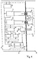
- a safety switch in a first Embodiment a switch unit 1 housed in a housing (for example a power supply connected to a power supply) and one also housed in a housing trigger 2, each on a closable part A or a closing part B are arranged.
- the switch unit 1 is preferably on the closable part A and Trigger 2 arranged on the closing part B.
- the switch unit 1 is powered by an electrical supply source 3 powered and includes a transmission circuit with a clock signal generator 4 for Generation of a clock signal and a transmission coil 5.
- the switch unit 1 further comprises a receiver circuit with a receiver coil 7 and one Hall sensor 9.
- the trigger 2 comprises a magnet 10, which is in the closed position is arranged adjacent to the Hall sensor 9.
- the magnet 10 can be a Be permanent magnet.
- the trigger 2 further comprises a trigger receiver circuit 11 with a trigger coil 12 and a trigger transmission circuit 14 with a coil 15.
- the coils 12 and 15 are arranged so that they in Closed position in each case essentially adjacent to the transmitter coil 5 or Receiver coil 7 lie.
- the trigger receiver circuit 11 is thus over the Trigger coil 12 can be inductively coupled to the transmitter coil 5 of the transmitter circuit, an inductive coupling occurs as soon as transmitter coil 5 and trigger coil 12 are neighboring.
- the trigger send circuit 14 is on the trigger receiver circuit 11 coupled via a modification circuit 17.
- the Hall sensor 9 activated when this is done by the magnet 10 at the location of the Hall sensor 9 generated magnetic field is sufficient to trigger the Hall sensor 9.
- the Hall sensor 9 can be adjusted via a trim resistor 18, so that by Adjusting its switching threshold the distance between switch unit 1 and Trigger 2, in which the Hall sensor 9 triggers, can be set.
- the modification circuit 17 can in particular be a Include frequency divider, which the frequency of the clock signal by one predeterminable factor.
- the trigger transmission circuit 14 thus sends modified clock signal when the trigger receiver circuit 11 has a clock signal received by the broadcasting group.
- the trigger transmission circuit 14 is in turn on the Coil 15 can be inductively coupled to the receiver coil 7 of the receiver circuit, wherein an inductive coupling occurs as soon as the receiver coil 7 and coil 15 are neighboring.
- an inductive coupling occurs as soon as the receiver coil 7 and coil 15 are neighboring.
- the receiver coil 7 thus receives the modified clock signal.
- the Receiver coil 7 is excited with the frequency of the modified clock signal.
- the receiver circuit also contains a bandpass filter 19.
- the bandpass filter 19 is designed so that it is only the one modified by the modifying circuit 17 Passes the clock signal and filters out other external signals. It's about one Amplifier 20 for amplifying the modified clock signal with a pulse shape and Counter stage 21 connected, in which the modified clock signal processed and is added up.
- the clock signal generator 4 is also directly connected to another Pulse shape and count stage 22 connected.
- the pulse shape and counting stage 22 thus receives the unmodified one generated by the clock signal generator 4 Clock signal.
- At the outputs of the pulse shape and counter stages 21, 22 is one common comparator stage 23 connected, its output on a channel a relay stage 24 is performed.
- Another channel of relay stage 24 is with the Hall sensor 9 connected, from Hall sensor 9 an enable signal this channel is supplied when the Hall sensor 9 by approaching the trigger 2 belonging magnet 10 is activated.
- Comparator level 23 evaluates that of the pulse shape and counter stages 21, 22 received counter readings, the Comparator stage 23 by the first incoming signal of counter stage 22 is activated and the pulse shape and counting stages 21, 22 after at least one suitably selected time interval or counter reading.
- the Comparator stage 23 can be designed so that it counts the pulse shape and Counting stages 21, 22 according to suitably chosen, different time intervals or queries, so that the pulse shape and counting stage 21, the modified clock signal with a by a certain factor compared to that of Clock signal generator 4 generated clock signal received lower frequency, first after a time period that is longer by the same factor or by the same time Factor smaller counter reading is queried than the pulse shape and counter stage 22.
- the comparator stage 23 then only outputs an output signal to the relay stage 24 off when the two received counter readings are in a predetermined Stand in relation to each other.
- the counter readings of the pulse form and counter stages 21, 22 can also be queried simultaneously by the relay stage 24, in which case the Comparator stage 23 is designed so that it counts the pulse shape and
- Count stages 21, 22 divided by each other. She only enters then Output signal to the relay stage 24 when the quotient determined Factor of the frequency divider corresponds.
- the pulse shape and counting stages 21, 22 can also be designed so that the different frequency from Clock signal generator 4 generated and modified signal by different Modulation is balanced again.
- the comparator stage 23 then asks Meter readings after the same, suitably selected time periods and only add Match an output signal to relay stage 24.
- the relay stage 24 is connected to an enable path 25.
- the Relay stage 24 is preferably a safety relay stage, which two Safety relay includes.
- the enabling path 25 is switched through via the relay stage 24 only if both channels of relay stage 24 were previously inactive and then a signal is present on both channels of relay stage 24. This sets both ahead that the comparator 23 produces an output signal, as well as that Hall sensor 9 is activated. As a result, the safety switch has one redundant design.
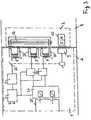
- the transmission circuit comprises Switch unit 1 a switch 26 for closing or interrupting the Transmission circuit that can be switched on via the Hall sensor 9.
- the Trigger 2 to the switch unit 1 is thus the switch 26 via the Hall sensor 9 turned on when the magnet 10 at the location of Hall sensor 9 generated magnetic field is sufficient to trigger the Hall sensor 9.
- the Hall sensor 9 is preferably via a trim resistor 18 adjustable, so that the distance between Switch unit 1 and trigger 2, in which the Hall sensor 9 triggers can be.
- the switch 26 is switched on and thus the broadcasting circuit is closed. Only then is that from Clock signal generator 4 generated clock signal released, whereupon analogous to that in Fig. 1 illustrated embodiment, the transmitter coil 5 due to the inductive Coupling to the trigger receiver circuit 11 induces a voltage in this.
- the trigger 2 and the evaluation unit of the Safety switch constructed exactly as in the first embodiment. 2, however, in the second embodiment, the Clock signal generator 4 does not generate the clock signal continuously, but only at Release by activating the Hall sensor 9 of the pulse shape and counting stage 22 fed. Likewise, the inductive coupling between the transmitter coil 5 of the Transmission circuit and the trigger coil 12 of the trigger receiver circuit 11 only then when transmitter coil 5 and trigger coil 12 are adjacent and the Transmission circuit by activating the Hall sensor 9 by the magnet 10 closed is.
- trigger 2 approaches switch unit 1 and closed transmission circuit is analogous to the first embodiment by the Modifier circuit 17 belonging to trigger 2, modified clock signal of Pulse shape and counter stage 21 supplied.
- the pulse shape and counting stages 21, 22 are analogous to the first embodiment at the common comparator stage 23 connected, the output of which is connected to relay stage 24.
- the one with the Relay stage 24 interconnected release path 25 is only then through the relay mare 24 switched through when the comparator stage 23 released the clock signal and the clock signal modified by the modifying circuit 17 in one receives predetermined frequency ratio. Feeding a shared and a modified signal is redundant because the transmission of only the released signal no loss of information regarding the approximation of the trigger 2 would mean. This embodiment also results thus by the redundant design in relation to the actuation of the Safety switch increased reliability.
- Embodiment 3 is analogous to the second in a third embodiment Embodiment also provided a switch 26 which when the Hall sensor 9 by the magnet 10 that generated by the clock signal generator 4 Clock signal releases.
- the broadcasting circuit comprises analogously to the first two Embodiments of a transmitter coil 5, which here is a magnetizable U-shaped Core 27 has.
- the recipient group comprises two Receiver coils 7, each of which also has a magnetizable U-shaped core 27 and which are each followed by an amplifier stage 20.
- the Outputs of the amplifier stages 20 are each directly with a channel Relay stage 24 connected.
- the trigger 2 includes in addition to the adjacent in the closed position Hall sensor 9 arranged magnets 10 only the trigger coil 12, which in Closed position adjacent to the transmitter coil 5 and the two Receiver coils 7 is arranged.
- the trigger coil 12 also has a U-shaped magnetizable core 27.
Landscapes
- Switches That Are Operated By Magnetic Or Electric Fields (AREA)
- Push-Button Switches (AREA)
- Burglar Alarm Systems (AREA)
- Electronic Switches (AREA)
- Measuring Magnetic Variables (AREA)
Abstract
Description
Die Erfindung betrifft einen berührungslosen Sicherheitsschalter nach dem
Oberbegriff des Anspruchs 1.The invention relates to a non-contact safety switch according to the
Preamble of
Sicherheitsschalter oder -sensoren dienen zum Feststellen der Schließstellung von schließenden Teilen, beispielsweise von Türen oder Verschlußklappen, gegenüber verschließbaren Teilen, etwa mit entsprechenden Zutrittsöffnungen versehene Begrenzungs-, Gehäusewände und dergleichen, und arbeiten aus Sicherheitsgründen mit einem speziellen Betätiger zusammen, so daß ihre Auslösestellung nicht durch einfache Werkzeuge o. dgl. manipulierbar ist. Solche Sicherheitsschalter umfassen im allgemeinen eine Schaltereinheit und einen Auslöser, wobei jeweils eine dieser Komponenten an dem verschließbaren Teil und die andere an dem schließbaren Teil angeordnet ist. Hierbei sind Sicherheitsschalter mit mechanischer oder mit magnetischer, also berührungsfreier Kopplung zwischen Schaltereinheit und Auslöser bekannt.Safety switches or sensors are used to determine the Closed position of closing parts, such as doors or Locking flaps, opposite lockable parts, such as with corresponding Access openings provided boundary walls, housing walls and the like, and work together with a special actuator for safety reasons, so that their release position cannot be manipulated by simple tools or the like. Such safety switches generally comprise a switch unit and a trigger, each of these components on the closable Part and the other is arranged on the closable part. Here are Safety switch with mechanical or with magnetic, that is contact-free coupling between the switch unit and trigger is known.
Im Falle einer mechanischen Kopplung ist eine genaue Ausrichtung mit geringen Toleranzen erforderlich, wodurch eine Justierung erschwert wird. Da mechanische Vorrichtungen nicht berührungsfrei arbeiten, sind sie nur schwierig keimfrei zu halten, was etwa für Anwendungsbereiche im Lebensmittelsektor wichtig ist.In the case of a mechanical coupling, an exact alignment is required small tolerances required, which makes adjustment difficult. There mechanical devices do not work without contact, they are only difficult to keep it germ-free, for example for applications in the food sector important is.
Berührungslose Sicherheitsschalter sind auf der Basis von verschalteten Reedkontakten bekannt. Da Reedkontakte jedoch bei größeren Strömen oder kapazitiven Lasten verschweißen, ist die Zuverlässigkeit solcher Sicherheitsschalter häufig nicht ausreichend, und sie benötigen zudem spezielle Auswerteeinheiten.Non-contact safety switches are based on interconnected Known reed contacts. However, since reed contacts with larger currents or welding capacitive loads is the reliability of such Safety switches are often not sufficient and they also require special ones Evaluation units.
Aus DE-C-4 112 064 ist eine Alarmgeberanordnung mit einer Schaltereinheit bekannt, die einen Sendekreis mit einem Oszillator und einer Sendespule und einen mit einer Diskriminatorschaltung verbundenen Empfängerkreis mit mindestens einer Empfängerspule aufweist. Hierbei wird eine kontinuierliche Energieübertragung auch bei erfolgender Signalübertragung sichergestellt. Allerdings bietet eine derartige Anordnung nicht immer den geforderten Sicherheitsstandard.From DE-C-4 112 064 an alarm transmitter arrangement with a Switch unit known, which has a transmitting circuit with an oscillator and Transmitter coil and one connected to a discriminator circuit Has receiver circuit with at least one receiver coil. Here is a Continuous energy transfer even when signals are transmitted ensured. However, such an arrangement does not always offer that required security standard.
Aus DE-C-3 029 543 ist es auf dem Gebiet der Melde- und Überwachungstechnik bekannt, eine Primäreinheit in Form einer Schaltereinheit die verwenden, die einen Sendekreis mit einem Oszillator und einer Sendespule und einen mit einer Auswerteeinheit verbundenen Empfängerkreis mit mindestens einer Empfängerspule besitzt und mit einer Sekundäreinheit, einem Auslöser, zusammenarbeitet. Die Sekundäreinheit umfaßt eine Empfängerspule und eine von der Sendespule der Primäreinheit gesteuerte Auslöserspule, die in Schließstellung ein Meldesignal auslöst. Dabei wird von der Primäreinheit zur Sekundäreinheit eine erste Frequenz und in umgekehrter Richtung eine zweite Frequenz übertragen. Allerdings bietet auch eine derartige Anordnung nicht immer den geforderten Sicherheitsstandard. From DE-C-3 029 543 it is in the field of reporting and Surveillance technology known, a primary unit in the form of a switch unit who use a transmit circuit with an oscillator and a transmit coil and a receiver circuit connected to an evaluation unit with at least has a receiver coil and with a secondary unit, a trigger, works together. The secondary unit includes a receiver coil and one Trigger coil controlled by the transmitter coil of the primary unit, which in Closing position triggers an alarm signal. The primary unit becomes Secondary unit a first frequency and in the opposite direction a second Frequency transmitted. However, such an arrangement does not always offer either the required security standard.
Aus DE-A-2 033 682 ist eine Anschlußvorrichtung für elektrische Geräte bekannt, mit der ein batteriegespeistes mit einem netzgespeisten Gerät zur Signal- bzw. Energieübertragung gegenseitig in Anlage gebracht wird. Dabei schließt jeweils ein Permanentmagnet im einen Gerät einen Schutzrohrankerkontakt im anderen Gerät. Für die Signalübertragung und für die Energieübertragung ist je Gerät jeweils eine eigne Spule mit U-förmigem Kern vorgesehen.DE-A-2 033 682 discloses a connection device for electrical devices known with which a battery-powered device with a mains-powered device Signal or energy transmission is brought into mutual contact. Here each includes a permanent magnet in one device Protection tube anchor contact in the other device. For signal transmission and for Energy transmission is a separate coil with a U-shaped core for each device intended.
Aus DE-A-4 113 665 ist eine fremdfeldsichere Kontaktanordnung von magnetisch betätigten Schaltelementen zur Überwachung des Schließzustandes von Fenstern und Türen bekannt, wobei ein Dauermagnet an einem Fensterflügel oder einer Türe und mindestens zwei magnetfeldbetätigte Schaltelemente an dem Fenster- bzw. Türrahmen angebracht sind. Hierbei ergibt sich das oben erwähnte Problem des Verschweißens von Kontakten der magnetisch betätigten Schaltelemente.From DE-A-4 113 665 a foreign field-proof contact arrangement of magnetically operated switching elements for monitoring the closed state known from windows and doors, with a permanent magnet on a window sash or a door and at least two magnetic field-actuated switching elements on the Window or door frames are attached. This results in the above Problem of welding contacts of the magnetically operated Switching elements.
Aufgabe der Erfindung ist es, einen berührungslosen Sicherheitsschalter
nach dem Oberbegriff des Anspruchs 1 zu schaffen, der eine erhöhte
Zuverlässigkeit aufweist.The object of the invention is a non-contact safety switch
according to the preamble of
Diese Aufgabe wird entsprechend dem kennzeichnenden Teil des
Anspruchs 1 gelöst.This task is performed according to the characteristic part of the
Dadurch, daß in einem Sicherheitsschalter mit einer Schaltereinheit und einem einen Magneten umfassenden Auslöser die Schaltereinheit einen Sendekreis mit einem Taktsignalgenerator und einer Sendespule, einen mit einer Auswerteeinheit verbundenen Empfängerkreis mit mindestens einer Empfängerspule sowie einen auf den Magneten ansprechenden Hallsensor und der Auslöser eine in Schließstellung von der Sendespule induktiv erregbare und die Empfängerspule erregende Auslöserspule umfaßt, wobei in Schließstellung die Auswerteeinheit nach einem Vergleich der gesendeten und empfangenen Taktsignale einen Freigabepfad ansteuert, wenn der Hallsensor über den Magneten aktiviert ist, kann kein Verschweißen bei größeren Strömen oder kapazitiven Lasten auftreten, so daß die Zuverlässigkeit erhöht wird. The fact that in a safety switch with a switch unit and a trigger comprising a magnet, the switch unit Transmission circuit with a clock signal generator and a transmission coil, one with a Evaluation unit connected to at least one receiver circuit Receiver coil and a Hall sensor responsive to the magnet and the trigger is in the closed position inductively excitable by the transmitter coil the receiver coil exciting trigger coil, wherein in the closed position Evaluation unit after a comparison of the sent and received Clock signals drives an enable path when the Hall sensor via the Magnet is activated, there can be no welding at higher currents or capacitive loads occur, so that the reliability is increased.
Vorzugsweise sind der Auswerteeinheit in Schließstellung zwei Signale zuführbar, wobei die Auswerteeinheit den Freigabepfad nur ansteuert, wenn beide Signale vorliegen. In diesem Fall ist für eine Freigabe eines schließenden Teils gegenüber einem verschließbaren Teil das Erfüllen zweier Bedingungen erforderlich. Das Vorliegen zweier Signale in der Auswerteeinheit ist redundant, weil die Zuführung nur eines Signals zur Auswerteeinheit keinen Verlust an Information hinsichtlich der Annäherung des Auslösers bedeuten würde. Durch die redundante Bauweise wird in Bezug auf die Betätigung des Sicherheitsschalters die Zuverlässigkeit weiter erhöht.The evaluation unit is preferably in the closed position two signals can be fed, the evaluation unit only controlling the release path if both Signals are present. In this case, a closing part is released compared to a lockable part, the fulfillment of two conditions required. The presence of two signals in the evaluation unit is redundant, because the supply of only one signal to the evaluation unit does not result in any loss Would mean information regarding the approach of the trigger. Through the redundant design is in relation to the actuation of the safety switch reliability further increased.
Weitere Ausgestaltungen der Erfindung sind der nachfolgenden Beschreibung und den Unteransprüchen zu entnehmen.Further refinements of the invention are as follows Description and the dependent claims.
Die Erfindung wird nachstehend anhand von in den beigefügten
Abbildungen dargestellten Ausführungsbeispielen näher erläutert.
Gemäß Fig. 1 besitzt ein Sicherheitsschalter in einer ersten
Ausführungsform eine in einem Gehäuse untergebrachte Schaltereinheit 1
(beispielsweise ein an ein Stromnetz angeschlossenes Netzteil) und einen
ebenfalls in einem Gehäuse untergebrachten Auslöser 2, die jeweils an einem
verschließbaren Teil A bzw. einem schließenden Teil B angeordnet sind.
Vorzugsweise ist die Schaltereinheit 1 an dem verschließbaren Teil A und der
Auslöser 2 an dem schließenden Teil B angeordnet.1 has a safety switch in a first
Embodiment a
Die Schaltereinheit 1 wird von einer elektrischen Versorgungsquelle 3
stromversorgt und umfaßt einen Sendekreis mit einem Taktsignalgenerator 4 zum
Erzeugen eines Taktsignals sowie eine Sendespule 5. Die Schaltereinheit 1
umfaßt ferner einen Empfängerkreis mit einer Empfängerspule 7 sowie einen
Hallsensor 9.The
Der Auslöser 2 umfaßt einen Magneten 10, welcher in Schließstellung
benachbart zum Hallsensor 9 angeordnet ist. Der Magnet 10 kann ein
Permanentmagnet sein. Ferner umfaßt der Auslöser 2 einen Auslöserempfängerkreis
11 mit einer Auslöserspule 12 sowie einen Auslösersendekreis 14
mit einer Spule 15. Die Spulen 12 und 15 sind so angeordnet, daß sie in
Schließstellung jeweils im wesentlichen benachbart zur Sendespule 5 bzw. zur
Empfängerspule 7 liegen. Der Auslöserempfängerkreis 11 ist somit über die
Auslöserspule 12 an die Sendespule 5 des Sendekreises induktiv koppelbar,
wobei eine induktive Kopplung eintritt, sobald Sendespule 5 und Auslöserspule 12
benachbart sind. Der Auslösersendekreis 14 ist an den Auslöserempfängerkreis
11 über einen Modifizierkreis 17 gekoppelt.The
Bei Annäherung des Auslösers 2 an die Schaltereinheit 1 wird der
Hallsensor 9 aktiviert, wenn das durch den Magneten 10 am Ort des Hallsensors 9
erzeugte Magnetfeld zur Auslösung des Hallsensors 9 ausreicht. Vorzugsweise ist
der Hallsensor 9 über einen Trimmwiderstand 18 abgleichbar, so daß durch
Justierung seiner Schaltschwelle der Abstand zwischen Schaltereinheit 1 und
Auslöser 2, bei dem der Hallsensor 9 auslöst, festgelegt werden kann. Außerdem
induziert bei Annäherung des Auslösers 2 an die Schaltereinheit 1 die Sendespule
5 infolge der dann einsetzenden induktiven Kopplung zum
Auslöserempfängerkreis 11 in diesem eine Spannung, welche durch den
Modifizierkreis 17 modifiziert wird. Der Modifizierkreis 17 kann insbesondere einen
Frequenzteiler umfassen, welcher die Frequenz des Taktsignals um einen
vorbestimmbaren Faktor herunterteilt. Der Auslösersendekreis 14 sendet somit ein
modifiziertes Taktsignal aus, wenn der Auslöserempfängerkreis 11 ein Taktsignal
vom Sendekreis empfängt. Der Auslösersendekreis 14 ist seinerseits über die
Spule 15 an die Empfängerspule 7 des Empfängerkreises induktiv koppelbar, wobei
eine induktive Kopplung eintritt, sobald Empfängerspule 7 und Spule 15
benachbart sind. Bei Annäherung des Auslösers 2 an die Schaltereinheit 1
empfängt somit die Empfängerspule 7 das modifizierte Taktsignal. Die
Empfängerspule 7 wird mit der Frequenz des modifizierten Taktsignals angeregt.When the
Gegebenenfalls sind Abschirmungen an Sendespule 5 bzw. Empfängerspule
7 und/oder am Auslöserempfänger- bzw. Auslösersendekreis 11, 14
angebracht, so daß eine unerwünschte Kopplung, etwa zwischen Auslösersendekreis
14 und Sendespule 5, vermieden wird. Alternativ kann auch ein
entsprechend kleines Taktsignal gewählt werden, oder es wird ein ausreichend
großer Abstand zwischen Sendespule 5 und Empfängerspule 7 bzw. zwischen
Auslöserempfängerkreis 11 und Auslösersendekreis 14 vorgesehen.If necessary, there are shields on
Der Empfängerkreis enthält auch ein Bandpaßfilter 19. Das Bandpaßfilter
19 ist so ausgelegt, daß es nur das durch den Modifizierkreis 17 modifizierte
Taktsignal durchläßt und sonstige Fremdsignale ausfiltert. Es ist über einen
Verstärker 20 zur Verstärkung des modifizierten Taktsignals mit einer Impulsform- und
Zählstufe 21 verbunden, in der das modifizierte Taktsignal aufbereitet und
aufaddiert wird.The receiver circuit also contains a
Der Taktsignalgenerator 4 ist außerdem direkt mit einer weiteren
Impulsform- und Zählstufe 22 verbunden. Die Impulsform- und Zählstufe 22
empfängt somit das vom Taktsignalgenerator 4 erzeugte, nicht modifizierte
Taktsignal. An die Ausgänge der Impulsform- und Zählstufen 21, 22 ist eine
gemeinsame Vergleicherstufe 23 angeschlossen, deren Ausgang auf einen Kanal
einer Relaisstufe 24 geführt ist. Ein weiterer Kanal der Relaisstufe 24 ist mit dem
Hallsensor 9 verbunden, wobei vom Hallsensor 9 ein Freigabesignal diesem Kanal
zugeführt wird, wenn der Hallsensor 9 durch Annäherung des zum Auslöser 2
gehörenden Magneten 10 aktiviert wird. Die Vergleicherstufe 23 bewertet die von
den Impulsform- und Zählstufen 21, 22 empfangenen Zählerstände, wobei die
Vergleicherstufe 23 durch das erste ankommende Signal der Zählerstufe 22
aktiviert wird und die Impulsform- und Zählstufen 21, 22 nach mindestens einem
geeignet gewählten Zeitintervall oder Zählerstand abfragt.The
Bei Verwendung eines Frequenzteilers als Modifizierkreis 17 kann die
Vergleicherstufe 23 so ausgelegt sein, daß sie die Zählerstände der Impulsform- und
Zählstufen 21, 22 nach geeignet gewählten, unterschiedlichen Zeitintervallen
oder Zählerständen abfragt, so daß die Impulsform- und Zählstufe 21, die das
modifizierte Taktsignal mit einer um einen bestimmten Faktor gegenüber dem vom
Taktsignalgenerator 4 erzeugten Taktsignal niedrigeren Frequenz empfängt, erst
nach einer um denselben Faktor höheren Zeitspanne oder einem um denselben
Faktor kleineren Zählerstand abgefragt wird als die Impulsform- und Zählstufe 22.
Die Vergleicherstufe 23 gibt nur dann ein Ausgangssignal an die Relaisstufe 24
aus, wenn die beiden empfangenen Zählerstände in einem vorbestimmten
Verhältnis zueinander stehen.When using a frequency divider as a
Alternativ können die Zählerstände der Impulsform- und Zählstufen 21, 22
auch gleichzeitig von der Relaisstufe 24 abgefragt werden, wobei dann die
Vergleicherstufe 23 so ausgelegt wird, daß sie die Zählerstände der Impulsform- undAlternatively, the counter readings of the pulse form and counter stages 21, 22
can also be queried simultaneously by the
Zählstufen 21, 22 durcheinander dividiert. Sie gibt nur dann ein
Ausgangssignal an die Relaisstufe 24 aus, wenn der ermittelte Quotient dem
Faktor des Frequenzteilers entspricht. Die Impulsform- und Zählstufen 21, 22
können auch so ausgelegt sein, daß die unterschiedliche Frequenz von vom
Taktsignalgenerator 4 erzeugtem und modifiziertem Signal durch unterschiedliche
Modulation wieder ausgeglichen wird. Die Vergleicherstufe 23 fragt dann die
Zählerstände nach gleichen, geeignet gewählten Zeitspannen ab und gibt nur bei
Übereinstimmung ein Ausgangssignal an die Relaisstufe 24.Count stages 21, 22 divided by each other. She only enters then
Output signal to the
Die Relaisstufe 24 ist mit einem Freigabepfad 25 verschaltet. Die
Relaisstufe 24 ist vorzugsweise eine Sicherheitsrelaisstufe, welche zwei
Sicherheitsrelais umfaßt.The
Eine Durchschaltung des Freigabepfades 25 über die Relaisstufe 24 erfolgt
nur, wenn zuvor beide Kanäle der Relaisstufe 24 inaktiv waren und anschließend
an beiden Kanälen der Relaisstufe 24 jeweils ein Signal vorliegt. Dies setzt sowohl
voraus, daß die Vergleicherstufe 23 ein Ausgangssignal erzeugt, als auch, daß
der Hallsensor 9 aktiviert ist. Infolgedessen weist der Sicherheitsschalter eine
redundante Bauweise auf. The enabling
Gemäß Fig. 2 umfaßt in einer zweiten Ausführungsform der Sendekreis der
Schaltereinheit 1 einen Schalter 26 zum Schließen bzw. Unterbrechen des
Sendekreises, der über den Hallsensor 9 einschaltbar ist. Bei Annäherung des
Auslösers 2 an die Schaltereinheit 1 wird somit der Schalter 26 über den
Hallsensor 9 eingeschaltet, wenn das durch den Magneten 10 am Ort des
Hallsensors 9 erzeugte Magnetfeld zur Auslösung des Hallsensors 9 ausreicht.
Auch hier ist der Hallsensor 9 vorzugsweise über einen Trimmwiderstand 18
abgleichbar, so daß durch Justierung seiner Schaltschwelle der Abstand zwischen
Schaltereinheit 1 und Auslöser 2, bei dem der Hallsensor 9 auslöst, festgelegt
werden kann. Bei Auslösung des Hallsensors 9 wird der Schalter 26 eingeschaltet
und damit der Sendekreis geschlossen. Erst dann wird das vom
Taktsignalgenerator 4 erzeugte Taktsignal freigegeben, woraufhin analog zu der in
Fig. 1 dargestellten Ausführungsform die Sendespule 5 infolge der induktiven
Kopplung zum Auslöserempfängerkreis 11 in diesem eine Spannung induziert.2, in a second embodiment, the transmission circuit comprises
Switch unit 1 a
Im übrigen sind der Auslöser 2 sowie die Auswerteeinheit des
Sicherheitsschalters genauso wie in der ersten Ausführungsform aufgebaut.
Gemäß Fig. 2 wird jedoch in der zweiten Ausführungsform das vom
Taktsignalgenerator 4 erzeugte Taktsignal nicht kontinuierlich, sondern nur bei
Freigabe durch Aktivierung des Hallsensors 9 der Impulsform- und Zählstufe 22
zugeführt. Ebenso tritt die induktive Kopplung zwischen der Sendespule 5 des
Sendekreises und der Auslöserspule 12 des Auslöserempfängerkreises 11 nur
dann ein, wenn Sendespule 5 und Auslöserspule 12 benachbart sind und der
Sendekreis durch Aktivierung des Hallsensors 9 durch den Magneten 10
geschlossen ist. Bei Annäherung des Auslösers 2 an die Schaltereinheit 1 und
geschlossenem Sendekreis wird analog zur ersten Ausführungsform ein durch den
zum Auslöser 2 gehörenden Modifizierkreis 17 modifiziertes Taktsignal der
Impulsform- und Zählstufe 21 zugeführt. Die Impulsform- und Zählstufen 21, 22
sind analog zur ersten Ausführungsform an die gemeinsame Vergleicherstufe 23
angeschlossen, deren Ausgang mit der Relaisstufe 24 verbunden ist. Der mit der
Relaisstufe 24 verschaltete Freigabepfad 25 wird nur dann durch die Relaisstute
24 durchgeschaltet, wenn die Vergleicherstufe 23 das freigegebene Taktsignal
und das durch den Modifizierkreis 17 modifizierte Taktsignal in einem
vorbestimmten Frequenzverhältnis empfängt. Die Zuführung eines freigegebenen
und eines modifizierten Signals ist redundant, weil die Übertragung nur des
freigegebenen Signals keinen Verlust an Information hinsichtlich der Annäherung
des Auslösers 2 bedeuten würde. Auch bei dieser Ausführungsform ergibt sich
somit durch die redundante Bauweise in bezug auf die Betätigung des
Sicherheitsschalters eine erhöhte Zuverlässigkeit.Otherwise, the
Gemäß Fig. 3 ist in einer dritten Ausführungsform analog zur zweiten
Ausführungsform ebenfalls ein Schalter 26 vorgesehen, der bei Auslösung des
Hallsensors 9 durch den Magneten 10 das vom Taktsignalgenerator 4 erzeugte
Taktsignal freigibt. Der Sendekreis umfaßt analog zu den ersten beiden
Ausführungsformen eine Sendespule 5, die hier einen magnetisierbaren U-förmigen
Kern 27 aufweist. Der Empfängerkreis umfaßt jedoch zwei
Empfängerspulen 7, die ebenfalls jeweils einen magnetisierbaren U-förmigen Kern
27 aufweisen und denen jeweils eine Verstärkerstufe 20 nachgeschaltet ist. Die
Ausgänge der Verstärkerstufen 20 sind jeweils direkt mit einem Kanal der
Relaisstufe 24 verbunden.3 is analogous to the second in a third embodiment
Embodiment also provided a
Der Auslöser 2 umfaßt außer dem in Schließstellung benachbart zum
Hallsensor 9 angeordneten Magneten 10 lediglich die Auslöserspule 12, welche in
Schließstellung benachbart zur Sendespule 5 und zu den beiden
Empfängerspulen 7 angeordnet ist. Die Auslöserspule 12 weist ebenfalls einen U-förmigen
magnetisierbaren Kern 27 auf.The
Im Schließzustand tritt somit sowohl zwischen der Sendespule 5 und der
Auslöserspule 12 als auch zwischen der Auslöserspule 12 und den beiden
Empfängerspulen 7 eine induktive Kopplung ein. Bei Freigabe des vom
Taktsignalgenerator 4 erzeugten Taktsignals induziert somit die Sendespule 5 in
der Auslöserspule 12 eine Spannung, die wiederum eine Spannung in den beiden
Empfängerspulen 7 erzeugt. Das von den Empfängerspulen 7 empfangene Signal
wird über die Verstärkerstufe 20 an die beiden Kanäle der Relaisstufe 24
weitergeleitet. Der mit der Relaisstufe 24 verschaltete Freigabepfad 25 wird
analog zu den ersten beiden Ausführungsformen nur dann durchgeschaltet, wenn
an beiden Kanälen der Relaisstufe 24 jeweils ein Signal vorliegt. Die Zuführung
zweier Signale von den beiden Empfängerspulen 7 an die Relaisstufe 24 ist
analog zu den ersten beiden Ausführungsformen redundant, weil die Übertragung
nur eines Signals keinen Verlust an Information hinsichtlich der Annäherung des
Auslösers 2 bedeuten würde.In the closed state thus occurs both between the
Claims (24)
Applications Claiming Priority (3)
| Application Number | Priority Date | Filing Date | Title |
|---|---|---|---|
| DE19840620A DE19840620C1 (en) | 1998-09-05 | 1998-09-05 | Non-contact safety switch |
| DE19840620 | 1998-09-05 | ||
| US09/388,683 US6212052B1 (en) | 1998-09-05 | 1999-09-02 | Contactless safety switch |
Publications (3)
| Publication Number | Publication Date |
|---|---|
| EP0986176A2 true EP0986176A2 (en) | 2000-03-15 |
| EP0986176A3 EP0986176A3 (en) | 2001-08-01 |
| EP0986176B1 EP0986176B1 (en) | 2004-02-25 |
Family
ID=26048665
Family Applications (1)
| Application Number | Title | Priority Date | Filing Date |
|---|---|---|---|
| EP99116557A Expired - Lifetime EP0986176B1 (en) | 1998-09-05 | 1999-08-24 | Contactless security switch |
Country Status (6)
| Country | Link |
|---|---|
| US (1) | US6212052B1 (en) |
| EP (1) | EP0986176B1 (en) |
| JP (1) | JP2000106071A (en) |
| CN (1) | CN1139959C (en) |
| BR (1) | BR9904153A (en) |
| DE (1) | DE19840620C1 (en) |
Cited By (3)
| Publication number | Priority date | Publication date | Assignee | Title |
|---|---|---|---|---|
| WO2018019684A1 (en) * | 2016-07-29 | 2018-02-01 | Phoenix Contact Gmbh & Co.Kg | Method for signaling the position of a safety device, and safety switching system |
| CN108931182A (en) * | 2017-05-26 | 2018-12-04 | 黑拉有限责任两合公司 | sensor for motor vehicle |
| US10989883B2 (en) | 2017-05-03 | 2021-04-27 | Trumpf Schweiz Ag | Connector arrangements and methods of monitoring connector arrangements |
Families Citing this family (34)
| Publication number | Priority date | Publication date | Assignee | Title |
|---|---|---|---|---|
| DE19928641C1 (en) * | 1999-06-23 | 2001-05-03 | Schmersal K A Gmbh & Co | Safety sensor |
| DE19953898C5 (en) * | 1999-11-10 | 2004-07-01 | K.A. Schmersal Gmbh & Co | Access safety device |
| US7086111B2 (en) * | 2001-03-16 | 2006-08-08 | Braun Gmbh | Electric dental cleaning device |
| DE10159395B4 (en) * | 2001-12-04 | 2010-11-11 | Braun Gmbh | Device for cleaning teeth |
| JP4443116B2 (en) * | 2001-03-14 | 2010-03-31 | ブラウン ゲーエムベーハー | Teeth cleaning method and apparatus |
| US6591523B2 (en) | 2001-03-27 | 2003-07-15 | Apple Corporate Technologies, Inc. | Acoustic card |
| US6675511B2 (en) | 2001-04-20 | 2004-01-13 | Apple Corporate Technologies, Inc. | Acoustic card |
| US6501040B2 (en) | 2001-05-18 | 2002-12-31 | Honeywell International Inc. | Dual directional cable actuated emergency stop device |
| US8443476B2 (en) | 2001-12-04 | 2013-05-21 | Braun Gmbh | Dental cleaning device |
| DE10216225A1 (en) | 2002-04-08 | 2003-10-30 | Euchner Gmbh & Co | Electromagnetic locking system of a safety switch |
| DE102004062150A1 (en) * | 2004-12-23 | 2006-07-13 | Braun Gmbh | Interchangeable accessory for a small electrical appliance and method for determining the service life of the accessory |
| DE102007022827A1 (en) * | 2007-05-15 | 2008-11-20 | Braun Gmbh | Toothbrush attachment and method for its production |
| GB0801706D0 (en) * | 2008-01-31 | 2008-03-05 | Eja Ltd | Safety switch |
| JP5177287B2 (en) * | 2009-04-28 | 2013-04-03 | オムロン株式会社 | Proximity switch |
| GB2470775B (en) * | 2009-06-05 | 2015-06-24 | Mechan Controls Ltd | Safety switching device |
| US8699200B2 (en) * | 2010-02-05 | 2014-04-15 | Honeywell International Inc. | Secure non-contact switch |
| US8456792B2 (en) * | 2010-02-05 | 2013-06-04 | Honeywell International Inc. | Secure non-contact switch |
| TWI545895B (en) * | 2010-03-10 | 2016-08-11 | 旺玖科技股份有限公司 | Contact-less switch and its control method |
| CN103068338B (en) | 2010-08-19 | 2015-05-13 | 博朗有限公司 | Method for operating an electric appliance and electric appliance |
| US8928477B2 (en) * | 2010-10-04 | 2015-01-06 | Dr. Hahn Gmbh & Co. Kg | Method and device for contactless transmission of electric energy and/or electric signals between a wall and a wing fastened to said wall |
| DK2550937T3 (en) | 2011-07-25 | 2014-05-19 | Braun Gmbh | MAGNETIC CONNECTION BETWEEN A TOOTH BRUSH AND A BRUSH HEAD |
| WO2013014632A1 (en) | 2011-07-25 | 2013-01-31 | Braun Gmbh | Linear electro-polymer motors and devices having the same |
| EP2550938B1 (en) | 2011-07-25 | 2015-01-14 | Braun GmbH | Oral hygiene device |
| DE102012107717B3 (en) * | 2012-08-22 | 2013-09-12 | Bernstein Ag | Non-contact safety switch has secondary computer which is arranged to execute security check of data received from actuator and passed on to secondary computer, independent of the primary computer |
| DE102012107715B3 (en) * | 2012-08-22 | 2013-09-12 | Bernstein Ag | Contactless safety switch for contactlessly operating with actuator for monitoring whether protective door of machine is opened, has logic gates adapted to generate switching-off signal independent of signal applied at switching outputs |
| DE102012107716B3 (en) * | 2012-08-22 | 2013-09-26 | Bernstein Ag | Magnetic safety switch for non-contact cooperation with actuator, transmits security code in code portions that are smaller than full data block length of security code in sections between actuator and switch |
| WO2014080578A1 (en) * | 2012-11-21 | 2014-05-30 | パナソニック株式会社 | Non-contact switch device |
| EP2973466A4 (en) * | 2013-03-12 | 2016-11-09 | Fire & Security Hardware Pty Ltd | A position monitoring device |
| US8946653B2 (en) * | 2013-03-14 | 2015-02-03 | Teleflex Medical Incorporated | UV-C catheter hub sterilization and data acquisition system |
| CN107000974B (en) * | 2014-11-27 | 2019-05-07 | 三菱电机株式会社 | The position detecting device of elevator |
| EP3458306B1 (en) | 2016-05-18 | 2020-12-16 | Shanghai Yanfeng Jinqiao Automotive Trim Systems Co., Ltd. | Console assembly for vehicle interior |
| US11572723B2 (en) | 2019-02-27 | 2023-02-07 | Shanghai Yanfeng Jinqiao Automotive Triim Systems Co. Ltd. | Vehicle interior component |
| EP3822031A1 (en) * | 2019-11-14 | 2021-05-19 | Hilti Aktiengesellschaft | Method for controlling and regulating a machine tool |
| CN111104121B (en) * | 2019-12-20 | 2023-05-16 | 抖音视界有限公司 | Detection method, detection device, detection equipment and storage medium |
Citations (4)
| Publication number | Priority date | Publication date | Assignee | Title |
|---|---|---|---|---|
| DE2033682A1 (en) * | 1970-07-07 | 1972-01-27 | Budapesti Radiotechnikai Gyar | Connection device for electrical devices |
| DE3029543A1 (en) * | 1980-08-04 | 1982-02-18 | Hermann Dipl.-Ing. 8000 München Zierhut | Non-contact inductive coupling circuit - has primary and secondary stages with band-pass filters for handling two-way transmissions of different frequencies |
| DE4112064A1 (en) * | 1990-04-12 | 1991-10-17 | Hirschmann Richard Gmbh Co | Contactless inductive energy transfer system |
| DE4113665A1 (en) * | 1991-04-26 | 1992-11-05 | Steinecker Elektronik Gmbh | Magnetically activated proximity switch for security alarm system - has reed switching element between reed contact and short circuit loop to suppress interference fields |
Family Cites Families (6)
| Publication number | Priority date | Publication date | Assignee | Title |
|---|---|---|---|---|
| DE3236224C2 (en) * | 1982-09-30 | 1985-03-28 | Werner Turck Gmbh & Co Kg, 5884 Halver | Inductive proximity switch |
| DE3546245C3 (en) * | 1985-12-28 | 1994-11-17 | Link Walter | Non-contact proximity switch |
| DE3616389A1 (en) * | 1986-05-15 | 1987-11-19 | Turck Werner Kg | Non-contact proximity switch |
| AU5420790A (en) * | 1989-04-14 | 1990-11-16 | Eja Engineering Company Limited | Safety switch assembly |
| JP3363341B2 (en) * | 1997-03-26 | 2003-01-08 | 松下電工株式会社 | Non-contact power transmission device |
| JP3247328B2 (en) * | 1997-12-09 | 2002-01-15 | 浩 坂本 | Non-contact power transmission device |
-
1998
- 1998-09-05 DE DE19840620A patent/DE19840620C1/en not_active Expired - Fee Related
-
1999
- 1999-08-24 EP EP99116557A patent/EP0986176B1/en not_active Expired - Lifetime
- 1999-08-31 CN CNB991181891A patent/CN1139959C/en not_active Expired - Fee Related
- 1999-09-02 US US09/388,683 patent/US6212052B1/en not_active Expired - Lifetime
- 1999-09-03 JP JP11250479A patent/JP2000106071A/en active Pending
- 1999-09-03 BR BR9904153-7A patent/BR9904153A/en not_active IP Right Cessation
Patent Citations (4)
| Publication number | Priority date | Publication date | Assignee | Title |
|---|---|---|---|---|
| DE2033682A1 (en) * | 1970-07-07 | 1972-01-27 | Budapesti Radiotechnikai Gyar | Connection device for electrical devices |
| DE3029543A1 (en) * | 1980-08-04 | 1982-02-18 | Hermann Dipl.-Ing. 8000 München Zierhut | Non-contact inductive coupling circuit - has primary and secondary stages with band-pass filters for handling two-way transmissions of different frequencies |
| DE4112064A1 (en) * | 1990-04-12 | 1991-10-17 | Hirschmann Richard Gmbh Co | Contactless inductive energy transfer system |
| DE4113665A1 (en) * | 1991-04-26 | 1992-11-05 | Steinecker Elektronik Gmbh | Magnetically activated proximity switch for security alarm system - has reed switching element between reed contact and short circuit loop to suppress interference fields |
Cited By (4)
| Publication number | Priority date | Publication date | Assignee | Title |
|---|---|---|---|---|
| WO2018019684A1 (en) * | 2016-07-29 | 2018-02-01 | Phoenix Contact Gmbh & Co.Kg | Method for signaling the position of a safety device, and safety switching system |
| US10928003B2 (en) | 2016-07-29 | 2021-02-23 | Phoenix Contact Gmbh & Co. Kg | Method for signaling the position of a safety device, and safety switching system |
| US10989883B2 (en) | 2017-05-03 | 2021-04-27 | Trumpf Schweiz Ag | Connector arrangements and methods of monitoring connector arrangements |
| CN108931182A (en) * | 2017-05-26 | 2018-12-04 | 黑拉有限责任两合公司 | sensor for motor vehicle |
Also Published As
| Publication number | Publication date |
|---|---|
| EP0986176A3 (en) | 2001-08-01 |
| EP0986176B1 (en) | 2004-02-25 |
| JP2000106071A (en) | 2000-04-11 |
| CN1247374A (en) | 2000-03-15 |
| CN1139959C (en) | 2004-02-25 |
| DE19840620C1 (en) | 2000-04-27 |
| BR9904153A (en) | 2000-09-26 |
| US6212052B1 (en) | 2001-04-03 |
Similar Documents
| Publication | Publication Date | Title |
|---|---|---|
| EP0986176B1 (en) | Contactless security switch | |
| EP0968567B1 (en) | Safety switch | |
| DE3881637T2 (en) | Electrical energy transmission device. | |
| EP0527719B1 (en) | Remote control installation | |
| EP0072016B1 (en) | Device for monitoring the clearance between the cutting bar of a cutting device and the cutting elements movable with respect to the bar | |
| EP1479030B1 (en) | Switching device actuated with a transponder | |
| EP1808879A1 (en) | System for contactless assessment of condition | |
| WO1992018732A1 (en) | Device for operating a door locking and/or alarm installation | |
| DE102005009489A1 (en) | Set of electronic components for a position-detection device has a wake-up device for processing a wakening current pulse in a Wiegand coil | |
| DE3149789C1 (en) | Device for inductive identification of an information item | |
| EP3235141B1 (en) | Method and device for transmitting electrical power and/or signals between a wall and a leaf pivotable relative thereto | |
| EP0316872B1 (en) | Alarm transmitter | |
| DE9404382U1 (en) | Furniture drive | |
| DE2557637A1 (en) | Electronic lock with finter ring key - has element contg. electronic operating information moulded in hard insulating material | |
| DE69904428T2 (en) | DEVICE FOR DETECTING THE PRESENCE OF A HUMAN BODY | |
| DE2452732C3 (en) | Device for determining whether a switch provided as a transducer is in the open or closed state | |
| DE102018126651A1 (en) | Tape with data transmission device | |
| WO2009000870A1 (en) | Electronic status detection device | |
| EP0348818A2 (en) | Circuit arrangement for the transmission of at least one variable value from a single vehicle wheel to a central control unit | |
| DE69226803T2 (en) | Position indicator of a movable member | |
| EP1594207B1 (en) | Protection device for AC and DC leakage currents | |
| DE2310881A1 (en) | DEVICE FOR DISPLAYING A PHYSICAL SIZE MEASURED ON A ROTATING WHEEL | |
| EP0602324A1 (en) | Burglary signalling arrangement | |
| DE69923909T2 (en) | Method and device for controlling one or more devices, in particular a roller shutter roller rotatable in two directions | |
| DE4305361A1 (en) | Method for ensuring the exclusive operation of devices and/or systems, in particular conveyor trucks, by authorised personnel |
Legal Events
| Date | Code | Title | Description |
|---|---|---|---|
| PUAI | Public reference made under article 153(3) epc to a published international application that has entered the european phase |
Free format text: ORIGINAL CODE: 0009012 |
|
| AK | Designated contracting states |
Kind code of ref document: A2 Designated state(s): CH DE FR GB IT LI SE |
|
| AX | Request for extension of the european patent |
Free format text: AL;LT;LV;MK;RO;SI |
|
| PUAL | Search report despatched |
Free format text: ORIGINAL CODE: 0009013 |
|
| AK | Designated contracting states |
Kind code of ref document: A3 Designated state(s): AT BE CH CY DE DK ES FI FR GB GR IE IT LI LU MC NL PT SE |
|
| AX | Request for extension of the european patent |
Free format text: AL;LT;LV;MK;RO;SI |
|
| RIC1 | Information provided on ipc code assigned before grant |
Free format text: 7H 03K 17/97 A, 7G 08B 13/08 B, 7G 08B 13/24 B |
|
| 17P | Request for examination filed |
Effective date: 20010906 |
|
| AKX | Designation fees paid |
Free format text: CH DE FR GB IT LI SE |
|
| GRAP | Despatch of communication of intention to grant a patent |
Free format text: ORIGINAL CODE: EPIDOSNIGR1 |
|
| GRAS | Grant fee paid |
Free format text: ORIGINAL CODE: EPIDOSNIGR3 |
|
| GRAA | (expected) grant |
Free format text: ORIGINAL CODE: 0009210 |
|
| AK | Designated contracting states |
Kind code of ref document: B1 Designated state(s): CH DE FR GB IT LI SE |
|
| REG | Reference to a national code |
Ref country code: GB Ref legal event code: FG4D Free format text: NOT ENGLISH |
|
| REG | Reference to a national code |
Ref country code: CH Ref legal event code: EP |
|
| REG | Reference to a national code |
Ref country code: CH Ref legal event code: NV Representative=s name: ICB INGENIEURS CONSEILS EN BREVETS SA |
|
| REF | Corresponds to: |
Ref document number: 59908625 Country of ref document: DE Date of ref document: 20040401 Kind code of ref document: P |
|
| REG | Reference to a national code |
Ref country code: SE Ref legal event code: TRGR |
|
| GBT | Gb: translation of ep patent filed (gb section 77(6)(a)/1977) |
Effective date: 20040520 |
|
| ET | Fr: translation filed | ||
| PLBE | No opposition filed within time limit |
Free format text: ORIGINAL CODE: 0009261 |
|
| STAA | Information on the status of an ep patent application or granted ep patent |
Free format text: STATUS: NO OPPOSITION FILED WITHIN TIME LIMIT |
|
| 26N | No opposition filed |
Effective date: 20041126 |
|
| PGFP | Annual fee paid to national office [announced via postgrant information from national office to epo] |
Ref country code: CH Payment date: 20060815 Year of fee payment: 8 |
|
| PGFP | Annual fee paid to national office [announced via postgrant information from national office to epo] |
Ref country code: FR Payment date: 20060817 Year of fee payment: 8 |
|
| PGFP | Annual fee paid to national office [announced via postgrant information from national office to epo] |
Ref country code: GB Payment date: 20060824 Year of fee payment: 8 |
|
| PGFP | Annual fee paid to national office [announced via postgrant information from national office to epo] |
Ref country code: IT Payment date: 20060831 Year of fee payment: 8 |
|
| PGFP | Annual fee paid to national office [announced via postgrant information from national office to epo] |
Ref country code: SE Payment date: 20060814 Year of fee payment: 8 |
|
| EUG | Se: european patent has lapsed | ||
| REG | Reference to a national code |
Ref country code: CH Ref legal event code: PL |
|
| GBPC | Gb: european patent ceased through non-payment of renewal fee |
Effective date: 20070824 |
|
| PG25 | Lapsed in a contracting state [announced via postgrant information from national office to epo] |
Ref country code: SE Free format text: LAPSE BECAUSE OF NON-PAYMENT OF DUE FEES Effective date: 20070825 Ref country code: LI Free format text: LAPSE BECAUSE OF NON-PAYMENT OF DUE FEES Effective date: 20070831 Ref country code: CH Free format text: LAPSE BECAUSE OF NON-PAYMENT OF DUE FEES Effective date: 20070831 |
|
| REG | Reference to a national code |
Ref country code: FR Ref legal event code: ST Effective date: 20080430 |
|
| PG25 | Lapsed in a contracting state [announced via postgrant information from national office to epo] |
Ref country code: FR Free format text: LAPSE BECAUSE OF NON-PAYMENT OF DUE FEES Effective date: 20070831 |
|
| PG25 | Lapsed in a contracting state [announced via postgrant information from national office to epo] |
Ref country code: GB Free format text: LAPSE BECAUSE OF NON-PAYMENT OF DUE FEES Effective date: 20070824 |
|
| PG25 | Lapsed in a contracting state [announced via postgrant information from national office to epo] |
Ref country code: IT Free format text: LAPSE BECAUSE OF NON-PAYMENT OF DUE FEES Effective date: 20070824 |
|
| PGFP | Annual fee paid to national office [announced via postgrant information from national office to epo] |
Ref country code: DE Payment date: 20091026 Year of fee payment: 11 |
|
| REG | Reference to a national code |
Ref country code: DE Ref legal event code: R119 Ref document number: 59908625 Country of ref document: DE Effective date: 20110301 |
|
| PG25 | Lapsed in a contracting state [announced via postgrant information from national office to epo] |
Ref country code: DE Free format text: LAPSE BECAUSE OF NON-PAYMENT OF DUE FEES Effective date: 20110301 |