EP0985841B1 - High efficiency brake disc with grooves for water draining and for visual wear control - Google Patents
High efficiency brake disc with grooves for water draining and for visual wear control Download PDFInfo
- Publication number
- EP0985841B1 EP0985841B1 EP98830533A EP98830533A EP0985841B1 EP 0985841 B1 EP0985841 B1 EP 0985841B1 EP 98830533 A EP98830533 A EP 98830533A EP 98830533 A EP98830533 A EP 98830533A EP 0985841 B1 EP0985841 B1 EP 0985841B1
- Authority
- EP
- European Patent Office
- Prior art keywords
- braking
- grooves
- brake disc
- brake
- strip
- Prior art date
- Legal status (The legal status is an assumption and is not a legal conclusion. Google has not performed a legal analysis and makes no representation as to the accuracy of the status listed.)
- Expired - Lifetime
Links
Images

Classifications
-
- F—MECHANICAL ENGINEERING; LIGHTING; HEATING; WEAPONS; BLASTING
- F16—ENGINEERING ELEMENTS AND UNITS; GENERAL MEASURES FOR PRODUCING AND MAINTAINING EFFECTIVE FUNCTIONING OF MACHINES OR INSTALLATIONS; THERMAL INSULATION IN GENERAL
- F16D—COUPLINGS FOR TRANSMITTING ROTATION; CLUTCHES; BRAKES
- F16D65/00—Parts or details
- F16D65/02—Braking members; Mounting thereof
- F16D65/12—Discs; Drums for disc brakes
- F16D65/127—Discs; Drums for disc brakes characterised by properties of the disc surface; Discs lined with friction material
-
- F—MECHANICAL ENGINEERING; LIGHTING; HEATING; WEAPONS; BLASTING
- F16—ENGINEERING ELEMENTS AND UNITS; GENERAL MEASURES FOR PRODUCING AND MAINTAINING EFFECTIVE FUNCTIONING OF MACHINES OR INSTALLATIONS; THERMAL INSULATION IN GENERAL
- F16D—COUPLINGS FOR TRANSMITTING ROTATION; CLUTCHES; BRAKES
- F16D69/00—Friction linings; Attachment thereof; Selection of coacting friction substances or surfaces
- F16D2069/004—Profiled friction surfaces, e.g. grooves, dimples
-
- F—MECHANICAL ENGINEERING; LIGHTING; HEATING; WEAPONS; BLASTING
- F16—ENGINEERING ELEMENTS AND UNITS; GENERAL MEASURES FOR PRODUCING AND MAINTAINING EFFECTIVE FUNCTIONING OF MACHINES OR INSTALLATIONS; THERMAL INSULATION IN GENERAL
- F16D—COUPLINGS FOR TRANSMITTING ROTATION; CLUTCHES; BRAKES
- F16D66/00—Arrangements for monitoring working conditions, e.g. wear, temperature
- F16D66/02—Apparatus for indicating wear
Definitions
- the present invention relates to a high braking efficiency and self-draining brake disc with wear visual control.
- the present invention relates to a high braking efficiency and self-draining brake disc with wear visual control especially suitable for use in disc braking devices.
- braking devices are units able to slow or stop a vehicle or, in general, a moving mass, by transforming the absorbed kinetic energy into thermal energy.
- a type of braking device used in motorcars has a disc constituted by a metal brake disc, fixed to the wheel axis, astride of which pliers act that are fixed to the articulated stub axle or the hubbearer of the vehicle and provided with braking gaskets, generally known as "brake pads".
- the brake disc comprises a braking strip, provided with a swept braking surface on both faces, and a bell or hub fixed to the wheel axis.
- the pliers activated by suitable means, push the brake pads against each swept surface of the braking strip.
- the braking action is therefore produced by the friction between the brake pads and the swept surface of the braking strip of the brake disc.
- the braking torque depends therefore on the geometry of the device, in particular on the radial position of the brake pads, the thrust exercised by the activation means and the wear coefficient between the braking surfaces of the brake disc and the brake pads.
- Object of this invention is to obviate the aforementioned drawbacks of the brake discs of the known art.
- object of this invention is to provide a brake disc such as to allow an easy and complete removal of the water veil from its braking surfaces and such as to be perfectly balanced and of easy and economical realisation.
- the present invention allows to achieve these and other objects, which will appear from the following description, by providing at least one and possibly both faces of the brake disc, in correspondence of the braking strip looking towards the brake pad, with circle-arc-shaped radial grooves opened towards the outside and communicating with the throat or connection channel between the brake disc and the bell.
- a high braking efficiency and self-draining brake disc suitable for use in disc-braking devices, comprising a braking strip having two opposing faces, each being provided with a swept braking surface; a bell fixed to the axis of a wheel and a connection throat between said braking strip and said bell, at least one of said opposing faces being provided with radial grooves shaped as an arc of circle, opened towards the outside of said braking strip and communicating with said connection throat, said radial grooves being extended on all the swept braking surface and having a cross-section provided with a central length shaped as a circumference arc and a front and a back rectilinear opposite lengths connecting said central length shaped as a circumference arc with the external surface of the disc, with a common tangent in the passage point, wherein the front rectilinear length, which during the rotation of the brake disk gets in touch first with a braking pad, is inclined to ease the entering of water pushed
- a brake disc having the features of the preamble of claim 1 is known from DE-A-195 12 934.
- the grooves have the same pitch and the radial dimension of each groove is at least equal to, or preferably greater than, that of the braking pads.
- the radial grooves are provided on both opposing faces of the braking strip, have the same pitch and those located on one face are offset of a half-pitch with respect to the grooves located on the opposite face of the same braking strip.
- the grooves communicate with the connection throat in different zones of said ring and alternate on each face. Besides, this arrangement of the grooves allows to have always at least a brake pad covering at least one of said grooves and, at the same time, the grooves are never covered simultaneously by the brake pads.
- the radial grooves have a cross-section constituted by a central length shaped as a circle arc and by two opposite rectilinear lengths connecting said circumference arc with the external surface of the disc, with a common tangent in the passage point.
- the front one with respect to the rotation of the disc, is inclined, while the back one forms an incidence angle with the braking surface of the disc such as to prevent water leakage.
- the rectilinear front length precedes the circumference arc and therefore gets first in touch with the brake pad. Therefore, water is collected in the circumference arc and expelled by centrifugal force.
- the grooves shaped as mentioned above hinder the formation of the water veil when braking on wet grounds, both because they interrupt the continuity of the surfaces in touch and because their opening towards the outside facilitates the removal of water present on the braking surface of the disc.
- the cross-section of the grooves eases the collection of water brought by the relative movement of the brake pads with respect to the brake disc, while the orientation of the channel exercise a water pumping action towards the outside of the disc, so as to obtain a turbine action.
- the particular conformation of the grooves also causes the surface of the brake pads to be constantly restored as, at each passage of the same on a groove, the back length of each grooves gets gradually in touch with the brake pad and restores it active surface.
- said radial grooves act also as wear visual control means.
- the grooves have a very reduced depth, this means that the disc is worn and must be controlled with more frequency, and when the grooves disappear or are just visible, the brake disc has reached its maximum wear limit and must be replaced.
- At least one of said radial grooves has a prefixed depth less than the other ones, so that its disappearance points out the imminent complete wear of the disc.
- the particular arc of circumference shape of radial grooves allows to obtain them easily by means of a circular hollow milling cutter with a shaped tool.
- the brake disc 1 of the present invention comprises a braking strip 2, a bell 3 fixed to the axis of a wheel (not shown), and a connection throat 4 between said braking strip 2 and said bell 3.
- the braking strip 2 has two opposite faces 2' and 2", provided with a swept braking surface on which the brake pads act during the braking.
- Each face 2' and 2" of the braking strip 2 is provided with radial grooves 5, arranged at a same distance from one another, in correspondence of the swept braking surface designed to get in touch with the braking pads.
- the number of grooves 5 is not critical for the purposes of this invention, but generally they are at least 2 and generally 4 to 10 on each face 2', 2" of the braking strip 2.
- Said grooves 5 are opened towards the outside of the braking strip 2 at the free ends and communicate with said connection throat 4 in the part looking towards the inside of the braking disc 1.
- Grooves 5 are arc-of-circle-shaped and their size is such as to connect the connection throat 4 with the outside of the brake disc.
- Grooves 25 of both faces 2', 2" of the braking strip 2 have the same pitch and the grooves of a face are offset by half-pitch with respect to the grooves of the opposite face of the same braking strip.
- each groove 5 has a central part shaped as an arc of circumference 6 and two rectilinear opposite side lengths 7 and 7' connecting said central part shaped as a circumference arc 6 and the external surface of the disc, with a common tangent in the passage point.
- the front rectilinear length 7 which, during the rotation of the brake disc 1, gets first in touch with the braking pad is inclined to facilitate the entering of water pushed by said pad, while the back rectilinear length 7' forms an incidence angle, for instance of about 90°, with the surface of the brake disc 1 such as to prevent water from flowing out.
- the rectilinear front length 7 precedes the circumference arc 6 and therefore gets first in touch with the brake pad. Water is pushed by the brake pad in the central circumference-arc-shaped length 6 of grooves 5.
- the shape of the cross-section 5 is such that the rectilinear front length 7 eases the entering of water, while the rectilinear back length 7', which forms a substantially right angle and a sharp edge with the braking surface of the brake disc 1, prevents the leakage.
- Water expulsion is caused by the formation of a closed-section channel between the central length 6 of groove 5 and the brake pad, opened opened towards the external periphery of the disc.
- the water collected in said channel is therefore pumped towards the outside and then expelled in the same way as happens in a rotary centrifuge.
- grooves 5 allow a visual control of the braking surfaces of the brake disc and have therefore also the function of a visual indicator of the wear of said brake disc.
- the depth of the radial grooves 5 is not greater than the maximum wear level allowed on each face of the brake disc, indicated by the manufacturer. In this way, when the grooves have a very reduced depth, this means that the brake disc is worn and must be controlled more frequently, and when the grooves disappear or are just visible, the brake disc has reached its maximum wear limit and must be replaced.
- One of the radial grooves 5 may have a depth of about 0.1-0.3 mm less than the other ones, so as to act as an indication of the imminent complete wear of the disc.
Landscapes
- Engineering & Computer Science (AREA)
- General Engineering & Computer Science (AREA)
- Mechanical Engineering (AREA)
- Braking Arrangements (AREA)
Description
- The present invention relates to a high braking efficiency and self-draining brake disc with wear visual control.
- More particularly, the present invention relates to a high braking efficiency and self-draining brake disc with wear visual control especially suitable for use in disc braking devices.
- As is known, braking devices are units able to slow or stop a vehicle or, in general, a moving mass, by transforming the absorbed kinetic energy into thermal energy.
- A type of braking device used in motorcars has a disc constituted by a metal brake disc, fixed to the wheel axis, astride of which pliers act that are fixed to the articulated stub axle or the hubbearer of the vehicle and provided with braking gaskets, generally known as "brake pads". The brake disc comprises a braking strip, provided with a swept braking surface on both faces, and a bell or hub fixed to the wheel axis.
- The pliers, activated by suitable means, push the brake pads against each swept surface of the braking strip. The braking action is therefore produced by the friction between the brake pads and the swept surface of the braking strip of the brake disc.
- The braking torque depends therefore on the geometry of the device, in particular on the radial position of the brake pads, the thrust exercised by the activation means and the wear coefficient between the braking surfaces of the brake disc and the brake pads.
- In conditions of coupling between the surfaces of the brake disc and the brake pads transformed by effect of the interposition between these of a water veil due to atmospheric moist conditions, such as fog, frost, rains, etc. on wet grounds, there happens the known undesired phenomena of reduction of the braking torque. In such conditions, in fact, the friction coefficient between the brake pad and the brake disc drops, as, in spite of the suitable protections, the water reaches the brake disc, wedging into the zone of contact with the brake pads, wetting them. One observes therefore a starting decrease in the friction coefficient and, consequently, of the braking torque, due to the simple fact that the contact is wet.
- In order to increase the reliability on wet grounds, it has been proposed to provide the surfaces of the brake disc with grooves either continuous or closed at the end, so as to create structural irregularities on the gasket-metal contact surface. This type of brake disc, functional though it is, does not allow to solve satisfactorily the problem of the wet contact, as grooves, being closed, do not permit to obtain the complete expulsion of water in the brake pad-disc zone.
- To solve the problem of the wet contact, it has been proposed to provide the braking surfaces of the brake disc looking towards the braking pads, with radial grooves, open towards the outside and curved with a progressive curve, whose radius decreases towards the greater diameters of the disc.
- These grooves solve the drawback of the wet contact entirely, as they allow to obtain the complete expulsion of water from the brake pad-disc contact zone, but their profile is complicated and their realisation require specific and complicated tools, and consequently they affect remarkably the cost of the end product.
- Object of this invention is to obviate the aforementioned drawbacks of the brake discs of the known art.
- More particularly, object of this invention is to provide a brake disc such as to allow an easy and complete removal of the water veil from its braking surfaces and such as to be perfectly balanced and of easy and economical realisation.
- From its more general aspect, the present invention allows to achieve these and other objects, which will appear from the following description, by providing at least one and possibly both faces of the brake disc, in correspondence of the braking strip looking towards the brake pad, with circle-arc-shaped radial grooves opened towards the outside and communicating with the throat or connection channel between the brake disc and the bell.
- The subject matter of the present invention is, therefore, a high braking efficiency and self-draining brake disc, suitable for use in disc-braking devices, comprising a braking strip having two opposing faces, each being provided with a swept braking surface; a bell fixed to the axis of a wheel and a connection throat between said braking strip and said bell, at least one of said opposing faces being provided with radial grooves shaped as an arc of circle, opened towards the outside of said braking strip and communicating with said connection throat, said radial grooves being extended on all the swept braking surface and having a cross-section provided with a central length shaped as a circumference arc and a front and a back rectilinear opposite lengths connecting said central length shaped as a circumference arc with the external surface of the disc, with a common tangent in the passage point, wherein the front rectilinear length, which during the rotation of the brake disk gets in touch first with a braking pad, is inclined to ease the entering of water pushed by the pad, and the back rectilinear length forms an incidence angle with the surface of the brake disk of about 90° to prevent water leakage.
- A brake disc having the features of the preamble of claim 1 is known from DE-A-195 12 934.
- Preferably, the grooves have the same pitch and the radial dimension of each groove is at least equal to, or preferably greater than, that of the braking pads.
- According to a preferred embodiment, the radial grooves are provided on both opposing faces of the braking strip, have the same pitch and those located on one face are offset of a half-pitch with respect to the grooves located on the opposite face of the same braking strip.
- In this way, the grooves communicate with the connection throat in different zones of said ring and alternate on each face. Besides, this arrangement of the grooves allows to have always at least a brake pad covering at least one of said grooves and, at the same time, the grooves are never covered simultaneously by the brake pads.
- According to the invention, the radial grooves have a cross-section constituted by a central length shaped as a circle arc and by two opposite rectilinear lengths connecting said circumference arc with the external surface of the disc, with a common tangent in the passage point. Of said rectilinear lengths, the front one, with respect to the rotation of the disc, is inclined, while the back one forms an incidence angle with the braking surface of the disc such as to prevent water leakage.
- In the rotation direction of the disc and the ensuing relative movement between brake pads and disc, the rectilinear front length precedes the circumference arc and therefore gets first in touch with the brake pad. Therefore, water is collected in the circumference arc and expelled by centrifugal force.
- The grooves shaped as mentioned above hinder the formation of the water veil when braking on wet grounds, both because they interrupt the continuity of the surfaces in touch and because their opening towards the outside facilitates the removal of water present on the braking surface of the disc.
- The cross-section of the grooves eases the collection of water brought by the relative movement of the brake pads with respect to the brake disc, while the orientation of the channel exercise a water pumping action towards the outside of the disc, so as to obtain a turbine action.
- The particular conformation of the grooves also causes the surface of the brake pads to be constantly restored as, at each passage of the same on a groove, the back length of each grooves gets gradually in touch with the brake pad and restores it active surface.
- By adjusting the depth of said radial grooves according to a preferred embodiment so that it is not greater than the maximum wear level on each face of the brake disc indicated by the manufacturer, said radial grooves act also as wear visual control means. When, in fact, the grooves have a very reduced depth, this means that the disc is worn and must be controlled with more frequency, and when the grooves disappear or are just visible, the brake disc has reached its maximum wear limit and must be replaced.
- Preferably, at least one of said radial grooves has a prefixed depth less than the other ones, so that its disappearance points out the imminent complete wear of the disc.
- The particular arc of circumference shape of radial grooves allows to obtain them easily by means of a circular hollow milling cutter with a shaped tool.
- The construction and functional characteristics of the brake disc of the present invention will be better understood thanks to the following description wherein reference is made to the attached drawings which show a preferred embodiment, by way of non limiting example, and wherein:
- Figure 1 shows a schematic front view of the brake disc of the present invention;
- Figure 2 shows an enlarged schematic view of a circle-arc-shaped groove, which each face is provided with, in correspondence of the swept braking surface;
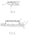
- Figure 3 shows an enlarged schematic view of a section normal to the groove axis of the groove of Figure 2, seen from the Y direction, wherein the cross-section of said groove can be seen; and
- Figure 4 shows a schematic view of a section of the brake disc obtained according to a plane passing along line A-A of Figure 1.
-
- The present description is made with reference to a brake disc of the self-ventilated type, even is the present invention may be applied with the same success to any other type of brake disc, for instance of the solid type.
- With special reference to the figures, the brake disc 1 of the present invention comprises a
braking strip 2, abell 3 fixed to the axis of a wheel (not shown), and a connection throat 4 between saidbraking strip 2 and saidbell 3. - The
braking strip 2 has twoopposite faces 2' and 2", provided with a swept braking surface on which the brake pads act during the braking. - Each
face 2' and 2" of thebraking strip 2 is provided withradial grooves 5, arranged at a same distance from one another, in correspondence of the swept braking surface designed to get in touch with the braking pads. - The number of
grooves 5 is not critical for the purposes of this invention, but generally they are at least 2 and generally 4 to 10 on eachface 2', 2" of thebraking strip 2. - Said
grooves 5 are opened towards the outside of thebraking strip 2 at the free ends and communicate with said connection throat 4 in the part looking towards the inside of the braking disc 1. -
Grooves 5 are arc-of-circle-shaped and their size is such as to connect the connection throat 4 with the outside of the brake disc. - Grooves 25 of both faces 2', 2" of the
braking strip 2 have the same pitch and the grooves of a face are offset by half-pitch with respect to the grooves of the opposite face of the same braking strip. - As can be see in Figure 3, the cross-section of each
groove 5 has a central part shaped as an arc ofcircumference 6 and two rectilinearopposite side lengths 7 and 7' connecting said central part shaped as acircumference arc 6 and the external surface of the disc, with a common tangent in the passage point. - The front
rectilinear length 7 which, during the rotation of the brake disc 1, gets first in touch with the braking pad is inclined to facilitate the entering of water pushed by said pad, while the back rectilinear length 7' forms an incidence angle, for instance of about 90°, with the surface of the brake disc 1 such as to prevent water from flowing out. - In the rotation of the brake disc 1 and the ensuing relative movement between the brake pad and the brake disc, the
rectilinear front length 7 precedes thecircumference arc 6 and therefore gets first in touch with the brake pad. Water is pushed by the brake pad in the central circumference-arc-shaped length 6 ofgrooves 5. The shape of thecross-section 5 is such that therectilinear front length 7 eases the entering of water, while the rectilinear back length 7', which forms a substantially right angle and a sharp edge with the braking surface of the brake disc 1, prevents the leakage. - Water expulsion is caused by the formation of a closed-section channel between the
central length 6 ofgroove 5 and the brake pad, opened opened towards the external periphery of the disc. The water collected in said channel is therefore pumped towards the outside and then expelled in the same way as happens in a rotary centrifuge. - Besides,
grooves 5 allow a visual control of the braking surfaces of the brake disc and have therefore also the function of a visual indicator of the wear of said brake disc. In such case, the depth of theradial grooves 5 is not greater than the maximum wear level allowed on each face of the brake disc, indicated by the manufacturer. In this way, when the grooves have a very reduced depth, this means that the brake disc is worn and must be controlled more frequently, and when the grooves disappear or are just visible, the brake disc has reached its maximum wear limit and must be replaced. One of theradial grooves 5 may have a depth of about 0.1-0.3 mm less than the other ones, so as to act as an indication of the imminent complete wear of the disc. - Even though the present invention has been described with reference to a preferred embodiment of the same, various changes and variants may be made in the brake disc of the present invention, in the light of the above teaching. It is therefore understood that the present invention comprises all the changes and variants that fall within the protection scope of the appended claims.
Claims (8)
- A high braking efficiency and self-draining brake disc (1), suitable for use in disc-braking devices, comprising a braking strip (2) having two opposing faces (2', 2"), each being provided with a swept braking surface; a bell (3) fixed to the axis of a wheel and a connection throat (4) between said braking strip (2) and said bell (3), at least one of said opposing faces (2', 2") being provided with radial grooves (5) shaped as an arc of circle, opened towards the outside of said braking strip (2) and communicating with said throat (4), said radial grooves (5) being extended on all the swept braking surface and having a cross-section provided with a central length shaped as a circumference arc (6) and a front (7) and a back (7') rectilinear opposite lengths connecting said central length shaped as a circumference arc (6) with the external surface of the disc, with a common tangent in the passage point, characterised in that the front rectilinear length (7), which during the rotation of the brake disk (1) gets in touch first with a braking pad, is inclined to ease the entering of water pushed by the pad, and the back rectilinear length (7') forms an incidence angle with the surface of the brake disk (1) of about 90° to prevent water leakage.
- The brake disc according to claim 1, wherein all grooves (5) have the same pitch.
- The brake disc according to claim 1 or 2, wherein grooves (5) are located on both opposite faces (2', 2") of the braking strip (2), and those located on a face are offset by half-pitch with respect to those located on the opposite face of the same braking strip.
- The brake disc according to any of the preceding claims, wherein grooves (5) connect the connection throat (4) with the outside of the brake disc.
- The brake disc according to any of the preceding claims, wherein grooves (5) are at least 2 and preferably comprised between 4 and 10 on each face (2', 2") of the braking strip (2).
- The brake disc according to any of the preceding claims, wherein the radial dimension of each groove (5) is at least equal to, and preferably greater than, that of the braking pads.
- The brake disc according to any of the preceding claims, wherein the depth of grooves (5) is not greater than the maximum wear level allowed on each face of the brake disc.
- The brake disc according to claim 7, wherein one of the grooves (5) has a depth of about 0.1-0.3 mm less than that of the other grooves (5).
Priority Applications (4)
| Application Number | Priority Date | Filing Date | Title |
|---|---|---|---|
| EP98830533A EP0985841B1 (en) | 1998-09-11 | 1998-09-11 | High efficiency brake disc with grooves for water draining and for visual wear control |
| DE69811661T DE69811661T2 (en) | 1998-09-11 | 1998-09-11 | High-performance brake disc with grooves for drainage and optical wear control |
| US09/374,518 US6279698B1 (en) | 1998-09-11 | 1999-08-16 | High efficiency braking and self-draining brake-disk with visual wear control |
| JP11258629A JP2000097266A (en) | 1998-09-11 | 1999-09-13 | Self-ejecting brake disc with high efficiency brake and visibility wear control means |
Applications Claiming Priority (1)
| Application Number | Priority Date | Filing Date | Title |
|---|---|---|---|
| EP98830533A EP0985841B1 (en) | 1998-09-11 | 1998-09-11 | High efficiency brake disc with grooves for water draining and for visual wear control |
Publications (2)
| Publication Number | Publication Date |
|---|---|
| EP0985841A1 EP0985841A1 (en) | 2000-03-15 |
| EP0985841B1 true EP0985841B1 (en) | 2003-02-26 |
Family
ID=8236781
Family Applications (1)
| Application Number | Title | Priority Date | Filing Date |
|---|---|---|---|
| EP98830533A Expired - Lifetime EP0985841B1 (en) | 1998-09-11 | 1998-09-11 | High efficiency brake disc with grooves for water draining and for visual wear control |
Country Status (4)
| Country | Link |
|---|---|
| US (1) | US6279698B1 (en) |
| EP (1) | EP0985841B1 (en) |
| JP (1) | JP2000097266A (en) |
| DE (1) | DE69811661T2 (en) |
Cited By (1)
| Publication number | Priority date | Publication date | Assignee | Title |
|---|---|---|---|---|
| EP0971147B2 (en) † | 1998-07-06 | 2011-07-27 | Industrias Galfer, S.A. | Improved brake disk |
Families Citing this family (23)
| Publication number | Priority date | Publication date | Assignee | Title |
|---|---|---|---|---|
| DE69811661T2 (en) * | 1998-09-11 | 2004-03-18 | Brembo S.P.A., Curno | High-performance brake disc with grooves for drainage and optical wear control |
| US6631791B2 (en) * | 1999-12-15 | 2003-10-14 | Westinghouse Air Brake Co | Brake disc wear indicator |
| AU2000264672A1 (en) * | 2000-07-14 | 2002-01-30 | Freni Brembo S.P.A. | A disc for a disc brake |
| US6457566B1 (en) * | 2001-02-26 | 2002-10-01 | Brake Parts Inc. | Disk brake rotor with visual wear indicator |
| JP2003301872A (en) * | 2002-04-08 | 2003-10-24 | Miki Pulley Co Ltd | Brake mechanism of linear motor device |
| AU2002334401A1 (en) * | 2002-08-30 | 2004-03-19 | Freni Brembo S.P.A. | Disc brake braking band with grooves |
| US6957725B2 (en) * | 2003-02-19 | 2005-10-25 | Dana Corporation | Automotive disc brake |
| US6971490B2 (en) * | 2004-02-04 | 2005-12-06 | Yu-Huan Lin | Brake structure of vehicle |
| US20050252739A1 (en) * | 2004-05-12 | 2005-11-17 | Callahan Fred J | Method of making brake discs and rotors with open slots and brake discs and rotors made therewith |
| US20090084638A1 (en) * | 2004-12-30 | 2009-04-02 | Masterson Steven J | Disc brake pad with visual wear indicator |
| DE102005032638A1 (en) * | 2005-07-13 | 2007-01-25 | Knorr-Bremse Systeme für Nutzfahrzeuge GmbH | Brake disk of disk brake unit, comprises circular groove indicating level of wear and tear |
| US20110048876A1 (en) * | 2006-03-01 | 2011-03-03 | Allen Paul Bujak | Adaptive Profile Brake Arrangement |
| GB0605769D0 (en) * | 2006-03-23 | 2006-05-03 | Qinetiq Ltd | Liquid-cooled disc brakes |
| DE102010037382A1 (en) * | 2010-09-07 | 2012-03-08 | Jürgen Wörner | Brake disc and device for checking the residual thickness of a brake disc |
| US8851245B2 (en) | 2010-12-03 | 2014-10-07 | Brake Parts Inc Llc | Brake rotor |
| WO2013040606A1 (en) * | 2011-09-18 | 2013-03-21 | Withers Graham R | Externally vented aluminum disc brake rotor |
| DE102012106304A1 (en) * | 2012-07-13 | 2014-05-22 | Dr. Ing. H.C. F. Porsche Aktiengesellschaft | brake disc |
| DE102014003985A1 (en) * | 2014-03-19 | 2015-09-24 | Man Truck & Bus Ag | Wear part with a wear indicator and system for wear testing |
| DE102014008844A1 (en) | 2014-06-14 | 2015-12-17 | Daimler Ag | Brake disc for a motor vehicle |
| USD823200S1 (en) | 2016-06-10 | 2018-07-17 | Brake Parts Inc Llc | Vehicle brake rotor |
| DE112017002914T5 (en) | 2016-06-10 | 2019-02-14 | Brake Parts Inc Llc | Brake rotor with optical wear indicator |
| EP3382227B1 (en) * | 2017-03-28 | 2019-11-27 | FCA Italy S.p.A. | Brake disc |
| EP3971440B1 (en) * | 2020-09-21 | 2023-12-27 | Brembo S.p.A. | Braking band of a disc brake disc and disc brake disc |
Family Cites Families (39)
| Publication number | Priority date | Publication date | Assignee | Title |
|---|---|---|---|---|
| DE1425202A1 (en) * | 1961-09-12 | 1968-10-24 | Celestino Benini | Shoe brake, in particular driving eye brake |
| FR1309093A (en) * | 1962-01-03 | 1962-11-09 | Automotive Prod Co Ltd | Brake disc |
| DE2458048A1 (en) * | 1974-12-07 | 1976-06-10 | Porsche Ag | Internally ventilated brake disc for vehicles - has grooves in disc friction surface and matching cooling channels |
| US4286694A (en) * | 1975-12-10 | 1981-09-01 | Goodyear Aerospace Corporation | Grooved carbon brake discs |
| JPS5811949Y2 (en) * | 1977-05-18 | 1983-03-07 | ワタナベエンジニアリング株式会社 | brake disc |
| US4260047A (en) * | 1979-12-03 | 1981-04-07 | General Motors Corporation | Friction disc and method of making same |
| DE2950349A1 (en) * | 1979-12-14 | 1981-06-19 | Daimler-Benz Ag, 7000 Stuttgart | FRICTION COVER FOR A DISC CLUTCH OR BRAKE |
| JPS5837330A (en) * | 1981-08-29 | 1983-03-04 | Suzuki Motor Co Ltd | Disk plate of disk brake |
| JPS5837331A (en) * | 1981-08-31 | 1983-03-04 | Honda Motor Co Ltd | Brake disk |
| JPS59113992A (en) * | 1982-12-21 | 1984-06-30 | Honda Motor Co Ltd | Brake disk groove machining method |
| IN161356B (en) * | 1983-06-11 | 1987-11-14 | Lucas Ind Plc | |
| JPS6037432A (en) * | 1983-08-05 | 1985-02-26 | Nissan Motor Co Ltd | Disk brake |
| JPS60134932U (en) * | 1984-02-20 | 1985-09-07 | トヨタ自動車株式会社 | disc brake disc rotor |
| DE3410127C2 (en) * | 1984-03-20 | 1986-07-31 | Zahnräderfabrik Renk AG, 8900 Augsburg | One-piece brake disc |
| JPS6132836U (en) * | 1984-07-31 | 1986-02-27 | 住友電気工業株式会社 | disk rotor |
| DE3432926A1 (en) * | 1984-09-07 | 1986-03-20 | Selzer Fertigungstechnik Gmbh & Co, 6349 Driedorf | Brake disc, in particular for motor vehicles |
| JPS62297549A (en) * | 1987-06-12 | 1987-12-24 | Honda Motor Co Ltd | brake disc |
| DE3862837D1 (en) * | 1987-07-28 | 1991-06-20 | Lucas Ind Plc | ROTATIONAL PART FOR A VEHICLE BRAKE WITH LIQUID COOLING. |
| EP0364620A1 (en) * | 1988-10-19 | 1990-04-25 | Buderus Kundenguss Gmbh | Massive or ventilated brake discs for motor vehicles |
| DE4002695A1 (en) * | 1990-01-27 | 1991-08-01 | Porsche Ag | BRAKE DISC |
| JPH03255233A (en) * | 1990-03-01 | 1991-11-14 | Endless Project:Kk | Disc rotor |
| EP0665388B1 (en) * | 1992-02-01 | 1998-05-27 | Raybestos Industrie-Produkte GmbH | Friction lining |
| WO1995002130A1 (en) * | 1993-07-07 | 1995-01-19 | Kelsey-Hayes Company | Disc brake rotor |
| US6119828A (en) * | 1994-08-26 | 2000-09-19 | Brake Technologies Pty. Ltd. | Wet disc brake |
| JPH0893809A (en) * | 1994-09-27 | 1996-04-12 | Mitsubishi Heavy Ind Ltd | Disk brake |
| DE19512934C2 (en) * | 1995-04-06 | 2002-04-11 | Continental Teves Ag & Co Ohg | brake disc |
| SE508721C2 (en) * | 1995-05-08 | 1998-11-02 | Volvo Wheel Loaders Ab | Brake slats with built-in acoustic wear warning |
| US5566802A (en) * | 1995-07-17 | 1996-10-22 | Borg-Warner Automotive, Inc. | Continuous slip hydrokinetic torque converter clutch interface with curcuitous groove for cooling and wetting clutch interface zone |
| JPH09144781A (en) * | 1995-09-19 | 1997-06-03 | Aisin Seiki Co Ltd | Disc brake rotor |
| DE29519929U1 (en) * | 1995-12-15 | 1996-02-08 | Knorr-Bremse Systeme für Schienenfahrzeuge GmbH, 80809 München | Rail vehicle brake disc |
| ES2153108T3 (en) * | 1996-05-15 | 2001-02-16 | Continental Teves Ag & Co Ohg | BRAKE DISC. |
| JPH1073136A (en) * | 1996-08-29 | 1998-03-17 | Aisin Seiki Co Ltd | Ventilated disc rotor for disc brake |
| DE29704133U1 (en) * | 1997-03-07 | 1998-08-27 | Unger, Uwe, 68519 Viernheim | Brake disc for vehicle disc brakes |
| IT1295000B1 (en) * | 1997-09-09 | 1999-04-27 | Brembo Engineering S P A | BRAKE DISC WITH HIGH BRAKING AND SELF-BRAKING EFFICIENCY |
| DE19824465A1 (en) * | 1998-05-30 | 1999-12-02 | Volkswagen Ag | Automotive disc brake has surface grooves alternating with rows of cooling holes |
| DE19824971A1 (en) * | 1998-06-04 | 1999-12-23 | Uwe Unger | Brake disk for vehicle |
| EP0985845A1 (en) * | 1998-09-11 | 2000-03-15 | Brembo S.p.A. | Brake disk with visual wear control means |
| DE69811661T2 (en) * | 1998-09-11 | 2004-03-18 | Brembo S.P.A., Curno | High-performance brake disc with grooves for drainage and optical wear control |
| DE69836212D1 (en) * | 1998-09-17 | 2006-11-30 | Freni Brembo Spa | Disc for a disc brake |
-
1998
- 1998-09-11 DE DE69811661T patent/DE69811661T2/en not_active Expired - Lifetime
- 1998-09-11 EP EP98830533A patent/EP0985841B1/en not_active Expired - Lifetime
-
1999
- 1999-08-16 US US09/374,518 patent/US6279698B1/en not_active Expired - Fee Related
- 1999-09-13 JP JP11258629A patent/JP2000097266A/en active Pending
Cited By (1)
| Publication number | Priority date | Publication date | Assignee | Title |
|---|---|---|---|---|
| EP0971147B2 (en) † | 1998-07-06 | 2011-07-27 | Industrias Galfer, S.A. | Improved brake disk |
Also Published As
| Publication number | Publication date |
|---|---|
| JP2000097266A (en) | 2000-04-04 |
| US6279698B1 (en) | 2001-08-28 |
| EP0985841A1 (en) | 2000-03-15 |
| DE69811661D1 (en) | 2003-04-03 |
| DE69811661T2 (en) | 2004-03-18 |
Similar Documents
| Publication | Publication Date | Title |
|---|---|---|
| US6279698B1 (en) | High efficiency braking and self-draining brake-disk with visual wear control | |
| EP2646705B1 (en) | Brake rotor | |
| JP3519114B2 (en) | Friction disc | |
| JPH0262431A (en) | Plate for viscous coupling | |
| US5551537A (en) | Disk brake using a pulled pad with sliding bearing | |
| IT8349577A1 (en) | SLIDING JOINT UNIT IN TRANSMISSION LINES AND RELATED MANUFACTURING METHOD. | |
| US3438464A (en) | Wheel brake disk drive key | |
| SG11202110422TA (en) | Braking system with centrifugal suction in the groove of the lining | |
| US5588508A (en) | Disk brake using a pulled pad with permanent bearing | |
| EP1228322B1 (en) | Brake disc for a vehicle disc brake | |
| EP0902209B1 (en) | High efficiency braking and self-draining brake-disk | |
| EP1677023A2 (en) | Positioning of caliper | |
| KR100322633B1 (en) | Assembly of friction members and springs for disc brakes and disc brakes with these assemblies | |
| EP1656511B1 (en) | Disc to central part interface for disc brakes | |
| US6135248A (en) | Brake disk | |
| EP1697654B1 (en) | Brake disc | |
| EP1301728B1 (en) | A disc for a disc brake | |
| US4460070A (en) | Spot-type brake | |
| US4932509A (en) | Blade for liquid friction couplings | |
| MXPA02005628A (en) | ASSEMBLY PROCEDURE OF A PELTON TYPE TURBINE RODETE. | |
| JPH02189205A (en) | Tire block | |
| JPH0893809A (en) | Disk brake | |
| EP3372859B1 (en) | Energy absorbing constant velocity joint boot assembly | |
| RU2260151C2 (en) | Disc for clasp brake | |
| CA1169778A (en) | Slat for wind energy convertor |
Legal Events
| Date | Code | Title | Description |
|---|---|---|---|
| PUAI | Public reference made under article 153(3) epc to a published international application that has entered the european phase |
Free format text: ORIGINAL CODE: 0009012 |
|
| AK | Designated contracting states |
Kind code of ref document: A1 Designated state(s): DE DK ES FR GB IT |
|
| AX | Request for extension of the european patent |
Free format text: AL;LT;LV;MK;RO;SI |
|
| 17P | Request for examination filed |
Effective date: 20000228 |
|
| AKX | Designation fees paid |
Free format text: DE DK ES FR GB IT |
|
| 17Q | First examination report despatched |
Effective date: 20020206 |
|
| GRAH | Despatch of communication of intention to grant a patent |
Free format text: ORIGINAL CODE: EPIDOS IGRA |
|
| GRAH | Despatch of communication of intention to grant a patent |
Free format text: ORIGINAL CODE: EPIDOS IGRA |
|
| GRAA | (expected) grant |
Free format text: ORIGINAL CODE: 0009210 |
|
| AK | Designated contracting states |
Designated state(s): DE DK ES FR GB IT |
|
| PG25 | Lapsed in a contracting state [announced via postgrant information from national office to epo] |
Ref country code: FR Free format text: LAPSE BECAUSE OF NON-PAYMENT OF DUE FEES Effective date: 20030226 |
|
| REG | Reference to a national code |
Ref country code: GB Ref legal event code: FG4D |
|
| REF | Corresponds to: |
Ref document number: 69811661 Country of ref document: DE Date of ref document: 20030403 Kind code of ref document: P |
|
| PG25 | Lapsed in a contracting state [announced via postgrant information from national office to epo] |
Ref country code: DK Free format text: LAPSE BECAUSE OF FAILURE TO SUBMIT A TRANSLATION OF THE DESCRIPTION OR TO PAY THE FEE WITHIN THE PRESCRIBED TIME-LIMIT Effective date: 20030526 |
|
| PG25 | Lapsed in a contracting state [announced via postgrant information from national office to epo] |
Ref country code: ES Free format text: LAPSE BECAUSE OF FAILURE TO SUBMIT A TRANSLATION OF THE DESCRIPTION OR TO PAY THE FEE WITHIN THE PRESCRIBED TIME-LIMIT Effective date: 20030828 |
|
| PLBE | No opposition filed within time limit |
Free format text: ORIGINAL CODE: 0009261 |
|
| EN | Fr: translation not filed | ||
| 26N | No opposition filed |
Effective date: 20031127 |
|
| PG25 | Lapsed in a contracting state [announced via postgrant information from national office to epo] |
Ref country code: IT Free format text: LAPSE BECAUSE OF NON-PAYMENT OF DUE FEES Effective date: 20050911 |
|
| PGRI | Patent reinstated in contracting state [announced from national office to epo] |
Ref country code: IT Effective date: 20090401 |
|
| PG25 | Lapsed in a contracting state [announced via postgrant information from national office to epo] |
Ref country code: IT Free format text: LAPSE BECAUSE OF NON-PAYMENT OF DUE FEES Effective date: 20110911 |
|
| PGRI | Patent reinstated in contracting state [announced from national office to epo] |
Ref country code: IT Effective date: 20120630 |
|
| PGFP | Annual fee paid to national office [announced via postgrant information from national office to epo] |
Ref country code: DE Payment date: 20130926 Year of fee payment: 16 |
|
| PGFP | Annual fee paid to national office [announced via postgrant information from national office to epo] |
Ref country code: GB Payment date: 20130909 Year of fee payment: 16 |
|
| PGFP | Annual fee paid to national office [announced via postgrant information from national office to epo] |
Ref country code: IT Payment date: 20130930 Year of fee payment: 16 |
|
| REG | Reference to a national code |
Ref country code: DE Ref legal event code: R119 Ref document number: 69811661 Country of ref document: DE |
|
| GBPC | Gb: european patent ceased through non-payment of renewal fee |
Effective date: 20140911 |
|
| PG25 | Lapsed in a contracting state [announced via postgrant information from national office to epo] |
Ref country code: DE Free format text: LAPSE BECAUSE OF NON-PAYMENT OF DUE FEES Effective date: 20150401 Ref country code: GB Free format text: LAPSE BECAUSE OF NON-PAYMENT OF DUE FEES Effective date: 20140911 |
|
| PG25 | Lapsed in a contracting state [announced via postgrant information from national office to epo] |
Ref country code: IT Free format text: LAPSE BECAUSE OF NON-PAYMENT OF DUE FEES Effective date: 20140911 |