EP0985096B1 - Compressor provided with an improved piston - Google Patents
Compressor provided with an improved piston Download PDFInfo
- Publication number
- EP0985096B1 EP0985096B1 EP98924295A EP98924295A EP0985096B1 EP 0985096 B1 EP0985096 B1 EP 0985096B1 EP 98924295 A EP98924295 A EP 98924295A EP 98924295 A EP98924295 A EP 98924295A EP 0985096 B1 EP0985096 B1 EP 0985096B1
- Authority
- EP
- European Patent Office
- Prior art keywords
- piston
- head
- recess
- protrusion
- pistons
- Prior art date
- Legal status (The legal status is an assumption and is not a legal conclusion. Google has not performed a legal analysis and makes no representation as to the accuracy of the status listed.)
- Expired - Lifetime
Links
- 230000000149 penetrating effect Effects 0.000 abstract 1
- 238000000034 method Methods 0.000 description 7
- 230000003247 decreasing effect Effects 0.000 description 1
- 238000006073 displacement reaction Methods 0.000 description 1
- 230000000694 effects Effects 0.000 description 1
- 238000004519 manufacturing process Methods 0.000 description 1
- 238000000926 separation method Methods 0.000 description 1
Images


Classifications
-
- F—MECHANICAL ENGINEERING; LIGHTING; HEATING; WEAPONS; BLASTING
- F04—POSITIVE - DISPLACEMENT MACHINES FOR LIQUIDS; PUMPS FOR LIQUIDS OR ELASTIC FLUIDS
- F04B—POSITIVE-DISPLACEMENT MACHINES FOR LIQUIDS; PUMPS
- F04B39/00—Component parts, details, or accessories, of pumps or pumping systems specially adapted for elastic fluids, not otherwise provided for in, or of interest apart from, groups F04B25/00 - F04B37/00
- F04B39/0005—Component parts, details, or accessories, of pumps or pumping systems specially adapted for elastic fluids, not otherwise provided for in, or of interest apart from, groups F04B25/00 - F04B37/00 adaptations of pistons
Definitions
- the present invention refers to a particular embodiment of an alternating-motion piston reciprocating in a respective cylinder.
- said piston is assumed to work in close association with a compressor for refrigerators, in particular household-type appliances, without this however limiting the scope of the invention solely to such an application or connection.
- This expedient enables the volume of the discharge port that can be occupied by the gas to be temporarily reduced in an artful manner, but to a quite considerable extent, so that the overall compressor efficiency can actually be boosted sensibly, as already mentioned above.
- the grinding operation on the outer cylinder of said compressor pistons is carried out by means of a grinding technique withouta fixed and secured center of rotation; the same process is generally used for producing millions of cylindrical parts such as the cylindrical rollers of roller bearings.
- the grinding process essentially consists in a continuous sequence of said pistons carried by conveying means through a plurality of grinding wheels or similar means being abraded by the action of said plurality of grinding wheels. or similar means.
- the size, orientation and number of said grinding means are such as to enable the pistons conveyed into such a processing step to be sent there in sequence with their axes coinciding with and parallel to the direction of the motion thereof through said plurality of grinding means.
- the grinding process can be noticed to be carried out presently by making use of at least two wheels, ie, an adjustment wheel 1 and an actual grinding wheel 2. Between said wheels, which rotate on parallel axes. a plurality of pistons 3 are caused to pass in a sequence, prelerably carried therethrough on a belt 4 or any other equivalent conveying and support means.
- each piston is spaced from the next one by a separation interval 5 obtained through proper cadencing and separating means 6 that are largely known in the art.
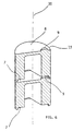
- each piston with a substantially cylindrical recess 7 provided on the side of the piston which is opposed to the head 8 thereof, as this is best illustrated in Figure 4, so as to make it possible, by arranging the pistons against each other and oriented in the same direction, for the protrusion on the head of a piston to freely enter, without any constraint and in any angular position of the same pistons, in said recess of the contiguous piston, thereby obtaining that said protuberances do not interfere with the contiguous pistons, which therefore can maintain the same axis and, at the same time, remain in close contact with each other.
- said recess must have following features: it shall first of all extend inside the body of the piston for a depth that is at least equal to the height of the protrusion 9 from the level of the head 8; furthermore, said recess shall be capable of accomodating the protrusion of the contiguous piston, such as this is illustrated in Figure 6.
- said recess shall be capable of accomodating the protrusion of the contiguous piston, such as this is illustrated in Figure 6.
- Such a link-up can be obtained with a recess 7 that provides, toward the outer cylindrical surface of the piston, a circular edge 12 having no larger thickness than the minimum distance between said protrusion 9 projecting from the head of the piston and the circular edge 13 of the same head.
- such a recess will preferably have a cylindrical shape.
- such a recess may also be given any other appropriate shape, provided that it enables the basic requirement placed on the same recess to be met, ie. the capability thereof to fully accomodate said protrusion thereinto.
Landscapes
- Engineering & Computer Science (AREA)
- Mechanical Engineering (AREA)
- General Engineering & Computer Science (AREA)
- Compressor (AREA)
- Compressors, Vaccum Pumps And Other Relevant Systems (AREA)
Abstract
Description
- The present invention refers to a particular embodiment of an alternating-motion piston reciprocating in a respective cylinder.
- To more effectively exemplify and more clearly illustrate the invention, said piston is assumed to work in close association with a compressor for refrigerators, in particular household-type appliances, without this however limiting the scope of the invention solely to such an application or connection.
- It is a largely known fact that, in view of improving the thermodynamic efficiency of compressors, it is absolutely necessary for the volume of the discharge port, which is not affected by the displacement of the piston, to be as small as possible. The reasons behind such a requirement are well known to those skilled in the art, so that they shall not be dealt with any longer here.
- In view of artificially reducing such a volume, the practice is known in the art, for instance from the disclosure in US 5,149,254, of providing, on the head of the related piston, a protrusion (post 54) that is so arranged and sized as to enable said protrusion to almost fully penetrate into the discharge port when the piston reaches its top dead center, without this of course giving rise to any interference with other parts nearby.
- This expedient enables the volume of the discharge port that can be occupied by the gas to be temporarily reduced in an artful manner, but to a quite considerable extent, so that the overall compressor efficiency can actually be boosted sensibly, as already mentioned above.
- The above solution is certainly simple, reliable, economic and safe; however, in the course of the highly automated production of this kind of pistons a number of practical drawbacks tend to emerge, as described below in greater detail.
- The grinding operation on the outer cylinder of said compressor pistons is carried out by means of a grinding technique withouta fixed and secured center of rotation; the same process is generally used for producing millions of cylindrical parts such as the cylindrical rollers of roller bearings.
- The grinding process essentially consists in a continuous sequence of said pistons carried by conveying means through a plurality of grinding wheels or similar means being abraded by the action of said plurality of grinding wheels. or similar means.
- The size, orientation and number of said grinding means are such as to enable the pistons conveyed into such a processing step to be sent there in sequence with their axes coinciding with and parallel to the direction of the motion thereof through said plurality of grinding means.
- However, if the pistons happen to be arranged in contact with each other, in the sense that the head of one such piston is in contact with the rear edge of the neighbouring piston, then a serious drawback arises in that, owing to the afore mentioned protrusion, said pistons tend to assume a position which is slightly inclined with respect to the direction of motion. The result is that they would come up obliquely in front of or with respect to said grinding means and therefore, would practically prevent the grinding process from being carried out.
- In view of eliminating such a drawback, said pistons are therefore spaced from each other so that the protrusion thereof is prevented from touching any other piston. Such a very simple and effective measure of spacing the pistons from each other, however, has the effect of slowing down and, therefore, decreasing the productivity of the grinding operation, since the pistons must be cadenced into the process at a much lower rate, owing to the need for their forward speed to be maintained unaltered, while the "virtual" length thereof, ie. the length including both the actual length of the piston and the intermediate space that separates it from the subsequent piston in the sequence, is on the contrary increased, as this is best illustrated in the accompanying Figure 1.
- It therefore would be desirable, and is actually a main purpose of the present invention, to provide a technical solution that, when applied to such a compressor piston, does away with the above described drawback in a simple, low-cost and reliable manner. Such an aim shall furthermore be reached through the use of techniques and materials that are simple and readily available on the market, while avoiding to affect the performance capabilities and the overall reliability of the related compressor to any extent.
- According to the present invention such aims are reached in a piston of the kind described below by way of non-limiting example with reference to the accompanying drawings, in which
- Figure 1 is a symbolic representation of a piston grinding plant according to state-of-art technology;
- Figure 2 is a symbolic representation of the same piston grinding plant according to the present invention;
- Figure 3 is a view from the opposite side of the head of a piston according to the present invention;
- Figure 4 is a longitudinal-section view of the same piston shown in Figure 3;
- Figure 5 is a view from the head of the same piston;
- Figure 6 is a sectional view of two pistons according to the present invention, in which the head of one of them is in contact with the bottom portion of the other one.
- With reference to Figure 1 the grinding process can be noticed to be carried out presently by making use of at least two wheels, ie, an
adjustment wheel 1 and anactual grinding wheel 2. Between said wheels, which rotate on parallel axes. a plurality ofpistons 3 are caused to pass in a sequence, prelerably carried therethrough on a belt 4 or any other equivalent conveying and support means. - In view of preventing the protrusion of each piston head from intertering with the contiguous piston as mentioned above, each piston is spaced from the next one by a
separation interval 5 obtained through proper cadencing and separating means 6 that are largely known in the art. - It can be readily appreciated that, if in this case the forward moving rate of the pistons is 700 mm·min, the piston length is 23 mm and the distance of each piston from the next one is 25 mm, then the piston output cadence will amount to
- However, if said pistons could be sent to such a grinding operation without any spacing being provided between them and, therefore, in close contact with each other, as this is symbolically illustrated in Figure 2, then all other conditions remaining unaltered said piston output rate would amount to
- According to the invention, the possibility of feeding the pistons to grinding with the head of each piston in close contact with the bottom of the contiguous piston, wherein each such piston head is provided with the afore described protrusion, is obtained by providing each piston with a substantially
cylindrical recess 7 provided on the side of the piston which is opposed to thehead 8 thereof, as this is best illustrated in Figure 4, so as to make it possible, by arranging the pistons against each other and oriented in the same direction, for the protrusion on the head of a piston to freely enter, without any constraint and in any angular position of the same pistons, in said recess of the contiguous piston, thereby obtaining that said protuberances do not interfere with the contiguous pistons, which therefore can maintain the same axis and, at the same time, remain in close contact with each other. - To such a purpose, said recess must have following features: it shall first of all extend inside the body of the piston for a depth that is at least equal to the height of the
protrusion 9 from the level of thehead 8; furthermore, said recess shall be capable of accomodating the protrusion of the contiguous piston, such as this is illustrated in Figure 6. regardless of the position in which the pistons may find themselves in relation with each other in the direction of rotation with respect to thecommon axis 10. This practically not only enables the pistons to be delivered to the grinding line regardless of the actual angular position or orientation thereof, but also makes it possible for each piston fully free to rotate during grinding and transport, independently of the two pistons that precede and follow it. - Such a link-up can be obtained with a
recess 7 that provides, toward the outer cylindrical surface of the piston, acircular edge 12 having no larger thickness than the minimum distance between saidprotrusion 9 projecting from the head of the piston and thecircular edge 13 of the same head. - Given such constraints, it can be readily appreciated that such a recess will preferably have a cylindrical shape. However, such a recess may also be given any other appropriate shape, provided that it enables the basic requirement placed on the same recess to be met, ie. the capability thereof to fully accomodate said protrusion thereinto.
Claims (3)
- Electric compressor, comprising a cylinder body, a piston provided with a respective head (8), a valve plate arranged between said head and the body of said cylinder and provided with a gas suction port, said head being provided with an excentric protrusion (9) capable of being intermittently inserted in said port, said piston being provided, in the portion thereof which is opposed to the head side, with a recess (7) that is accessible from the outside and is oriented towards the inner volume of said piston, characterized in that said recess extends into the body of said piston down to a depth that is at least equal to the height of said protrusion (9) above the plane of said head.
- Electric compressor according to claim 1, characterized in that said recess has a substantially cylindrical shape having its axis (10) coinciding with the axis of the piston, said recess being further delimited externally by a circular edge (12) that constitutes the terminal portion of the cylindrical surface of the piston opposed to said head, the thickness of said circular edge being not greater than the minimum distance between said protrusion (9) projecting from the naed and the circular edge (13) of the same head.
- Electric compressor according to any of the preceding claims, characterized in that said recess (7) is made integrally with said piston.
Applications Claiming Priority (3)
| Application Number | Priority Date | Filing Date | Title |
|---|---|---|---|
| IT1997PN000024U IT243422Y1 (en) | 1997-05-26 | 1997-05-26 | COMPRESSOR EQUIPPED WITH PERFECTED PISTON |
| ITPN970024U | 1997-05-26 | ||
| PCT/EP1998/002718 WO1998054467A1 (en) | 1997-05-26 | 1998-05-09 | Compressor provided with an improved piston |
Publications (2)
| Publication Number | Publication Date |
|---|---|
| EP0985096A1 EP0985096A1 (en) | 2000-03-15 |
| EP0985096B1 true EP0985096B1 (en) | 2001-12-19 |
Family
ID=11395250
Family Applications (1)
| Application Number | Title | Priority Date | Filing Date |
|---|---|---|---|
| EP98924295A Expired - Lifetime EP0985096B1 (en) | 1997-05-26 | 1998-05-09 | Compressor provided with an improved piston |
Country Status (12)
| Country | Link |
|---|---|
| US (1) | US6164937A (en) |
| EP (1) | EP0985096B1 (en) |
| JP (1) | JP2001526756A (en) |
| CN (1) | CN1116518C (en) |
| AT (1) | ATE211220T1 (en) |
| BR (1) | BR9808358A (en) |
| DE (1) | DE69803066T2 (en) |
| DK (1) | DK0985096T3 (en) |
| ES (1) | ES2170499T3 (en) |
| IT (1) | IT243422Y1 (en) |
| SI (1) | SI0985096T1 (en) |
| WO (1) | WO1998054467A1 (en) |
Families Citing this family (1)
| Publication number | Priority date | Publication date | Assignee | Title |
|---|---|---|---|---|
| US7108184B2 (en) * | 2001-03-30 | 2006-09-19 | Baxter International, Inc. | Coding symbology and a method for printing same |
Family Cites Families (17)
| Publication number | Priority date | Publication date | Assignee | Title |
|---|---|---|---|---|
| GB276541A (en) * | 1926-11-30 | 1927-09-01 | Westinghouse Air Brake Co | Improvements in or relating to fluid compressors |
| US3070122A (en) * | 1960-04-04 | 1962-12-25 | Chrysler Corp | Compressor intake valve |
| US3704079A (en) * | 1970-09-08 | 1972-11-28 | Martin John Berlyn | Air compressors |
| JP2555026B2 (en) * | 1986-05-23 | 1996-11-20 | 株式会社日立製作所 | Variable capacity compressor |
| KR910004933A (en) * | 1989-08-09 | 1991-03-29 | 미다 가쓰시게 | Variable displacement swash plate compressor |
| US5092744A (en) * | 1990-03-14 | 1992-03-03 | Possis Corporation | Intensifier |
| US5149254A (en) | 1991-06-06 | 1992-09-22 | White Consolidated Industries, Inc. | Refrigeration compressor having a contoured piston |
| US5429482A (en) * | 1991-09-11 | 1995-07-04 | Kabushiki Kaisha Toyoda Jidoshokki Seisakusho | Reciprocatory piston type compressor |
| US5266015A (en) * | 1992-02-13 | 1993-11-30 | Tecumseh Products Company | Compressor suction and discharge valve assembly |
| IT1261556B (en) * | 1992-04-27 | 1996-05-23 | Elasis Sistema Ricerca Fiat | RADIAL PISTON PUMP, IN PARTICULAR FOR THE FUEL OF INTERNAL COMBUSTION ENGINES. |
| IT1256214B (en) * | 1992-12-22 | 1995-11-29 | Whirlpool Italia | COMPRESSOR GROUP IN AN EASY ASSEMBLY MOTOR-COMPRESSOR |
| JP3205122B2 (en) * | 1993-05-19 | 2001-09-04 | 株式会社日立製作所 | Hermetic electric compressor |
| US5346373A (en) * | 1993-06-17 | 1994-09-13 | White Consolidated Industries, Inc. | Refrigeration compressor having a spherical discharge valve |
| JPH08170588A (en) * | 1994-12-16 | 1996-07-02 | Toyota Autom Loom Works Ltd | Reciprocating compressor |
| US5655885A (en) * | 1995-03-31 | 1997-08-12 | Chung; Yang Woong | Reciprocating piston pump with modular fluid subassembly |
| US5775886A (en) * | 1996-08-08 | 1998-07-07 | Terwilliger; Gerald L. | Gas compressor with reciprocating piston with valve sheath |
| JPH10169558A (en) * | 1996-12-09 | 1998-06-23 | Toyota Autom Loom Works Ltd | Single-head piston type compressor |
-
1997
- 1997-05-26 IT IT1997PN000024U patent/IT243422Y1/en active
-
1998
- 1998-05-09 US US09/331,371 patent/US6164937A/en not_active Expired - Lifetime
- 1998-05-09 BR BR9808358-9A patent/BR9808358A/en not_active IP Right Cessation
- 1998-05-09 EP EP98924295A patent/EP0985096B1/en not_active Expired - Lifetime
- 1998-05-09 CN CN98801330A patent/CN1116518C/en not_active Expired - Lifetime
- 1998-05-09 DK DK98924295T patent/DK0985096T3/en active
- 1998-05-09 ES ES98924295T patent/ES2170499T3/en not_active Expired - Lifetime
- 1998-05-09 JP JP50015199A patent/JP2001526756A/en active Pending
- 1998-05-09 WO PCT/EP1998/002718 patent/WO1998054467A1/en not_active Ceased
- 1998-05-09 AT AT98924295T patent/ATE211220T1/en not_active IP Right Cessation
- 1998-05-09 SI SI9830127T patent/SI0985096T1/en unknown
- 1998-05-09 DE DE69803066T patent/DE69803066T2/en not_active Expired - Lifetime
Also Published As
| Publication number | Publication date |
|---|---|
| ITPN970024V0 (en) | 1997-05-26 |
| WO1998054467A1 (en) | 1998-12-03 |
| CN1239537A (en) | 1999-12-22 |
| CN1116518C (en) | 2003-07-30 |
| US6164937A (en) | 2000-12-26 |
| DK0985096T3 (en) | 2002-03-25 |
| EP0985096A1 (en) | 2000-03-15 |
| DE69803066D1 (en) | 2002-01-31 |
| JP2001526756A (en) | 2001-12-18 |
| DE69803066T2 (en) | 2002-07-04 |
| SI0985096T1 (en) | 2002-06-30 |
| ES2170499T3 (en) | 2002-08-01 |
| ATE211220T1 (en) | 2002-01-15 |
| IT243422Y1 (en) | 2002-03-04 |
| BR9808358A (en) | 2000-05-23 |
| ITPN970024U1 (en) | 1998-11-26 |
Similar Documents
| Publication | Publication Date | Title |
|---|---|---|
| US7311191B2 (en) | Conveyor system for singulating and orienting | |
| CA2324184A1 (en) | Inline vacuum slug feeder | |
| GB8829331D0 (en) | Reciprocating piston compressor for small refrigerating machines | |
| MY114473A (en) | Refrigerating system | |
| ITRM920256A0 (en) | DELIVERY VALVE FOR RECIPROCATING COMPRESSOR. | |
| IT8619115A0 (en) | RECIPROCATING PISTON COMPRESSOR FOR SMALL REFRIGERATING MACHINES AND ITS ASSEMBLY PROCEDURE. | |
| ES2123020T3 (en) | SLICING MACHINE, IN PARTICULAR FOR TOBACCO BULLETS. | |
| IT8220034A0 (en) | ICE MACHINE WITH FEED PUMP, PARTICULARLY FOR DOMESTIC REFRIGERATORS WITH MULTIPLE STORAGE COMPARTMENTS. | |
| US6164937A (en) | Compressor provided with an improved piston | |
| TW349002B (en) | Apparatus for processing a paste band arranged in layers to form a stack | |
| ES2066276T3 (en) | AN IMPROVED REFRIGERATION CIRCUIT AND METHOD OF DEFROSTING IT. | |
| US3680855A (en) | Pick-off head for sorting machine | |
| GB9922913D0 (en) | Separation unit for grain harvesting | |
| ES8308627A1 (en) | Refrigeration installation with multiple motor compressors. | |
| US3665987A (en) | Shuffle feed positioner | |
| ATE220036T1 (en) | DYNAMIC LOW IMPACT DAMAGE TABLE | |
| AU4296396A (en) | Device to separate flat objects conveyed in stacks | |
| MXPA99003964A (en) | Compressor provided with an improved piston | |
| MXPA04002100A (en) | Arrangement for directing the defrost water in refrigerators. | |
| FR2650655B1 (en) | REFRIGERATION MACHINE, ESPECIALLY HOUSEHOLD REFRIGERATOR | |
| CN108098350A (en) | A kind of clamping device in slot wedge production | |
| ATE332443T1 (en) | PROCESSING SCREW PUMP | |
| PL346397A1 (en) | Evaporator plate | |
| WO2015127997A1 (en) | Hermetic reciprocating mini compressor with reduced size | |
| SU945021A1 (en) | Distribution apparatus |
Legal Events
| Date | Code | Title | Description |
|---|---|---|---|
| PUAI | Public reference made under article 153(3) epc to a published international application that has entered the european phase |
Free format text: ORIGINAL CODE: 0009012 |
|
| 17P | Request for examination filed |
Effective date: 19990312 |
|
| AK | Designated contracting states |
Kind code of ref document: A1 Designated state(s): AT DE DK ES FR GB IT |
|
| AX | Request for extension of the european patent |
Free format text: SI PAYMENT 19990312 |
|
| GRAG | Despatch of communication of intention to grant |
Free format text: ORIGINAL CODE: EPIDOS AGRA |
|
| GRAG | Despatch of communication of intention to grant |
Free format text: ORIGINAL CODE: EPIDOS AGRA |
|
| GRAH | Despatch of communication of intention to grant a patent |
Free format text: ORIGINAL CODE: EPIDOS IGRA |
|
| 17Q | First examination report despatched |
Effective date: 20010522 |
|
| ITF | It: translation for a ep patent filed | ||
| GRAH | Despatch of communication of intention to grant a patent |
Free format text: ORIGINAL CODE: EPIDOS IGRA |
|
| RAP1 | Party data changed (applicant data changed or rights of an application transferred) |
Owner name: ZANUSSI ELETTROMECCANICA S.P.A. |
|
| GRAA | (expected) grant |
Free format text: ORIGINAL CODE: 0009210 |
|
| AK | Designated contracting states |
Kind code of ref document: B1 Designated state(s): AT DE DK ES FR GB IT |
|
| AX | Request for extension of the european patent |
Free format text: SI PAYMENT 19990312 |
|
| REF | Corresponds to: |
Ref document number: 211220 Country of ref document: AT Date of ref document: 20020115 Kind code of ref document: T |
|
| REG | Reference to a national code |
Ref country code: GB Ref legal event code: IF02 |
|
| REF | Corresponds to: |
Ref document number: 69803066 Country of ref document: DE Date of ref document: 20020131 |
|
| REG | Reference to a national code |
Ref country code: DK Ref legal event code: T3 |
|
| ET | Fr: translation filed | ||
| REG | Reference to a national code |
Ref country code: ES Ref legal event code: FG2A Ref document number: 2170499 Country of ref document: ES Kind code of ref document: T3 |
|
| PLBE | No opposition filed within time limit |
Free format text: ORIGINAL CODE: 0009261 |
|
| STAA | Information on the status of an ep patent application or granted ep patent |
Free format text: STATUS: NO OPPOSITION FILED WITHIN TIME LIMIT |
|
| 26N | No opposition filed | ||
| PGFP | Annual fee paid to national office [announced via postgrant information from national office to epo] |
Ref country code: DK Payment date: 20040413 Year of fee payment: 7 |
|
| PGFP | Annual fee paid to national office [announced via postgrant information from national office to epo] |
Ref country code: GB Payment date: 20040415 Year of fee payment: 7 |
|
| REG | Reference to a national code |
Ref country code: SI Ref legal event code: IF |
|
| PG25 | Lapsed in a contracting state [announced via postgrant information from national office to epo] |
Ref country code: GB Free format text: LAPSE BECAUSE OF NON-PAYMENT OF DUE FEES Effective date: 20050509 |
|
| PG25 | Lapsed in a contracting state [announced via postgrant information from national office to epo] |
Ref country code: DK Free format text: LAPSE BECAUSE OF NON-PAYMENT OF DUE FEES Effective date: 20050531 |
|
| GBPC | Gb: european patent ceased through non-payment of renewal fee |
Effective date: 20050509 |
|
| REG | Reference to a national code |
Ref country code: DK Ref legal event code: EBP |
|
| REG | Reference to a national code |
Ref country code: SI Ref legal event code: KO00 Effective date: 20060329 |
|
| PGFP | Annual fee paid to national office [announced via postgrant information from national office to epo] |
Ref country code: AT Payment date: 20070405 Year of fee payment: 10 |
|
| PGFP | Annual fee paid to national office [announced via postgrant information from national office to epo] |
Ref country code: ES Payment date: 20070509 Year of fee payment: 10 |
|
| PGFP | Annual fee paid to national office [announced via postgrant information from national office to epo] |
Ref country code: FR Payment date: 20070411 Year of fee payment: 10 |
|
| PGFP | Annual fee paid to national office [announced via postgrant information from national office to epo] |
Ref country code: IT Payment date: 20080515 Year of fee payment: 11 |
|
| PG25 | Lapsed in a contracting state [announced via postgrant information from national office to epo] |
Ref country code: AT Free format text: LAPSE BECAUSE OF NON-PAYMENT OF DUE FEES Effective date: 20080509 |
|
| REG | Reference to a national code |
Ref country code: FR Ref legal event code: ST Effective date: 20090119 |
|
| PG25 | Lapsed in a contracting state [announced via postgrant information from national office to epo] |
Ref country code: FR Free format text: LAPSE BECAUSE OF NON-PAYMENT OF DUE FEES Effective date: 20080602 |
|
| REG | Reference to a national code |
Ref country code: ES Ref legal event code: FD2A Effective date: 20080510 |
|
| PG25 | Lapsed in a contracting state [announced via postgrant information from national office to epo] |
Ref country code: ES Free format text: LAPSE BECAUSE OF NON-PAYMENT OF DUE FEES Effective date: 20080510 |
|
| PG25 | Lapsed in a contracting state [announced via postgrant information from national office to epo] |
Ref country code: IT Free format text: LAPSE BECAUSE OF NON-PAYMENT OF DUE FEES Effective date: 20090509 |
|
| REG | Reference to a national code |
Ref country code: DE Ref legal event code: R082 Ref document number: 69803066 Country of ref document: DE Representative=s name: GRUENECKER, KINKELDEY, STOCKMAIR & SCHWANHAEUS, DE |
|
| REG | Reference to a national code |
Ref country code: DE Ref legal event code: R082 Ref document number: 69803066 Country of ref document: DE Representative=s name: GRUENECKER PATENT- UND RECHTSANWAELTE PARTG MB, DE Effective date: 20120925 Ref country code: DE Ref legal event code: R082 Ref document number: 69803066 Country of ref document: DE Representative=s name: GRUENECKER, KINKELDEY, STOCKMAIR & SCHWANHAEUS, DE Effective date: 20120925 Ref country code: DE Ref legal event code: R081 Ref document number: 69803066 Country of ref document: DE Owner name: ITALIA WANBAO-ACC S.R.L., IT Free format text: FORMER OWNER: ZANUSSI ELETTROMECCANICA S.P.A., PORDENONE, IT Effective date: 20120925 Ref country code: DE Ref legal event code: R081 Ref document number: 69803066 Country of ref document: DE Owner name: ACC COMPRESSORS S.P.A., IT Free format text: FORMER OWNER: ZANUSSI ELETTROMECCANICA S.P.A., PORDENONE, IT Effective date: 20120925 |
|
| REG | Reference to a national code |
Ref country code: DE Ref legal event code: R082 Ref document number: 69803066 Country of ref document: DE Representative=s name: GRUENECKER PATENT- UND RECHTSANWAELTE PARTG MB, DE Ref country code: DE Ref legal event code: R081 Ref document number: 69803066 Country of ref document: DE Owner name: ITALIA WANBAO-ACC S.R.L., IT Free format text: FORMER OWNER: ACC COMPRESSORS S.P.A., PORDENONE, IT |
|
| PGFP | Annual fee paid to national office [announced via postgrant information from national office to epo] |
Ref country code: DE Payment date: 20170523 Year of fee payment: 20 |
|
| REG | Reference to a national code |
Ref country code: DE Ref legal event code: R071 Ref document number: 69803066 Country of ref document: DE |