EP0984665A2 - Dispositif transducteur pour prothèse auditive partiellement ou totalement implantée - Google Patents
Dispositif transducteur pour prothèse auditive partiellement ou totalement implantée Download PDFInfo
- Publication number
- EP0984665A2 EP0984665A2 EP98121613A EP98121613A EP0984665A2 EP 0984665 A2 EP0984665 A2 EP 0984665A2 EP 98121613 A EP98121613 A EP 98121613A EP 98121613 A EP98121613 A EP 98121613A EP 0984665 A2 EP0984665 A2 EP 0984665A2
- Authority
- EP
- European Patent Office
- Prior art keywords
- housing
- piezoelectric element
- coupling element
- transducer
- frequency
- Prior art date
- Legal status (The legal status is an assumption and is not a legal conclusion. Google has not performed a legal analysis and makes no representation as to the accuracy of the status listed.)
- Granted
Links
- 230000008878 coupling Effects 0.000 claims abstract description 33
- 238000010168 coupling process Methods 0.000 claims abstract description 33
- 238000005859 coupling reaction Methods 0.000 claims abstract description 33
- 210000003027 ear inner Anatomy 0.000 claims abstract description 11
- 210000000959 ear middle Anatomy 0.000 claims abstract description 11
- 238000002513 implantation Methods 0.000 claims abstract description 6
- 230000005284 excitation Effects 0.000 claims abstract description 5
- 239000012528 membrane Substances 0.000 claims description 29
- 238000000926 separation method Methods 0.000 claims description 6
- 230000001419 dependent effect Effects 0.000 claims description 2
- 230000004044 response Effects 0.000 description 9
- 230000008901 benefit Effects 0.000 description 3
- 239000002131 composite material Substances 0.000 description 3
- 102100037010 Fidgetin Human genes 0.000 description 2
- 101000878296 Homo sapiens Fidgetin Proteins 0.000 description 2
- 239000000853 adhesive Substances 0.000 description 2
- 230000001070 adhesive effect Effects 0.000 description 2
- 238000005452 bending Methods 0.000 description 2
- 239000000919 ceramic Substances 0.000 description 2
- 210000001785 incus Anatomy 0.000 description 2
- 229910052451 lead zirconate titanate Inorganic materials 0.000 description 2
- 230000000638 stimulation Effects 0.000 description 2
- 229920000049 Carbon (fiber) Polymers 0.000 description 1
- RTAQQCXQSZGOHL-UHFFFAOYSA-N Titanium Chemical compound [Ti] RTAQQCXQSZGOHL-UHFFFAOYSA-N 0.000 description 1
- 230000002411 adverse Effects 0.000 description 1
- 239000004917 carbon fiber Substances 0.000 description 1
- 230000008859 change Effects 0.000 description 1
- 239000004020 conductor Substances 0.000 description 1
- 230000010370 hearing loss Effects 0.000 description 1
- 231100000888 hearing loss Toxicity 0.000 description 1
- 208000016354 hearing loss disease Diseases 0.000 description 1
- 239000007943 implant Substances 0.000 description 1
- 230000006698 induction Effects 0.000 description 1
- 230000001939 inductive effect Effects 0.000 description 1
- 239000011261 inert gas Substances 0.000 description 1
- 238000002955 isolation Methods 0.000 description 1
- HFGPZNIAWCZYJU-UHFFFAOYSA-N lead zirconate titanate Chemical compound [O-2].[O-2].[O-2].[O-2].[O-2].[Ti+4].[Zr+4].[Pb+2] HFGPZNIAWCZYJU-UHFFFAOYSA-N 0.000 description 1
- 210000001595 mastoid Anatomy 0.000 description 1
- 239000000463 material Substances 0.000 description 1
- VNWKTOKETHGBQD-UHFFFAOYSA-N methane Chemical compound C VNWKTOKETHGBQD-UHFFFAOYSA-N 0.000 description 1
- 239000000203 mixture Substances 0.000 description 1
- 238000005457 optimization Methods 0.000 description 1
- 230000003534 oscillatory effect Effects 0.000 description 1
- 239000011208 reinforced composite material Substances 0.000 description 1
- 229910000679 solder Inorganic materials 0.000 description 1
- 230000005236 sound signal Effects 0.000 description 1
- 230000003595 spectral effect Effects 0.000 description 1
- 229910052719 titanium Inorganic materials 0.000 description 1
- 239000010936 titanium Substances 0.000 description 1
- 238000011144 upstream manufacturing Methods 0.000 description 1
- 238000003466 welding Methods 0.000 description 1
- 238000004804 winding Methods 0.000 description 1
Images


Classifications
-
- H—ELECTRICITY
- H04—ELECTRIC COMMUNICATION TECHNIQUE
- H04R—LOUDSPEAKERS, MICROPHONES, GRAMOPHONE PICK-UPS OR LIKE ACOUSTIC ELECTROMECHANICAL TRANSDUCERS; DEAF-AID SETS; PUBLIC ADDRESS SYSTEMS
- H04R17/00—Piezoelectric transducers; Electrostrictive transducers
-
- H—ELECTRICITY
- H04—ELECTRIC COMMUNICATION TECHNIQUE
- H04R—LOUDSPEAKERS, MICROPHONES, GRAMOPHONE PICK-UPS OR LIKE ACOUSTIC ELECTROMECHANICAL TRANSDUCERS; DEAF-AID SETS; PUBLIC ADDRESS SYSTEMS
- H04R11/00—Transducers of moving-armature or moving-core type
- H04R11/02—Loudspeakers
-
- H—ELECTRICITY
- H04—ELECTRIC COMMUNICATION TECHNIQUE
- H04R—LOUDSPEAKERS, MICROPHONES, GRAMOPHONE PICK-UPS OR LIKE ACOUSTIC ELECTROMECHANICAL TRANSDUCERS; DEAF-AID SETS; PUBLIC ADDRESS SYSTEMS
- H04R2225/00—Details of deaf aids covered by H04R25/00, not provided for in any of its subgroups
- H04R2225/67—Implantable hearing aids or parts thereof not covered by H04R25/606
-
- H—ELECTRICITY
- H04—ELECTRIC COMMUNICATION TECHNIQUE
- H04R—LOUDSPEAKERS, MICROPHONES, GRAMOPHONE PICK-UPS OR LIKE ACOUSTIC ELECTROMECHANICAL TRANSDUCERS; DEAF-AID SETS; PUBLIC ADDRESS SYSTEMS
- H04R25/00—Deaf-aid sets, i.e. electro-acoustic or electro-mechanical hearing aids; Electric tinnitus maskers providing an auditory perception
- H04R25/60—Mounting or interconnection of hearing aid parts, e.g. inside tips, housings or to ossicles
- H04R25/604—Mounting or interconnection of hearing aid parts, e.g. inside tips, housings or to ossicles of acoustic or vibrational transducers
- H04R25/606—Mounting or interconnection of hearing aid parts, e.g. inside tips, housings or to ossicles of acoustic or vibrational transducers acting directly on the eardrum, the ossicles or the skull, e.g. mastoid, tooth, maxillary or mandibular bone, or mechanically stimulating the cochlea, e.g. at the oval window
Definitions
- the present invention relates to a converter for partially or fully implantable Hearing aids for direct mechanical stimulation of the middle or inner ear with a housing that can be fixed at the implantation site and a cover on the housing movable, mechanically rigid coupling element, in which Housing a piezoelectric element is housed, with which the coupling element vibrates, which after implantation of the Transducer can be transferred to a middle ear ossicle or directly to the inner ear.
- Such a converter is known from EP 0 499 940. It is suggested that execute a wall of the housing as a vibratable membrane, which with a on the inside applied piezoelectric ceramic disc an electromechanical represents active heteromorph composite element. Although with one hearing aid converters constructed in this way can generally achieve good results, however, it has been shown that the driven via the piezoelectric ceramic disc Coupling element at low on the middle ear ossicle or directly on the Inner ear to be transmitted frequencies causes deflections for one adequate volume level inadequate for medium and large hearing losses could be. This applies in particular to the small ones specified for an implant electrical voltages.
- a transducer based on the electromagnetic principle for partially or fully implantable hearing aids in which a permanent magnet in a hermetic housing is firmly connected to the latter, while an induction coil which interacts with the magnet is firmly connected to a housing wall which is designed as an oscillatable membrane.
- the outside of the membrane is provided with a clip element, by means of which the transducer is attached to the incus .
- the inert mass of the magnet with the housing causes the incus to vibrate when the coil is subjected to alternating voltage.
- a disadvantage of such electromagnetic transducers is that the deflection at high frequencies may be too low to have a sufficient volume level to achieve.
- increases at higher frequencies also the electrical impedance due to the inductive component.
- Broadband electromagnetic systems for example systems that transmit allow up to 10 kHz, therefore have a compared to piezoelectric Systems with high energy requirements.
- This task is performed in a hearing aid converter of the type mentioned solved according to the invention in that in addition to the piezoelectric in the housing Element an electromagnet assembly is provided, which is related has a component fixed to the housing and an oscillatable component, which is connected to the coupling element in such a way that vibrations of the vibratable component are transferred to the coupling element.
- the solution according to the invention has the advantage that the frequency response of the converter both purely piezoelectric and purely electromagnetic Systems can be improved so that an adequate listening impression at a sufficient volume level.
- a wall of the housing can be designed as an oscillatory, in particular circular metallic, membrane, on the inside of which the piezoelectric Element is applied and with the outside of the coupling element connected is.
- the combination of the passive membrane and the active, preferably disk-shaped, piezo element forms a heteromorphic, piezoelectric Bending vibrator, in which the by applying an electrical voltage the resulting theoretical change in radius of the piezo disk in a bending of the composite element is transformed perpendicular to the plate plane becomes. This allows large deflections to be achieved at low voltages, especially if the piezoelectric element is designed as a thin disk.
- the side of the piezoelectric Elements be connected to a permanent magnet, which is the vibratable component forms the electromagnet arrangement, an electromagnetic coil being stationary is mounted in the housing to vibrate the permanent magnet.
- a permanent magnet which is the vibratable component forms the electromagnet arrangement
- an electromagnetic coil being stationary is mounted in the housing to vibrate the permanent magnet.
- the Piezoelectric element facing side of the membrane connected to a permanent magnet be through a preferably central opening of the piezoelectric Elements extends through and the vibratable component of the electromagnet assembly forms, with an electromagnetic coil fixed in the Housing is attached to vibrate the permanent magnet.
- a control arrangement can be provided be either the piezoelectric element and / or the electromagnet arrangement caused to vibrate. This allows the frequency response to be optimized of the converter.
- FIG. 1 is an implantable transducer 10 of a hearing aid for direct mechanical Excitation of the middle or inner ear shown.
- a sensor (not shown), designed as a microphone 12, which is preferably implantable.
- the converter 10 has a hermetic sealed, biocompatible, cylindrical housing 14 made of electrically conductive material, for example titanium, which is filled with inert gas 16.
- a front wall of the Housing 14 is designed as an oscillating, electrically conductive membrane 18, the on the outside with a coupling element 20 for mechanical Provide vibration coupling to a middle ear ossicle or directly to the inner ear is.
- the membrane 18 is on its inside by means of an electrically conductive Adhesive connection with a thin disk 22 made of piezoelectric material, e.g. Lead zirconate titanate (PZT), provided with a thin flexible wire 24 is contacted, via a hermetic passage 26 to an outside of the Housing 14 lying connector 28 is guided.
- the ground pole of connection 28 is guided through the bushing 26 to the inside of the housing 14.
- the mooring An electrical voltage at the terminal 28 causes the Hetero-composite of membrane 18 and piezo disk 22 and thus leads to one Deflection of the membrane 18 via the coupling element 20 onto a middle ear ossicle or is transmitted directly to the inner ear.
- the coupling element 20 can especially designed as a coupling rod and, for example, a thin one Wire or hollow wire bracket or a bracket made of a carbon fiber reinforced Composite material to be connected to the ossicle chain. Suitable arrangements this type is explained in more detail in the older DE patent application 197 38 587.7.
- the piezo disk 22 is open its side facing away from the membrane 18 e.g. by means of an adhesive, welding or Solder connection firmly connected to a permanent magnet 30, which in a Immersed coil or coil winding 32 and is slidable therein.
- the coil 32 is firmly connected to the housing 14.
- About by performing 26 after outside wires 34 is the coil 32 with an outside of the housing 14 lying connection 36 connected.
- Excitation of the coil 32 by application an AC voltage at the terminal 36 causes a shift of the Permanent magnets 30 relative to the housing-fixed coil 32 and thus one Deflection of the membrane 18, which may be due to the simultaneous Applying a voltage to the piezo disk 22 causes membrane deflection overlaid.
- the frequency response of the converter 10 can be the sole or additional Applying a corresponding signal voltage to the coil 32 via the Improve connections 36.
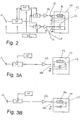
- FIG. 2 schematically shown circuitry provided.
- the sound signal to be transmitted is converted into an electrical one by a microphone 12 Converted signal, which is filtered in a signal processing stage 38 and is reinforced.
- the output signal of stage 38 is on two parallel filter stages 40, 42 given, each upstream of a power amplifier 44 or 46 are.
- the power amplifiers 44, 46 are connected to the connections 36 and 28 of the coil 32 or the piezo disk 22 connected.
- a micro controller 48 is used to control the Levels 38 and 40 42 are provided, the micro-controller 48 being from stage 38 Information regarding the spectral composition of what is currently being processed there Receives signal.
- an implantable battery or accumulator unit 50 is provided to supply power to the microphone 12, the stages 38, 40, 42, the micro-controller 48 and the power amplifier 44, 46 is preferred.
- the micro-controller 48 controls the filter stages 40, 42 in such a way that, depending on the frequency or the frequency center of the signal currently being processed in stage 38, either the piezo disk 22 and / or the coil 32 are excited with the signal to be transmitted.
- the micro-controller 48 can be designed such that the coil 32 is excited in a first frequency band, which ranges from a first frequency f 1 of the vibrations to be generated on the coupling element 20 to a separation frequency f T , and in a second Frequency band, which extends from the separation frequency f T to a second frequency f 2 of the vibrations to be generated on the coupling element, which is greater than the first frequency f 1 , the piezo disk 22 is excited.
- the micro-controller 48 is preferably programmable with respect to the separation frequency f T.
- FIG. 1 and 2 are the electromagnetic embodiment Transducer (coil 32) and the piezo transducer (disk 22) galvanically decoupled. This allows, for example, the use of double bridge amplifiers for control of the two converters 22 and 32.
- a separate control of the electromagnetic Transducer and the piezo transducer can also be achieved when, as in FIG. 2 is indicated by dashed lines, instead of in solid lines separate ground connections shown, only one common ground connection 52 is provided for the electromagnetic transducer and the piezo transducer a connecting wire 34 of the coil 32 is then not led to the outside, but internally connected to the housing 14.
- This embodiment has the advantage that only three connection poles must be provided on the converter 10, which also Hermetic execution simplified.
- FIG. 3A and 3B two embodiments are shown, in which one separate control of the electromagnetic transducer and the piezo transducer in favor of simplifying the overall converter.
- the electromagnetic transducer and the piezo transducer can in a parallel connection (FIG. 3A) or a series connection (FIG. 3B) be switched.
- FIG. 2 it will be from that Microphone 12 generates an electrical signal in the microcontroller 48 controlled level 38 filtered and amplified. However, the output signal can now can be fed directly to a power amplifier 162 without further filter stages the connections 160 is connected.
- the frequency response converter 10 thus results from the superposition of the frequency responses of the piezo transducer and the electromagnetic transducer, which, if appropriate Choice of the design of the mechanical converter components both a sufficiently strong one at low frequencies as well as at high frequencies Deflection of the membrane 18 can be achieved.
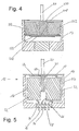
- FIG. 4 is a schematic of an alternative mechanical coupling of the electromagnetic Transducer and the piezo transducer shown. It is parallel to a second membrane forms a first membrane 218 forming an end wall of the housing 214
- Membrane 270 is provided inside the housing 214, on the underside, i.e. on the side facing away from the first membrane 218, a piezo disk 222 is attached to excite the second membrane 270.
- On top of the second Membrane 270 is attached to one end of a permanent magnet 230, the other of which End is attached to the first membrane 218, so that the permanent magnet 230 provides a mechanical coupling of the two membranes 218 and 270.
- the permanent magnet 230 is displaceable like in all other embodiments arranged within a coil 232, of which it is excited when the Coil 232 is driven to vibrate.
- the driver steers Magnet 230 both diaphragms 218 and 270 out.
- the piezo disc is excited 222 by applying a voltage, this causes a deflection of the second Membrane 270.
- This deflection is via the mechanical coupling transfer the magnet 230 to the first diaphragm 218, which causes them to accordingly is deflected and in turn a deflection of the coupling element 20 causes.
- connection or connection of the piezo disk 222 and the coil 232 can in the same way as outlined above, i.e. frequency dependent separate control in galvanic isolation or with common ground or common control in parallel or series connection.
- the embodiment according to FIG. 5 differs from that of FIG. 1 only in that the permanent magnet 30 through a central opening 23 of the piezo disc 22 passes through and with the piezo disk 22 facing side the membrane 18 is firmly connected in the center of the membrane.
- FIG. FIG. 6 shows an implanted hearing device, designated 51 overall, which is labeled is equipped with a converter 10 of the type explained above.
- the hearing aid 51 also has an accumulator unit 53, a charging / receiving coil 54 and an electronics module 55 on Components 53, 54 and 55 are in one hermetically sealed housing 56 housed, which is implantable in the mastoid 57.
- the converter 10 and a microphone 58 are connected to the electronics module 55 via lines 59 or 60 connected.
- the coupling element 20 is with the ossicle chain 62 coupled.
- a portable charging unit 63 includes a charging transmitter coil 64, which is used to transcutaneously charge the accumulator unit 53 with the charging / receiving coil 54 can be coupled inductively.
- a remote control unit is included 65 indicated.
- Such a hearing aid is known, for example, from US Pat. No. 5,277,694 and therefore requires no further description.
Landscapes
- Physics & Mathematics (AREA)
- Engineering & Computer Science (AREA)
- Acoustics & Sound (AREA)
- Signal Processing (AREA)
- Electromagnetism (AREA)
- Prostheses (AREA)
- Electrostatic, Electromagnetic, Magneto- Strictive, And Variable-Resistance Transducers (AREA)
- Piezo-Electric Transducers For Audible Bands (AREA)
Applications Claiming Priority (2)
| Application Number | Priority Date | Filing Date | Title |
|---|---|---|---|
| DE19840211 | 1998-09-03 | ||
| DE19840211A DE19840211C1 (de) | 1998-09-03 | 1998-09-03 | Wandler für teil- oder vollimplantierbare Hörgeräte |
Publications (3)
| Publication Number | Publication Date |
|---|---|
| EP0984665A2 true EP0984665A2 (fr) | 2000-03-08 |
| EP0984665A3 EP0984665A3 (fr) | 2006-05-17 |
| EP0984665B1 EP0984665B1 (fr) | 2008-08-06 |
Family
ID=7879709
Family Applications (1)
| Application Number | Title | Priority Date | Filing Date |
|---|---|---|---|
| EP98121613A Expired - Lifetime EP0984665B1 (fr) | 1998-09-03 | 1998-11-12 | Dispositif transducteur pour prothèse auditive partiellement ou totalement implantée |
Country Status (6)
| Country | Link |
|---|---|
| US (1) | US6123660A (fr) |
| EP (1) | EP0984665B1 (fr) |
| AU (1) | AU760240B2 (fr) |
| CA (1) | CA2270127C (fr) |
| DE (2) | DE19840211C1 (fr) |
| DK (1) | DK0984665T3 (fr) |
Cited By (3)
| Publication number | Priority date | Publication date | Assignee | Title |
|---|---|---|---|---|
| US6537199B1 (en) | 1999-07-26 | 2003-03-25 | Phonak Ag | Arrangement for mechanical coupling of a driver to a coupling site of the ossicular chain |
| US6547715B1 (en) | 1999-07-08 | 2003-04-15 | Phonak Ag | Arrangement for mechanical coupling of a driver to a coupling site of the ossicular chain |
| US20210280442A1 (en) * | 2020-03-09 | 2021-09-09 | Tsc Inc. | Apparatus for sensing wafer loading state using sound wave sensor |
Families Citing this family (26)
| Publication number | Priority date | Publication date | Assignee | Title |
|---|---|---|---|---|
| WO1999063785A2 (fr) | 1998-06-05 | 1999-12-09 | St. Croix Medical, Inc. | Procede et dispositif destines a attenuer l'effet de retroaction dans des systemes d'assistance auditive implantables |
| DE19859171C2 (de) * | 1998-12-21 | 2000-11-09 | Implex Hear Tech Ag | Implantierbares Hörgerät mit Tinnitusmaskierer oder Noiser |
| DE10015421C2 (de) | 2000-03-28 | 2002-07-04 | Implex Ag Hearing Technology I | Teil- oder vollimplantierbares Hörsystem |
| DE10018360C2 (de) | 2000-04-13 | 2002-10-10 | Cochlear Ltd | Mindestens teilimplantierbares System zur Rehabilitation einer Hörstörung |
| DE10018334C1 (de) * | 2000-04-13 | 2002-02-28 | Implex Hear Tech Ag | Mindestens teilimplantierbares System zur Rehabilitation einer Hörstörung |
| DE10018361C2 (de) | 2000-04-13 | 2002-10-10 | Cochlear Ltd | Mindestens teilimplantierbares Cochlea-Implantat-System zur Rehabilitation einer Hörstörung |
| DE10031832C2 (de) * | 2000-06-30 | 2003-04-30 | Cochlear Ltd | Hörgerät zur Rehabilitation einer Hörstörung |
| DE10039401C2 (de) | 2000-08-11 | 2002-06-13 | Implex Ag Hearing Technology I | Mindestens teilweise implantierbares Hörsystem |
| DE10041726C1 (de) | 2000-08-25 | 2002-05-23 | Implex Ag Hearing Technology I | Implantierbares Hörsystem mit Mitteln zur Messung der Ankopplungsqualität |
| DE10047388C1 (de) | 2000-09-25 | 2002-01-10 | Implex Hear Tech Ag | Mindestens teilweise implantierbares Hörsystem |
| DE10114838A1 (de) | 2001-03-26 | 2002-10-10 | Implex Ag Hearing Technology I | Vollständig implantierbares Hörsystem |
| US6730015B2 (en) | 2001-06-01 | 2004-05-04 | Mike Schugt | Flexible transducer supports |
| AU2003242912B2 (en) * | 2002-05-31 | 2008-10-16 | Med-El Elektromedizinische Geraete Gmbh | Low power signal transmission |
| AU2006209223B2 (en) * | 2005-01-27 | 2012-04-12 | Cochlear Limited | Implantable medical device |
| WO2007011806A2 (fr) * | 2005-07-18 | 2007-01-25 | Soundquest, Inc. | Dispositif auditif place derriere l'oreille |
| US20070127757A2 (en) * | 2005-07-18 | 2007-06-07 | Soundquest, Inc. | Behind-The-Ear-Auditory Device |
| EP2255545A2 (fr) * | 2008-02-07 | 2010-12-01 | Advanced Bionics AG | Prothèse auditive partiellement implantable |
| US8216287B2 (en) * | 2008-03-31 | 2012-07-10 | Cochlear Limited | Tangential force resistant coupling for a prosthetic device |
| CN201234336Y (zh) * | 2008-07-18 | 2009-05-06 | 比亚迪股份有限公司 | 一种听筒单元 |
| US20120136197A1 (en) * | 2010-11-30 | 2012-05-31 | Van Gerwen Peter B J | Hearing prosthesis having a flexible elongate energy transfer mechanism |
| WO2012076060A2 (fr) * | 2010-12-09 | 2012-06-14 | Advanced Bionics Ag | Organe de commande implantable d'une aide auditive |
| DE202012012867U1 (de) * | 2011-12-08 | 2014-01-30 | Biotronik Se & Co. Kg | Medizinisches Implantat und medizinische Anordnung |
| HUE027883T2 (en) * | 2013-05-08 | 2016-10-28 | Grieshaber Vega Kg | Vibration Level Switch |
| EP2875844B1 (fr) | 2013-11-25 | 2018-01-03 | BIOTRONIK SE & Co. KG | Dispositif d'électrodes implantables, notamment pour appareils cardiologiques, comme un stimulateur cardiaque |
| US10321247B2 (en) | 2015-11-27 | 2019-06-11 | Cochlear Limited | External component with inductance and mechanical vibratory functionality |
| EP4195704A3 (fr) * | 2021-12-07 | 2023-10-04 | Oticon Medical A/S | Prothèse auditive comprenant un ensemble piézoélectrique et un ensemble électromagnétique |
Citations (3)
| Publication number | Priority date | Publication date | Assignee | Title |
|---|---|---|---|---|
| US4628907A (en) * | 1984-03-22 | 1986-12-16 | Epley John M | Direct contact hearing aid apparatus |
| EP0499940A1 (fr) * | 1991-02-13 | 1992-08-26 | IMPLEX GmbH Spezialhörgeräte | Transducteur électromécanique pour appareils de correction auditive implantables |
| US5624376A (en) * | 1993-07-01 | 1997-04-29 | Symphonix Devices, Inc. | Implantable and external hearing systems having a floating mass transducer |
Family Cites Families (6)
| Publication number | Priority date | Publication date | Assignee | Title |
|---|---|---|---|---|
| GB1440724A (en) * | 1972-07-18 | 1976-06-23 | Fredrickson J M | Implantable electromagnetic hearing aid |
| US4800884A (en) * | 1986-03-07 | 1989-01-31 | Richards Medical Company | Magnetic induction hearing aid |
| DE3918086C1 (fr) * | 1989-06-02 | 1990-09-27 | Hortmann Gmbh, 7449 Neckartenzlingen, De | |
| US5259032A (en) * | 1990-11-07 | 1993-11-02 | Resound Corporation | contact transducer assembly for hearing devices |
| US5360388A (en) * | 1992-10-09 | 1994-11-01 | The University Of Virginia Patents Foundation | Round window electromagnetic implantable hearing aid |
| US6005955A (en) * | 1996-08-07 | 1999-12-21 | St. Croix Medical, Inc. | Middle ear transducer |
-
1998
- 1998-09-03 DE DE19840211A patent/DE19840211C1/de not_active Expired - Fee Related
- 1998-11-12 DE DE59814262T patent/DE59814262D1/de not_active Expired - Lifetime
- 1998-11-12 EP EP98121613A patent/EP0984665B1/fr not_active Expired - Lifetime
- 1998-11-12 DK DK98121613T patent/DK0984665T3/da active
-
1999
- 1999-04-21 AU AU23914/99A patent/AU760240B2/en not_active Ceased
- 1999-04-23 CA CA002270127A patent/CA2270127C/fr not_active Expired - Fee Related
- 1999-05-14 US US09/311,563 patent/US6123660A/en not_active Expired - Lifetime
Patent Citations (3)
| Publication number | Priority date | Publication date | Assignee | Title |
|---|---|---|---|---|
| US4628907A (en) * | 1984-03-22 | 1986-12-16 | Epley John M | Direct contact hearing aid apparatus |
| EP0499940A1 (fr) * | 1991-02-13 | 1992-08-26 | IMPLEX GmbH Spezialhörgeräte | Transducteur électromécanique pour appareils de correction auditive implantables |
| US5624376A (en) * | 1993-07-01 | 1997-04-29 | Symphonix Devices, Inc. | Implantable and external hearing systems having a floating mass transducer |
Cited By (3)
| Publication number | Priority date | Publication date | Assignee | Title |
|---|---|---|---|---|
| US6547715B1 (en) | 1999-07-08 | 2003-04-15 | Phonak Ag | Arrangement for mechanical coupling of a driver to a coupling site of the ossicular chain |
| US6537199B1 (en) | 1999-07-26 | 2003-03-25 | Phonak Ag | Arrangement for mechanical coupling of a driver to a coupling site of the ossicular chain |
| US20210280442A1 (en) * | 2020-03-09 | 2021-09-09 | Tsc Inc. | Apparatus for sensing wafer loading state using sound wave sensor |
Also Published As
| Publication number | Publication date |
|---|---|
| CA2270127A1 (fr) | 2000-03-03 |
| EP0984665A3 (fr) | 2006-05-17 |
| DE59814262D1 (de) | 2008-09-18 |
| DE19840211C1 (de) | 1999-12-30 |
| EP0984665B1 (fr) | 2008-08-06 |
| AU2391499A (en) | 2000-03-16 |
| CA2270127C (fr) | 2001-10-16 |
| US6123660A (en) | 2000-09-26 |
| DK0984665T3 (da) | 2008-11-24 |
| AU760240B2 (en) | 2003-05-08 |
Similar Documents
| Publication | Publication Date | Title |
|---|---|---|
| EP0984665B1 (fr) | Dispositif transducteur pour prothèse auditive partiellement ou totalement implantée | |
| DE19882593B4 (de) | Implantierbares Hörsystem mit mehreren Wandlern | |
| EP0984663B1 (fr) | Dispositif transducteur pour prothèses auditives partiellement ou totalment implantées | |
| DE19882589B3 (de) | Wandler mit piezoelektrischem Film | |
| EP1011295B1 (fr) | Transducteur hermétiquement étanche pour prothèse auditive et prothèse auditive avec ce transducteur | |
| DE69634700T2 (de) | Implantierbares hörhilfegerät | |
| EP1179969B1 (fr) | Système auditif au moins partiellement implantable | |
| DE3918086C1 (fr) | ||
| DE10046938A1 (de) | Mindestens teilimplantierbares Hörsystem mit direkter mechanischer Stimulation eines lymphatischen Raums des Innenohres | |
| DE102009014770A1 (de) | Schwingungserzeuger | |
| EP0499940A1 (fr) | Transducteur électromécanique pour appareils de correction auditive implantables | |
| DE102010009453A1 (de) | Schallwandler zum Einsetzen in ein Ohr | |
| EP0919108A1 (fr) | Transducteur a film piezo-electrique destine a etre utilise dans un systeme auditif implantable | |
| WO1998006236A1 (fr) | Transducteur pour oreille moyenne | |
| EP3254474B1 (fr) | Implant électroacoustique | |
| WO1998006235A1 (fr) | Systeme de prothese auditive implantable avec transducteurs multiples | |
| EP1422971B1 (fr) | Transducteur implantable pour des systèmes auditifs et procédé d'ajustement de la réponse en fréquence d'un tel transducteur | |
| DE102005059270A1 (de) | Elektroakustische Wandlereinrichtung mit Kohlenstoffröhrchen und damit ausgestattete Hörvorrichtung | |
| EP1439737B1 (fr) | Transducteur électromécanique implantable | |
| WO2011051469A1 (fr) | Convertisseur électromécanique | |
| DE3230060A1 (de) | Piezoelektrischer summer | |
| EP1119219B1 (fr) | Transducteur électroacoustique en miniature | |
| WO2019001930A1 (fr) | Ensemble transducteur acoustique comprenant une unité mems | |
| WO1999008480A2 (fr) | Transducteur d'oreille moyenne | |
| DE102018220731B3 (de) | Elektroakustischer Wandler zur Implantation in ein Ohr, Verfahren zur Herstellung eines solchen und Cochlea-Implantatsystem |
Legal Events
| Date | Code | Title | Description |
|---|---|---|---|
| PUAI | Public reference made under article 153(3) epc to a published international application that has entered the european phase |
Free format text: ORIGINAL CODE: 0009012 |
|
| AK | Designated contracting states |
Kind code of ref document: A2 Designated state(s): AT BE CH CY DE DK ES FI FR GB GR IE IT LI LU MC NL PT SE |
|
| AX | Request for extension of the european patent |
Free format text: AL;LT;LV;MK;RO;SI |
|
| RAP1 | Party data changed (applicant data changed or rights of an application transferred) |
Owner name: IMPLEX AKTIENGESELLSCHAFT HEARING TECHNOLOGY |
|
| RAP1 | Party data changed (applicant data changed or rights of an application transferred) |
Owner name: PHONAK AG |
|
| PUAL | Search report despatched |
Free format text: ORIGINAL CODE: 0009013 |
|
| AK | Designated contracting states |
Kind code of ref document: A3 Designated state(s): AT BE CH CY DE DK ES FI FR GB GR IE IT LI LU MC NL PT SE |
|
| AX | Request for extension of the european patent |
Extension state: AL LT LV MK RO SI |
|
| 17P | Request for examination filed |
Effective date: 20061102 |
|
| AKX | Designation fees paid |
Designated state(s): CH DE DK FR GB LI |
|
| GRAP | Despatch of communication of intention to grant a patent |
Free format text: ORIGINAL CODE: EPIDOSNIGR1 |
|
| GRAS | Grant fee paid |
Free format text: ORIGINAL CODE: EPIDOSNIGR3 |
|
| GRAA | (expected) grant |
Free format text: ORIGINAL CODE: 0009210 |
|
| AK | Designated contracting states |
Kind code of ref document: B1 Designated state(s): CH DE DK FR GB LI |
|
| REG | Reference to a national code |
Ref country code: GB Ref legal event code: FG4D Free format text: NOT ENGLISH |
|
| REG | Reference to a national code |
Ref country code: CH Ref legal event code: NV Representative=s name: TROESCH SCHEIDEGGER WERNER AG Ref country code: CH Ref legal event code: EP |
|
| REF | Corresponds to: |
Ref document number: 59814262 Country of ref document: DE Date of ref document: 20080918 Kind code of ref document: P |
|
| REG | Reference to a national code |
Ref country code: DK Ref legal event code: T3 |
|
| PLBE | No opposition filed within time limit |
Free format text: ORIGINAL CODE: 0009261 |
|
| STAA | Information on the status of an ep patent application or granted ep patent |
Free format text: STATUS: NO OPPOSITION FILED WITHIN TIME LIMIT |
|
| 26N | No opposition filed |
Effective date: 20090507 |
|
| PGFP | Annual fee paid to national office [announced via postgrant information from national office to epo] |
Ref country code: FR Payment date: 20101109 Year of fee payment: 13 Ref country code: DK Payment date: 20101027 Year of fee payment: 13 |
|
| PGFP | Annual fee paid to national office [announced via postgrant information from national office to epo] |
Ref country code: CH Payment date: 20101027 Year of fee payment: 13 |
|
| PGFP | Annual fee paid to national office [announced via postgrant information from national office to epo] |
Ref country code: GB Payment date: 20101026 Year of fee payment: 13 |
|
| REG | Reference to a national code |
Ref country code: CH Ref legal event code: PL |
|
| REG | Reference to a national code |
Ref country code: DK Ref legal event code: EBP |
|
| GBPC | Gb: european patent ceased through non-payment of renewal fee |
Effective date: 20111112 |
|
| PG25 | Lapsed in a contracting state [announced via postgrant information from national office to epo] |
Ref country code: LI Free format text: LAPSE BECAUSE OF NON-PAYMENT OF DUE FEES Effective date: 20111130 Ref country code: CH Free format text: LAPSE BECAUSE OF NON-PAYMENT OF DUE FEES Effective date: 20111130 |
|
| REG | Reference to a national code |
Ref country code: FR Ref legal event code: ST Effective date: 20120731 |
|
| PG25 | Lapsed in a contracting state [announced via postgrant information from national office to epo] |
Ref country code: DK Free format text: LAPSE BECAUSE OF NON-PAYMENT OF DUE FEES Effective date: 20111130 Ref country code: GB Free format text: LAPSE BECAUSE OF NON-PAYMENT OF DUE FEES Effective date: 20111112 |
|
| PG25 | Lapsed in a contracting state [announced via postgrant information from national office to epo] |
Ref country code: FR Free format text: LAPSE BECAUSE OF NON-PAYMENT OF DUE FEES Effective date: 20111130 |
|
| PGFP | Annual fee paid to national office [announced via postgrant information from national office to epo] |
Ref country code: DE Payment date: 20121130 Year of fee payment: 15 |
|
| REG | Reference to a national code |
Ref country code: DE Ref legal event code: R119 Ref document number: 59814262 Country of ref document: DE Effective date: 20140603 |
|
| PG25 | Lapsed in a contracting state [announced via postgrant information from national office to epo] |
Ref country code: DE Free format text: LAPSE BECAUSE OF NON-PAYMENT OF DUE FEES Effective date: 20140603 |