EP0984637A2 - Projection display system for reflective light valves - Google Patents
Projection display system for reflective light valves Download PDFInfo
- Publication number
- EP0984637A2 EP0984637A2 EP99117264A EP99117264A EP0984637A2 EP 0984637 A2 EP0984637 A2 EP 0984637A2 EP 99117264 A EP99117264 A EP 99117264A EP 99117264 A EP99117264 A EP 99117264A EP 0984637 A2 EP0984637 A2 EP 0984637A2
- Authority
- EP
- European Patent Office
- Prior art keywords
- light
- component
- red
- blue
- light component
- Prior art date
- Legal status (The legal status is an assumption and is not a legal conclusion. Google has not performed a legal analysis and makes no representation as to the accuracy of the status listed.)
- Granted
Links
- 238000001914 filtration Methods 0.000 claims description 21
- 230000007246 mechanism Effects 0.000 claims description 14
- 230000003098 cholesteric effect Effects 0.000 claims description 11
- 238000005286 illumination Methods 0.000 claims description 11
- 230000010287 polarization Effects 0.000 description 21
- 238000009826 distribution Methods 0.000 description 18
- 230000003287 optical effect Effects 0.000 description 12
- 239000004973 liquid crystal related substance Substances 0.000 description 10
- 230000008901 benefit Effects 0.000 description 9
- 239000000463 material Substances 0.000 description 5
- 230000005684 electric field Effects 0.000 description 2
- 238000003384 imaging method Methods 0.000 description 2
- 238000000034 method Methods 0.000 description 2
- 238000005215 recombination Methods 0.000 description 2
- 230000006798 recombination Effects 0.000 description 2
- 239000000126 substance Substances 0.000 description 2
- 238000001429 visible spectrum Methods 0.000 description 2
- 238000009125 cardiac resynchronization therapy Methods 0.000 description 1
- 238000000576 coating method Methods 0.000 description 1
- 238000004737 colorimetric analysis Methods 0.000 description 1
- 239000012141 concentrate Substances 0.000 description 1
- 230000001419 dependent effect Effects 0.000 description 1
- 230000000694 effects Effects 0.000 description 1
- 230000003993 interaction Effects 0.000 description 1
- 238000005259 measurement Methods 0.000 description 1
- 238000012986 modification Methods 0.000 description 1
- 230000004048 modification Effects 0.000 description 1
- 238000004806 packaging method and process Methods 0.000 description 1
- 238000011045 prefiltration Methods 0.000 description 1
- 230000009467 reduction Effects 0.000 description 1
- 238000000926 separation method Methods 0.000 description 1
- 239000007787 solid Substances 0.000 description 1
Images



Classifications
-
- H—ELECTRICITY
- H04—ELECTRIC COMMUNICATION TECHNIQUE
- H04N—PICTORIAL COMMUNICATION, e.g. TELEVISION
- H04N9/00—Details of colour television systems
- H04N9/12—Picture reproducers
- H04N9/31—Projection devices for colour picture display, e.g. using electronic spatial light modulators [ESLM]
- H04N9/3102—Projection devices for colour picture display, e.g. using electronic spatial light modulators [ESLM] using two-dimensional electronic spatial light modulators
- H04N9/3105—Projection devices for colour picture display, e.g. using electronic spatial light modulators [ESLM] using two-dimensional electronic spatial light modulators for displaying all colours simultaneously, e.g. by using two or more electronic spatial light modulators
-
- H—ELECTRICITY
- H04—ELECTRIC COMMUNICATION TECHNIQUE
- H04N—PICTORIAL COMMUNICATION, e.g. TELEVISION
- H04N9/00—Details of colour television systems
- H04N9/12—Picture reproducers
- H04N9/31—Projection devices for colour picture display, e.g. using electronic spatial light modulators [ESLM]
- H04N9/3141—Constructional details thereof
- H04N9/315—Modulator illumination systems
- H04N9/3167—Modulator illumination systems for polarizing the light beam
Definitions
- This invention relates to projection display systems which use reflective spatial light modulators, and specifically, to such systems which incorporate reflective liquid crystal devices.
- the system shown in Fig. 1 illustrates the essential components of the optical portion of a projection display system having three reflective spatial light modulators in the form of liquid crystal display (LCD) panels, also referred to as liquid crystal light valves (LCLV).
- the prior art system depicted generally at 10 includes a light source 12, an illumination mechanism for collecting the light and concentrating it onto the light valves, shown generally at 14, a polarizing mechanism for polarizing the light, if the light valves modulate via polarization effects, shown generally at 16, a splitting mechanism for splitting the illumination into three color bands to separately illuminate the three light valves, shown generally at 18, a recombining mechanism for recombining the three light distributions after reflecting from the light valves, shown generally at 20, and a projection mechanism for projecting the combined images onto a viewing screen, shown generally at 22.
- Lamp 24 and lamp reflector 26 produce and concentrate the light for this system.
- a series of dichroic filters 28, 30 is used to split the light from the lamp into separate red, green, and blue components.
- the light in each of the three components, or channels, is then polarized with a polarizing beam splitter (PBS) 32, 34, 36, and illuminates three separate LCDs, 38, 40, 42.
- PBS polarizing beam splitter
- the LCDs selectively modify the polarization of the light reflected from them allowing some portion of the light to pass back through the PBS.
- a second series of dichroic filters, 44, 46 is used to recombine the modulated light distributions and pass them on to a projection lens 48 imaging all three LCDs onto the viewing screen.
- Fig. 1 The configuration shown in Fig. 1 is functional and has been used to implement projection display system products.
- the large number of components in this architecture is cumbersome, and necessitates a relatively large physical size of the system.
- the most serious drawback to these systems is the requirement of a large back working distance for the projection lens.
- a single filter, or PBS plate, tilted at 45 degrees requires an optical path length equal to or greater than the active width of the LCD panel. It may be seen in Fig. 1 that two of the three channels, green and red, require a PBS and two dichroic filters. These channels require a minimum optical path length between the LCD and the projection lens of three times the active width of the LCD. The blue channel in Fig. 1 requires only one PBS and a single dichroic filter, but the path length must be equal to the other two channels for in-focus registration of all three images on the viewing screen. The actual optical path length for the projection lens must also account for the divergence of the light after reflecting off the LCD panel.
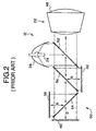
- System configuration 50 incorporates two of these simplifications.
- the first is the use of a single PBS 52 immediately after lamp 24, replacing the three PBS plates of the Fig. 1 system configuration.
- Single PBS 52 polarizes the broadband output of the lamp prior to the color splitting operation and thus functions as the amplitude modulation control mechanism for all three LCDs. This requires that the PBS function over the entire visible spectrum.
- the second simplification is to utilize the same set of dichroics to split the light into the three color channels and to recombine the reflected light prior to the projection optic. This requires that the dichroic filter passbands be carefully controlled since there are now only two filters 54, 56, to control the whole system colorimetry. The savings in system complexity is readily evident.
- One system difficulty not addressed by the configuration in Fig. 2 is the reduction in the back working distance of the projection lens.
- the projection lens must still work over a distance that is a minimum of three times the active width of the LCD.
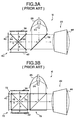
- a solution to this problem is found by recognizing that the operation of the dichroic filters is still the same even if the dichroic structures are crossed as shown in system 60 in Fig. 3a. This allows the back working distance to be reduced by 33% over the systems of Figs. 1 or 2, to a minimum of twice the active width of the LCD.
- crossing plate dichroics 62, 64 introduces a problem because the operation at the intersection of the two plates is usually disrupted by the thickness of the plates, producing a seam in the middle of the image, where the images of the three LCD panels are totally or partially obscured by the plate intersection.
- Fig. 3b shows the introduction of a four piece color cube filter, shown generally at 72.
- Dichroic filters 74, 76 are deposited on the surfaces of the four cube segments and the pieces are then glued together to form a solid cube with the dichroics sealed in the interior across the cube diagonals. If properly assembled this arrangement eliminates most of the obstruction of the central crossover of the two dichroic layers. However, this assembly is precise and the color cube component is expensive because of the difficulty in assembly.
- Fig. 3b also shows the use of a polarizing beam splitter cube 78. This component is a common assembly for optical systems and is not an expensive addition due to the significantly less stringent assembly requirements.
- the state-of-the-art in system architectures for reflective LCDs includes several arrangements, each with particular advantages and disadvantages.
- a desired alternative is a system that has the small back working distance advantages of the systems shown in Figs. 3a and 3b, without the costly addition of a precisely assembled crossed dichroic filter cube.
- United States Patent No. 5,648,860 to Ooi et al ., July 15, 1997, uses two dichroic plates to separate the light into the three color channels and to recombine the light reflected from the LCDs.
- the angles of the plates used in this configuration are not 45 degrees and are set to try to reduce the back working distance for the projection optics.
- the key invention of this patent appears to be the use of positive lens elements directly in contact with the LCD panels to collimate the incoming illumination and to converge the reflected light, and the use of "cone-like" prisms to affect the matched convergence of the illuminating light. In all other aspects this system is essentially the same as that of Fig. 2.
- United States Patent No. 5,658,060 to Dove, is a system having a set of external dichroic filters that separate the light into the three color paths.
- the light in each path is separately polarized before illuminating the light valves.
- the reflected light is recombined through a special prism arrangement, usually referred to as a Philips prism.
- the Philips prism is used to try to reduce the back working distance requirements of the projection lens.
- this system uses a prism for recombination, it is architecturally equivalent to the system in Fig. 1.
- the reference also describes another embodiment that uses a cube beam splitter for recombining the light output but continues to use separate dichroics to affect the initial split of the light into three color paths and to use separate PBSs for each light valve.
- references describing transmissive light modulators include United States Patent No. 5,321,448, to Ogawa, June 14, 1994, and United States Patent No. 5,626,409, to Nakayama et al ., May 6, 1997, the latter of which describes a system which is the transmissive equivalent of the system in Fig. 1.
- the light from the lamp is divided into the three-color paths by a set of dichroic filters. After passing through the three light valves, the modulated light distributions are recombined using a separate set of dichroic filters.
- the '448 reference uses a set of dichroic filters to divide the lamp output into the three-color paths, and a separate set of dichroic filters, in the form of a color cube prism, to recombine the modulated light.
- This later configuration is the most common architecture presently used for transmissive light valves.
- a projection display system for reflective light valves includes a light source for generating a light beam having red-green-blue (RGB) light components, wherein the red light component is p-polarized and the green and blue light components are s-polarized; a reflector structure having plural polarizing beam splitters (PBS) and dichroic filters (DF) therein, wherein each PBS and DF reflects a preselected light component and transmits a different preselected light component, and a LCD panel for generating a light-component-specific image associated with each light component; and a projection lens for projecting an image combined from the light-component-specific images from the LCDs; wherein a light-component-specific image passes through one and only one PBS and through one and only one DF between the LCD and the projection lens.
- RGB red-green-blue
- An object of this invention is to provide a projection system for reflective liquid crystal light valves that has a small back working distance for the projection lens.
- Another object of this invention is to provide a projection system for reflective liquid crystal light valves that has an projection path free from crossed dichroics obstructions.
- Yet another object of this invention is to provide a projection system for reflective liquid crystal light valves that has a relatively simple configuration of the components that are used to split up and recombine the three color light distributions.
- Another object of this invention is to provide a projection system for reflective liquid crystal light valves that is more compact than known projection systems.
- a further object of this invention is to provide a projection system for reflective liquid crystal light valves that may be manufactured at a reduced cost compared to existing systems.
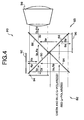
- the projection display system of the invention is shown generally at 80 in Fig. 4.
- System 80 includes a light source 82 and a projection system 83.
- Projection system 83 includes two dichroic filters (DF) 84, 86, and two polarizing beam splitters (PBS) 88, 90, to split up the incoming white light from light source 82 into RGB components before directing each light beam component to a specific light valve, or liquid crystal display (LCD), 92, 94, 96.
- LCDs 92, 94, 96 each provide a light-component-specific image, which is illuminated by the light beam component and reflected from the face of the LCD, carrying a color image component. The color image components are then recombined, and the reflected light is directed to projection lens 98.
- a requirement for proper operation of projection system 83 is that the input illumination is pre-filtered and polarized so that the green and blue distributions are s-polarized and the red distribution is p-polarized.
- s-polarized light has its electric field vector linearly polarized perpendicular to the plane of the figure and p-polarized light has its electric field vector linearly polarized in the plane of the figure.
- the pre-filtering mechanism will be described later herein.
- DFs 84 and 86 are arranged in a substantially straight line within projection system 83, as are PBSs 88, 90.
- the DFs and PBSs are arranged to intersect their respective substantially straight lines adjacent the midpoints thereof in a normal relationship.
- the optics are arranged in a substantially "X" shaped configuration, with the filters and beam splitters each joined adjacent an edge thereof.
- DF 84 and DF 86 it will be appreciated that the reflective coatings are disposed on one side only of the filter, i.e ., as viewed in Fig. 4, DF 84 is coated on its upper surface while DF 86 is coated on its lower surface. The coated surfaces line up in the "X" shaped configuration.
- the incoming light first encounters blue-transmitting dichroic filter 84.
- the s-polarized blue light is transmitted while the s-polarized green light and p-polarized red light are reflected.
- the blue light passes on to PBS 88 where, because it is s-polarized, it reflects to first LCD light valve 96, which is a blue light modulator.
- LCD 96 modulates the polarization of the light by rotating the direction of polarization in proportion to the electrical signals provided to the device.
- the reflected light is thus a combination of s-polarized and p-polarized light.
- the s-polarized portion again reflects back toward the incoming illumination and the p-polarized portion is transmitted on to blue-reflecting dichroic 86.
- the blue light will reflect off second dichroic filter 86 and through projection lens 98, to an image display, such as a projection screen.
- the green and red light that is reflected first dichroic filter 84 propagates to second PBS 90.
- the p-polarized red light is transmitted through PBS 90 to second LCD 92, a red light modulator, while the s-polarized green light is reflected to third LCD 94, a green light modulator.
- LCDs 92, 94 modulate the light distributions, and after the reflected distributions return to PBS 90, only the p-polarized portion of the green light and the s-polarized portion of the red light pass over to blue-reflecting dichroic filter 86. The other portions of these two distributions are again returned toward the incoming illumination. Because dichroic filter 86 transmits both red and green, these two distributions are combined with the blue light from the other path and pass through projection lens 98 to the image display. Dichroic filter 86 acts as an image recombiner in this embodiment.
- Fig. 4 It may be seen in Fig. 4 that the light path from any LCD to projection lens 96 encounters one and only one PBS and one and only one dichroic filter.
- the optical path length has been reduced to a minimum of twice the active width of the LCD panel.
- Reflective LCD panels typically used in projection systems of the type described herein may vary in size from approximately 8 mm to 5 cm, diagonal measurement.
- the optical path length may be no less than approximately 1.6 cm to 10 cm. In this configuration, however, it is not necessary to cross any color filtering or polarizing structure in the optical path. There is, therefore, no obstruction of any kind in the projection path as in the configurations of Fig. 3. This represents a significant performance advantage.
- the configuration of Fig. 4 may also be implemented easily with thin plate dichroics and PBSs, which represents a significant cost advantage over a cube prism configuration.
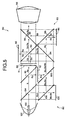
- Projection display system 80 includes projection system 83 of Fig. 4, and a specific embodiment of a pre-filtering illumination mechanism required to obtain the special combination of input light for the proper operation of this architecture.
- Light source 82 includes a lamp 100 and reflector 102, and a number of DFs and PBSs.
- An unpolarized white light beam from lamp 100 is incident on a red-transmitting dichroic filter 104.
- the blue and green light from the lamp reflect from filter 104 to a PBS 106.
- the s-polarized portions of the green and blue light then reflect off the PBS toward a red reflecting dichroic filter 108, while the p-polarized green and blue portions are absorbed by a stop 109.
- the two distributions that pass through dichroic filter 108 provide the s-polarized blue and green input to projection system 83.
- the unpolarized red light transmitted by dichroic filter 104 is polarized by PBS 110, and the s-polarized portion is reflected toward red-reflecting dichroic filter 108, while the p-polarized red portion is absorbed by stop 111.
- the light Before impinging the dichroic, the light passes through a half wave plate 112 that rotates its polarization direction by 90 degrees.
- the red light is now p-polarized, reflects off red-reflecting dichroic 108 and provides the p-polarized red light input to projection system 83.
- the pre-filtering configuration has the advantage of being implemented with fairly standard and inexpensive filtering components.
- One disadvantage of this arrangement is that the portions of the light distributions that pass through PBSs 106, 110 and hit stops 109, 111, respectively, are absorbed and lost. This light is half of the total light output from lamp 100. This level of light loss is typical of LCD projection systems that do not use polarization converters or recyclers.
- a second disadvantage is the additional size of the pre-filtering optics adding to the whole system. While the size of this complete system is smaller than the original reflective architecture described in Fig. 1, that uses simple plate filters and PBSs, it is quite a bit larger than the configurations of Figs 2 or 3.
- Filter stack 113 uses specially designed cholesteric color filters 114, 116, 118.
- Cholesterics are chemical structures which have a spirally twisted molecular alignment. These materials have a special optical property that causes light of a wavelength that is equal to the pitch of the cholesteric spiral to be completely reflected if the light is circularly polarized, with the direction of circularity being the same as the direction of the cholesteric spiral.
- a cholesteric filter may be set up to reflect the left or right handed circular polarized portion of one color of light and to transmit the other handedness.
- the cholesteric does not affect any other color of light, transmitting both polarizations.
- the chemical structures of cholesterics may be manipulated to cause this special reflecting property to extend over a fairly broad range of wavelengths.
- the bands may be timed to give just about any desired color passband for the portion of light that is reflected.
- the pre-filtering operation of filter stack 113 is as follows: Unpolarized white light is incident on the stack from the left.
- First filter 114 is designed to reflect the right-handed circularly polarized portion of red light, and transmit the left-handed circularly polarized portion of the red light, and all polarizations of green and blue light.
- Second filter 116 is designed to reflect the left-handed polarization portion of green light. The right-handed polarization portion of green light is transmitted along with the left-handed polarized portion of the red light and the unpolarized blue light.
- Third filter 118 is designed to reflect the left-handed polarization portion of blue light, and transmits the right-handed polarization portion of blue and the rest of the incident light, i.e ., the right-handed polarization portion of green light and the left-handed polarization portion of red light.
- Circular polarization may be turned into linear polarization by passing the light through a quarter wave plate 120.
- Right-handed polarized light will exit wave plate 120 as linearly polarized with the direction of polarization at +45 degrees to the crystalline optic axis of the wave plate material.
- Left-handed polarized light will also exit the wave plate linearly polarized, but the direction will be at - 45 degrees to the crystalline axis.
- the right-hand polarized green and blue light will exit as s-polarized and the left-hand polarized red light will exit as p-polarized. This is the desired input to the imaging portion of the projection architecture.
- the system shown in Fig. 7 uses pre-filtering stack 113 as part of light source 82 directly after lamp 100 to implement complete projection display system 80.
- System 80 is significantly smaller than the arrangement made with more conventional components in Fig. 5. The smaller size is the main advantage of this embodiment.
- This configuration has the same light loss problem as that of Fig. 5 because the cholesterics reflect half of the unpolarized light in their passband. This is again typical in many LCD projectors.
- Another disadvantage is the relative immaturity of the cholesteric materials. It is not clear at this point if the filtering materials will be as efficient or as durable as the dielectric stack materials used in dichroic filters and in PBSs.
- the system of Fig. 7 is a preferred embodiment if those questions may be satisfactorily answered.
- the embodiment of projection system 83 of system 80 is the preferred embodiment.
- the pre-filter must polarize green and red light with s-polarization and blue with p-polarization.
- the roles of LCD 92 and LCD 96 in modulating the red and blue light distributions are reversed, but in all other respects the system is equivalent. It is, however, undesirable to set this type of system up with the dichroics being green-reflecting and green-transmitting, which will have LCD 96 modulating the green light.
- Green dichroic filters have two band edges in the visible spectrum - one separating red and green and the other separating blue and green. The position of the band edges is highly dependent on the polarization of the light. If green dichroics are used, either red or blue light will have to be polarized in the opposite state from the green light and the filtering at the band edge between the two differing polarization states will be poorly controlled. In the system shown in Fig. 4, using blue dichroics, the band edges of both filters separate blue and green. Both of these light distributions have the same polarization when they are split apart by the first, blue-transmitting dichroic, and when they are recombined by the second, blue-reflecting dichroic. The filtering at the band edge in bath filters may therefore be well controlled. The same is true if red dichroics are used.
- Projection display system 122 depicted in Fig. 8, includes a projection system 124 having, in addition to the components of projection system 83, a blue-transmitting dichroic filter 126, located prior to projection lens 98, which replaces blue-reflecting filter 86 shown in Fig. 7.
- the result is to direct the recombined light distributions out of projection system 124 at ninety degrees from that of projection system 83 of Fig. 7.
- This alternative embodiment may offer packaging advantages for some products.
- the band edge of first blue-transmitting filter 84 in Fig. 8 is used to separate s-polarized blue and green light, while the second blue transmitting filter is used to recombine p-polarized blue and green light. For reasons mentioned in the previous paragraph, these are not identical filters.
Landscapes
- Engineering & Computer Science (AREA)
- Multimedia (AREA)
- Signal Processing (AREA)
- Liquid Crystal (AREA)
- Projection Apparatus (AREA)
- Devices For Indicating Variable Information By Combining Individual Elements (AREA)
Abstract
Description
Claims (15)
- A projection display system for reflective light valves comprising:a light source (82) for generating a light beam having red-green-blue (RGB) light components;a projection system (83) having plural polarizing beam splitter (88, 90) and dichroic filters (84, 86) therein, wherein each polarizing beam splitter (88, 90) and dichroic filter (84, 86) reflects a preselected light component and transmits a different preselected light component, and an LCD panel (92, 94, 96) for generating a light-component-specific image associated with each light component; anda projection lens (98) for projecting an image combined from the light-component-specific images from the LCDs (92, 94, 96); wherein a light-component-specific image passes through one and only one polarizing beam splitter (88, 90) and through one and only one dichroic filter (84, 86) between the LCD (92, 94, 96) and the projection lens (98).
- The system of claim 1 wherein said light source (82) includes a lamp (100) and a filter stack (113) having a cholesteric color filter mechanism located between said lamp (100) and said projection system (83) for pre-filtering said light beam to transmit red p-polarized light, green s-polarized light and blue s-polarized light.
- The system of claim 2 wherein said filter stack (113) includes, seriatim, a first filter (114) constructed and arranged to reflect a right-handed circularly polarized portion of said red light component, to transmit a left-handed circularly polarized portion of said red light component and to transmit all of said green and blue light components; a second filter (116) constructed and arranged to reflect a left-handed circularly polarized portion of said green light component, to transmit a right-handed circularly polarized portion of said green light component and to transmit a left-handed circularly polarized portion of said red light and said blue light components; and a third filter (118) constructed and arranged to reflect a left-handed circularly polarized portion of said blue light component, to transmit a right-handed circularly polarized portion of said blue light component, to transmit a right-handed circularly polarized portion of said green light component, and to transmit a left-handed circularly polarized portion of said red light component.
- The system of claim 3 which further includes a quarter-wave plate (120) to convert the circularly polarized light components into linearly polarized light components.
- The system of claim 1 wherein said polarizing beam splitters (88, 90) are arranged in a substantially straight line in said projection system (83), and wherein said dichroic filters (84, 86) are arranged in a substantially straight line in said projection system (83), and wherein said dichroic filters (84, 86) are normal to said polarizing beam splitters (88, 90) and arranged to intersect adjacent a mid-point of said substantially straight lines.
- The system of claim 5 wherein said light beam from said light source (82) impinges on a blue-transmitting dichroic filter (84) at substantially 45 degrees, then impinges on a polarizing beam splitter (88, 90) at substantially 45 degrees, then impinges on an LCD panel (92, 94, 96) having said light-component-specific image displayed thereon, substantially normal thereto, and is reflected therefrom carrying a color image component, then impinges a polarizing beam splitter (88, 90) at substantially 45 degrees, then impinges a blue-reflecting dichroic filter (86) at substantially 45 degrees prior to transitting said projection lens (98).
- The system of claim 5 wherein said light beam from said light source (82) impinges on a blue-transmitting dichroic filter (84) at substantially 45 degrees, then impinges on a polarizing beam splitter (88, 90) at substantially 45 digrees, then impinges on an LCD panel (92, 94, 96) having said light-component-specific image displayed thereon, substantially normal thereto, and is reflected therefrom carrying a color image component, then impinges a polarizing beam splitter (88, 90) at substantially 45 degrees, then impinges a blue-transmitting dichroic filter (86) at substantially 45 degrees prior to transitting said projection lens (98).
- The system of claim 1 wherein said light source (82) includes a lamp (100) for generating said light beam and a pre-filtering illumination mechanism located between said lamp (100) and said projection system (83) for pre-filtering said light beam to provide a red p-polarized light component, a green s-polarized light component and a blue s-polarized light component to said projection system, wherein said pre-filtering illumination mechanism includes:a red-transmitting dichroic filter (104), a pair of polarizing beam splitters (106, 110), a pair of light absorbing stops (109, 111), a half-wave plate (112), and a red-reflecting dichroic filter (108);
wherein said light beam impinges said red-transmitting dichroic filter (104), wherein said light beam is split into a transmitted red light component and reflected green light and blue light components; said reflected green and blue light components impinge on a polarizing beam splitter (106), which reflects a green s-polarized light component and said blue light component, wherein said green s-polarized light component and said blue light component impinge said red-reflecting dichroic filter (108), which transmits said green s-polarized light component and a blue s-polarized light component to said projection system (83); and
wherein said transmitted red light component impinges another polarizing beam splitter (110), which transmits a red s-polarized light component though said half-wave plate (112), which changes said red s-polarized light component to a red p-polarized light component, which red p-polarized light component impinges said red-reflecting dichroic filter (108) and is reflected to said projection system (83). - A projection display system for reflective light valves comprising:a light source (82) for generating a light beam having red-green-blue (RGB) light components, wherein the red light component is p-polarized and the green and blue light components are s-polarized;a projection system (83) having plural polarizing beam splitter (88, 90) and dichroic filters (84, 86) therein, wherein each polarizing beam splitter (88, 90) and dichroic filter (84, 86) reflects a preselected light component and transmits a different preselected light component, and an LCD panel (92, 94, 96) for generating a light-component-specific image associated with each light component, wherein said polarizing beam splitters (88, 90) and said dichroic filters (84, 86) are arranged in a substantially "X" shaped configuration, wherein said dichroic filters (84, 86) are normal to said polarizing beam splitters (88, 90) and arranged to intersect adjacent an edge thereof; anda projection lens (98) for projecting an image combined from the light-component-specific images from the LCDs (92, 94, 96); wherein a light-component-specific image passes through one and only one polarizing beam splitter (88, 90) and through one and only one dichroic filter (86) between the LCD (92, 94, 96) and the projection lens (83).
- The system of claim 9 wherein said light source includes a lamp (100) and a filter stack (113) having a cholesteric color filter mechanism located between said lamp (100) and said projection system (83) for pre-filtering said light beam.
- The system of claim 10 wherein said filter stack (113) includes, seriatim, a first filter (114) constructed and arranged to reflect a fight-handed circularly polarized portion of said red light component, to transmit a left-handed circularly polarized portion of said red light component and to transmit a left-handed circularly polarized portion of said red light component and to transmit all of said green and blue light components; a second filter (116) constructed and arranged to reflect a left-handed circularly polarized portion of said green light component, to transmit a right-handed circularly polarized portion of said green light component and to transmit a left-handed circularly polarized portion of said red light and said blue light components; and a third filter (118) constructed and arranged to reflect a left-handed circularly polarized portion of said blue light component, to transmit a right-handed circularly polarized portion of said blue light component, to transmit a right-handed circularly polarized portion of said green light component, and to transmit a left-handed circularly polarized portion of said red light component.
- The system of claim 11 which further includes a quarter-wave plate (120) to convert the circularly polarized light components into linearly polarized light components.
- The system of claim 12 wherein said light beam from said light source (82) impinges on a blue-transmitting dichroic filter (84) at substantially 45 degrees, then impinges on a polarizing beam splitter (88, 90) at substantially 45 degrees, then impinges on an LCD panel (92, 94, 96) having said light-component-specific image displayed thereon, substantially normal thereto, and is reflected therefrom carrying a color image component, then impinges a polarizing beam splitter (88, 90) at substantially 45 degrees, then impinges a blue-reflecting dichroic filter (86) at substantially 45 degrees prior to transitting said projection lens (98).
- The system of claim 12 wherein said light beam from said light source (82) impinges on a blue-transmitting dichroic filter (84) at substantially 45 degrees, then impinges on a polarizing beam splitter (88, 90) at substantially 45 degrees, then impinges on an LCD panel (92, 94, 96) having said light-component-specific image displayed thereon, substantially normal thereto, and is reflected therefrom carrying a color image component, then impinges a polarizing beam splitter (88, 90) at substantially 45 degrees, then impinges a blue-transmitting dichroic filter (126) at substantially 45 degrees prior to transitting said projection lens (98).
- The system of claim 9 wherein said light source (82) includes a lamp (100) for generating said light beam and a pre-filtering illumination mechanism located between said lamp (100) and said projection system (83) for pre-filtering said light beam to provide a red p-polarized light component, a green s-polarized light component and a blue s-polarized light component to said projection system (83), wherein said pre-filtering illumination mechanism includes:a red-transmitting dichroic filter (104), a pair of polarizing beam splitters (106, 110), a pair of light absorbing stops (109, 111), a half-wave plate (112), and a red-reflecting dichroic filter (108);
wherein said light beam impinges said red-transmitting dichroic filter (104), wherein said light beam is split into a reflected red light component and transmitted green light and blue light components; said reflected green and blue light components impinge on a polarizing beam splitter (106), which reflects a green s-polarized light component and said blue light component, wherein said green s-polarized light component and said blue light component impinge said red-reflecting dichroic filter (108), which transmits said green s-polarized light component and a blue s-polarized light component to said projection system (83); and
wherein said reflected red light component impinges another polarizing beam splitter (110), which transmits a red s-polarized light component through said half-wave plate (112), which changes said red s-polarized light component to a red p-polarized light component, which red p-polarized light component impinges said red-reflecting dichroic filter (108) and is reflected to said projection system (83).
Applications Claiming Priority (2)
| Application Number | Priority Date | Filing Date | Title |
|---|---|---|---|
| US148727 | 1988-01-26 | ||
| US09/148,727 US6113239A (en) | 1998-09-04 | 1998-09-04 | Projection display system for reflective light valves |
Publications (3)
| Publication Number | Publication Date |
|---|---|
| EP0984637A2 true EP0984637A2 (en) | 2000-03-08 |
| EP0984637A3 EP0984637A3 (en) | 2004-01-02 |
| EP0984637B1 EP0984637B1 (en) | 2006-06-21 |
Family
ID=22527083
Family Applications (1)
| Application Number | Title | Priority Date | Filing Date |
|---|---|---|---|
| EP99117264A Expired - Lifetime EP0984637B1 (en) | 1998-09-04 | 1999-09-02 | Projection display system for reflective light valves |
Country Status (4)
| Country | Link |
|---|---|
| US (1) | US6113239A (en) |
| EP (1) | EP0984637B1 (en) |
| JP (1) | JP3480702B2 (en) |
| DE (1) | DE69932008T2 (en) |
Cited By (4)
| Publication number | Priority date | Publication date | Assignee | Title |
|---|---|---|---|---|
| EP1154653A3 (en) * | 2000-05-11 | 2006-01-18 | Hitachi, Ltd. | Color liquid crystal projector having an improved optical system |
| EP1260836A4 (en) * | 2000-11-27 | 2006-01-25 | Sanyo Electric Co | Color separating/synthesizing element and liquid crystal projector using it |
| EP1455538A3 (en) * | 2003-03-06 | 2007-06-13 | Samsung Electronics Co., Ltd. | Color separating unit and projection type image display apparatus employing the same |
| EP2446633A4 (en) * | 2009-06-22 | 2013-12-04 | Lg Innotek Co Ltd | COLOR WHEEL UNIT AND PROJECTION SYSTEM USING SAME |
Families Citing this family (238)
| Publication number | Priority date | Publication date | Assignee | Title |
|---|---|---|---|---|
| US6674562B1 (en) | 1994-05-05 | 2004-01-06 | Iridigm Display Corporation | Interferometric modulation of radiation |
| US7123216B1 (en) | 1994-05-05 | 2006-10-17 | Idc, Llc | Photonic MEMS and structures |
| US7460291B2 (en) | 1994-05-05 | 2008-12-02 | Idc, Llc | Separable modulator |
| US7297471B1 (en) | 2003-04-15 | 2007-11-20 | Idc, Llc | Method for manufacturing an array of interferometric modulators |
| US6680792B2 (en) | 1994-05-05 | 2004-01-20 | Iridigm Display Corporation | Interferometric modulation of radiation |
| US8014059B2 (en) | 1994-05-05 | 2011-09-06 | Qualcomm Mems Technologies, Inc. | System and method for charge control in a MEMS device |
| US7550794B2 (en) | 2002-09-20 | 2009-06-23 | Idc, Llc | Micromechanical systems device comprising a displaceable electrode and a charge-trapping layer |
| US7138984B1 (en) | 2001-06-05 | 2006-11-21 | Idc, Llc | Directly laminated touch sensitive screen |
| US6183091B1 (en) * | 1995-04-07 | 2001-02-06 | Colorlink, Inc. | Color imaging systems and methods |
| US7471444B2 (en) | 1996-12-19 | 2008-12-30 | Idc, Llc | Interferometric modulation of radiation |
| US8928967B2 (en) | 1998-04-08 | 2015-01-06 | Qualcomm Mems Technologies, Inc. | Method and device for modulating light |
| US7532377B2 (en) | 1998-04-08 | 2009-05-12 | Idc, Llc | Movable micro-electromechanical device |
| WO1999052006A2 (en) | 1998-04-08 | 1999-10-14 | Etalon, Inc. | Interferometric modulation of radiation |
| JP3622500B2 (en) * | 1998-05-20 | 2005-02-23 | 株式会社富士通ゼネラル | Liquid crystal projector |
| TW460730B (en) * | 1998-11-13 | 2001-10-21 | Ind Tech Res Inst | Dual board Liquid crystal projection display |
| US6238051B1 (en) * | 1999-01-28 | 2001-05-29 | Duke University | Producing colored light beams from white light |
| US6550919B1 (en) * | 1999-03-26 | 2003-04-22 | Unaxis Balzers Aktiengesellschaft | Spectral light division and recombination configuration as well as process for the spectrally selective modulation of light |
| EP1181616A4 (en) * | 1999-04-21 | 2006-04-26 | 3M Innovative Properties Co | Optical systems for reflective lcd's |
| JP3296333B2 (en) * | 1999-06-15 | 2002-06-24 | 日本電気株式会社 | Liquid crystal display method, liquid crystal panel and liquid crystal display device |
| US6280034B1 (en) * | 1999-07-30 | 2001-08-28 | Philips Electronics North America Corporation | Efficient two-panel projection system employing complementary illumination |
| US6309071B1 (en) * | 1999-08-04 | 2001-10-30 | Sharp Laboratories Of America, Inc. | Liquid crystal projection display system |
| TW386177B (en) * | 1999-09-03 | 2000-04-01 | Primax Electronics Ltd | A projection display device for displaying electronic images |
| US6636276B1 (en) * | 1999-09-09 | 2003-10-21 | International Business Machines Corporation | Projection display system with at least two reflective light valves |
| WO2003007049A1 (en) | 1999-10-05 | 2003-01-23 | Iridigm Display Corporation | Photonic mems and structures |
| TW460723B (en) * | 1999-10-14 | 2001-10-21 | Ind Tech Res Inst | Time sequential color projection display system |
| US6661475B1 (en) * | 2000-03-23 | 2003-12-09 | Infocus Corporation | Color video projection system employing reflective liquid crystal display device |
| US7101047B2 (en) * | 2000-03-31 | 2006-09-05 | Sharp Laboratories Of America, Inc. | Projection display systems for light valves |
| US6402323B1 (en) * | 2000-09-01 | 2002-06-11 | K Laser Technology, Inc. | Reflective type liquid crystal projection system |
| KR100381051B1 (en) * | 2000-12-02 | 2003-04-18 | 엘지전자 주식회사 | Optical System Of Liquid Crystal Projector |
| US6856459B1 (en) * | 2000-12-22 | 2005-02-15 | Cheetah Omni, Llc | Apparatus and method for controlling polarization of an optical signal |
| KR100370658B1 (en) * | 2000-12-22 | 2003-02-05 | 삼성전기주식회사 | Device for color separation and combination |
| US7145704B1 (en) | 2003-11-25 | 2006-12-05 | Cheetah Omni, Llc | Optical logic gate based optical router |
| KR100611211B1 (en) * | 2001-04-09 | 2006-08-09 | 삼성에스디아이 주식회사 | Optical system of the projection system |
| KR100389866B1 (en) * | 2001-04-24 | 2003-07-04 | 삼성전자주식회사 | A slim type projector |
| US6511183B2 (en) | 2001-06-02 | 2003-01-28 | Koninklijke Philips Electronics N.V. | Digital image projector with oriented fixed-polarization-axis polarizing beamsplitter |
| US6384972B1 (en) * | 2001-06-13 | 2002-05-07 | Prokia Technology Co., Ltd. | Projection display with three polarization beam splitter prisms |
| US6589625B1 (en) | 2001-08-01 | 2003-07-08 | Iridigm Display Corporation | Hermetic seal and method to create the same |
| US6909556B2 (en) * | 2002-01-14 | 2005-06-21 | Lightmaster Systems, Inc. | Design of prism assemblies and kernel configurations for use in projection systems |
| US6809874B1 (en) * | 2002-01-14 | 2004-10-26 | Lightmaster Systems, Inc. | Pathlength matched beam splitter and method and apparatus for assembly |
| US20030151832A1 (en) * | 2002-01-14 | 2003-08-14 | Arthur Berman | Method and apparatus for enclosing optical assemblies |
| KR100444986B1 (en) * | 2001-09-29 | 2004-08-21 | 삼성전자주식회사 | Illumination system and a projector imploying it |
| US6961179B2 (en) * | 2001-11-30 | 2005-11-01 | Colorlink, Inc. | Compensated color management systems and methods |
| US7002752B2 (en) * | 2001-11-30 | 2006-02-21 | Colorlink, Inc. | Three-panel color management systems and methods |
| WO2003053069A1 (en) * | 2001-12-18 | 2003-06-26 | Koninklijke Philips Electronics N.V. | Projection display system |
| US6515801B1 (en) | 2001-12-21 | 2003-02-04 | Koninklijke Philips Electronics N.V. | Lateral color compensation for projection displays |
| US20030122974A1 (en) * | 2001-12-27 | 2003-07-03 | Huei-Young Ma | Reflective LCD projector system |
| EP1461962A1 (en) * | 2002-01-07 | 2004-09-29 | 3M Innovative Properties Company | Color component aperture stops in projection display system |
| US6794119B2 (en) | 2002-02-12 | 2004-09-21 | Iridigm Display Corporation | Method for fabricating a structure for a microelectromechanical systems (MEMS) device |
| US6574033B1 (en) | 2002-02-27 | 2003-06-03 | Iridigm Display Corporation | Microelectromechanical systems device and method for fabricating same |
| US6676260B2 (en) | 2002-04-25 | 2004-01-13 | Eastman Kodak Company | Projection apparatus using spatial light modulator with relay lens and dichroic combiner |
| JP4157729B2 (en) | 2002-06-12 | 2008-10-01 | 株式会社日立製作所 | Reflective image projection device, projection image display device using the same, and light source device used therefor |
| US7317465B2 (en) * | 2002-08-07 | 2008-01-08 | Hewlett-Packard Development Company, L.P. | Image display system and method |
| US7172288B2 (en) * | 2003-07-31 | 2007-02-06 | Hewlett-Packard Development Company, L.P. | Display device including a spatial light modulator with plural image regions |
| US6809873B2 (en) * | 2002-09-09 | 2004-10-26 | Eastman Kodak Company | Color illumination system for spatial light modulators using multiple double telecentric relays |
| US7781850B2 (en) | 2002-09-20 | 2010-08-24 | Qualcomm Mems Technologies, Inc. | Controlling electromechanical behavior of structures within a microelectromechanical systems device |
| TWI289708B (en) | 2002-12-25 | 2007-11-11 | Qualcomm Mems Technologies Inc | Optical interference type color display |
| US6827452B2 (en) * | 2002-12-30 | 2004-12-07 | Cinetron Technology Inc. | LCD projection system |
| US7008065B2 (en) | 2003-01-07 | 2006-03-07 | 3M Innovative Properties Company | Color component aperture stops in projection display system |
| TW200413810A (en) | 2003-01-29 | 2004-08-01 | Prime View Int Co Ltd | Light interference display panel and its manufacturing method |
| US6758565B1 (en) * | 2003-03-20 | 2004-07-06 | Eastman Kodak Company | Projection apparatus using telecentric optics |
| TW594360B (en) | 2003-04-21 | 2004-06-21 | Prime View Int Corp Ltd | A method for fabricating an interference display cell |
| TW570896B (en) | 2003-05-26 | 2004-01-11 | Prime View Int Co Ltd | A method for fabricating an interference display cell |
| US7221495B2 (en) | 2003-06-24 | 2007-05-22 | Idc Llc | Thin film precursor stack for MEMS manufacturing |
| TWI231865B (en) | 2003-08-26 | 2005-05-01 | Prime View Int Co Ltd | An interference display cell and fabrication method thereof |
| TW593126B (en) | 2003-09-30 | 2004-06-21 | Prime View Int Co Ltd | A structure of a micro electro mechanical system and manufacturing the same |
| US7012726B1 (en) | 2003-11-03 | 2006-03-14 | Idc, Llc | MEMS devices with unreleased thin film components |
| US7142346B2 (en) | 2003-12-09 | 2006-11-28 | Idc, Llc | System and method for addressing a MEMS display |
| US7161728B2 (en) | 2003-12-09 | 2007-01-09 | Idc, Llc | Area array modulation and lead reduction in interferometric modulators |
| US7342705B2 (en) | 2004-02-03 | 2008-03-11 | Idc, Llc | Spatial light modulator with integrated optical compensation structure |
| US7532194B2 (en) | 2004-02-03 | 2009-05-12 | Idc, Llc | Driver voltage adjuster |
| US6932478B1 (en) * | 2004-02-13 | 2005-08-23 | View & Vision Technology Corp. | Reflective type light valve projection device |
| US7119945B2 (en) | 2004-03-03 | 2006-10-10 | Idc, Llc | Altering temporal response of microelectromechanical elements |
| US7706050B2 (en) | 2004-03-05 | 2010-04-27 | Qualcomm Mems Technologies, Inc. | Integrated modulator illumination |
| US7855824B2 (en) | 2004-03-06 | 2010-12-21 | Qualcomm Mems Technologies, Inc. | Method and system for color optimization in a display |
| JP2005292360A (en) * | 2004-03-31 | 2005-10-20 | Fujinon Corp | Projector |
| EP1730953A1 (en) * | 2004-03-31 | 2006-12-13 | THOMSON Licensing | Projection display with front and back jack panel access |
| US7060895B2 (en) | 2004-05-04 | 2006-06-13 | Idc, Llc | Modifying the electro-mechanical behavior of devices |
| US7476327B2 (en) | 2004-05-04 | 2009-01-13 | Idc, Llc | Method of manufacture for microelectromechanical devices |
| US7164520B2 (en) | 2004-05-12 | 2007-01-16 | Idc, Llc | Packaging for an interferometric modulator |
| JP4530743B2 (en) * | 2004-07-02 | 2010-08-25 | オリンパス株式会社 | Color composition element and projection apparatus using the same |
| US7256922B2 (en) | 2004-07-02 | 2007-08-14 | Idc, Llc | Interferometric modulators with thin film transistors |
| US7320521B2 (en) * | 2004-07-12 | 2008-01-22 | Next Wave Optics, Inc. | Optical engine architectures |
| KR101313117B1 (en) | 2004-07-29 | 2013-09-30 | 퀄컴 엠이엠에스 테크놀로지스, 인크. | System and method for micro-electromechanical operating of an interferometric modulator |
| TW200606572A (en) * | 2004-08-02 | 2006-02-16 | Thintek Optronics Corp | Illumination system for projection display applications |
| US7560299B2 (en) | 2004-08-27 | 2009-07-14 | Idc, Llc | Systems and methods of actuating MEMS display elements |
| US7515147B2 (en) | 2004-08-27 | 2009-04-07 | Idc, Llc | Staggered column drive circuit systems and methods |
| US7499208B2 (en) | 2004-08-27 | 2009-03-03 | Udc, Llc | Current mode display driver circuit realization feature |
| US7551159B2 (en) | 2004-08-27 | 2009-06-23 | Idc, Llc | System and method of sensing actuation and release voltages of an interferometric modulator |
| US7889163B2 (en) | 2004-08-27 | 2011-02-15 | Qualcomm Mems Technologies, Inc. | Drive method for MEMS devices |
| US7602375B2 (en) | 2004-09-27 | 2009-10-13 | Idc, Llc | Method and system for writing data to MEMS display elements |
| US7136213B2 (en) | 2004-09-27 | 2006-11-14 | Idc, Llc | Interferometric modulators having charge persistence |
| US7920135B2 (en) | 2004-09-27 | 2011-04-05 | Qualcomm Mems Technologies, Inc. | Method and system for driving a bi-stable display |
| US7349136B2 (en) | 2004-09-27 | 2008-03-25 | Idc, Llc | Method and device for a display having transparent components integrated therein |
| US7936497B2 (en) | 2004-09-27 | 2011-05-03 | Qualcomm Mems Technologies, Inc. | MEMS device having deformable membrane characterized by mechanical persistence |
| US7130104B2 (en) | 2004-09-27 | 2006-10-31 | Idc, Llc | Methods and devices for inhibiting tilting of a mirror in an interferometric modulator |
| US7692839B2 (en) | 2004-09-27 | 2010-04-06 | Qualcomm Mems Technologies, Inc. | System and method of providing MEMS device with anti-stiction coating |
| US20060076634A1 (en) | 2004-09-27 | 2006-04-13 | Lauren Palmateer | Method and system for packaging MEMS devices with incorporated getter |
| US7545550B2 (en) | 2004-09-27 | 2009-06-09 | Idc, Llc | Systems and methods of actuating MEMS display elements |
| US7343080B2 (en) | 2004-09-27 | 2008-03-11 | Idc, Llc | System and method of testing humidity in a sealed MEMS device |
| US8878825B2 (en) | 2004-09-27 | 2014-11-04 | Qualcomm Mems Technologies, Inc. | System and method for providing a variable refresh rate of an interferometric modulator display |
| US7359066B2 (en) | 2004-09-27 | 2008-04-15 | Idc, Llc | Electro-optical measurement of hysteresis in interferometric modulators |
| US7898521B2 (en) | 2004-09-27 | 2011-03-01 | Qualcomm Mems Technologies, Inc. | Device and method for wavelength filtering |
| US7417783B2 (en) | 2004-09-27 | 2008-08-26 | Idc, Llc | Mirror and mirror layer for optical modulator and method |
| US7710629B2 (en) | 2004-09-27 | 2010-05-04 | Qualcomm Mems Technologies, Inc. | System and method for display device with reinforcing substance |
| US7369294B2 (en) | 2004-09-27 | 2008-05-06 | Idc, Llc | Ornamental display device |
| US7345805B2 (en) | 2004-09-27 | 2008-03-18 | Idc, Llc | Interferometric modulator array with integrated MEMS electrical switches |
| US8362987B2 (en) | 2004-09-27 | 2013-01-29 | Qualcomm Mems Technologies, Inc. | Method and device for manipulating color in a display |
| US7916103B2 (en) | 2004-09-27 | 2011-03-29 | Qualcomm Mems Technologies, Inc. | System and method for display device with end-of-life phenomena |
| US7653371B2 (en) | 2004-09-27 | 2010-01-26 | Qualcomm Mems Technologies, Inc. | Selectable capacitance circuit |
| US7368803B2 (en) | 2004-09-27 | 2008-05-06 | Idc, Llc | System and method for protecting microelectromechanical systems array using back-plate with non-flat portion |
| US7424198B2 (en) | 2004-09-27 | 2008-09-09 | Idc, Llc | Method and device for packaging a substrate |
| US7535466B2 (en) | 2004-09-27 | 2009-05-19 | Idc, Llc | System with server based control of client device display features |
| US20060176487A1 (en) | 2004-09-27 | 2006-08-10 | William Cummings | Process control monitors for interferometric modulators |
| US7327510B2 (en) | 2004-09-27 | 2008-02-05 | Idc, Llc | Process for modifying offset voltage characteristics of an interferometric modulator |
| US7564612B2 (en) | 2004-09-27 | 2009-07-21 | Idc, Llc | Photonic MEMS and structures |
| US8310441B2 (en) | 2004-09-27 | 2012-11-13 | Qualcomm Mems Technologies, Inc. | Method and system for writing data to MEMS display elements |
| US7299681B2 (en) | 2004-09-27 | 2007-11-27 | Idc, Llc | Method and system for detecting leak in electronic devices |
| US7460246B2 (en) | 2004-09-27 | 2008-12-02 | Idc, Llc | Method and system for sensing light using interferometric elements |
| US7679627B2 (en) | 2004-09-27 | 2010-03-16 | Qualcomm Mems Technologies, Inc. | Controller and driver features for bi-stable display |
| US7453579B2 (en) | 2004-09-27 | 2008-11-18 | Idc, Llc | Measurement of the dynamic characteristics of interferometric modulators |
| US7843410B2 (en) | 2004-09-27 | 2010-11-30 | Qualcomm Mems Technologies, Inc. | Method and device for electrically programmable display |
| US7630119B2 (en) | 2004-09-27 | 2009-12-08 | Qualcomm Mems Technologies, Inc. | Apparatus and method for reducing slippage between structures in an interferometric modulator |
| US7701631B2 (en) | 2004-09-27 | 2010-04-20 | Qualcomm Mems Technologies, Inc. | Device having patterned spacers for backplates and method of making the same |
| US7302157B2 (en) | 2004-09-27 | 2007-11-27 | Idc, Llc | System and method for multi-level brightness in interferometric modulation |
| US7928928B2 (en) | 2004-09-27 | 2011-04-19 | Qualcomm Mems Technologies, Inc. | Apparatus and method for reducing perceived color shift |
| WO2006037044A1 (en) | 2004-09-27 | 2006-04-06 | Idc, Llc | Method and device for multistate interferometric light modulation |
| US7259449B2 (en) | 2004-09-27 | 2007-08-21 | Idc, Llc | Method and system for sealing a substrate |
| US7719500B2 (en) | 2004-09-27 | 2010-05-18 | Qualcomm Mems Technologies, Inc. | Reflective display pixels arranged in non-rectangular arrays |
| US7944599B2 (en) | 2004-09-27 | 2011-05-17 | Qualcomm Mems Technologies, Inc. | Electromechanical device with optical function separated from mechanical and electrical function |
| US7554714B2 (en) | 2004-09-27 | 2009-06-30 | Idc, Llc | Device and method for manipulation of thermal response in a modulator |
| US7355780B2 (en) | 2004-09-27 | 2008-04-08 | Idc, Llc | System and method of illuminating interferometric modulators using backlighting |
| US7446927B2 (en) | 2004-09-27 | 2008-11-04 | Idc, Llc | MEMS switch with set and latch electrodes |
| US7429334B2 (en) | 2004-09-27 | 2008-09-30 | Idc, Llc | Methods of fabricating interferometric modulators by selectively removing a material |
| US7668415B2 (en) | 2004-09-27 | 2010-02-23 | Qualcomm Mems Technologies, Inc. | Method and device for providing electronic circuitry on a backplate |
| US7321456B2 (en) | 2004-09-27 | 2008-01-22 | Idc, Llc | Method and device for corner interferometric modulation |
| US7893919B2 (en) | 2004-09-27 | 2011-02-22 | Qualcomm Mems Technologies, Inc. | Display region architectures |
| US7813026B2 (en) | 2004-09-27 | 2010-10-12 | Qualcomm Mems Technologies, Inc. | System and method of reducing color shift in a display |
| US7583429B2 (en) | 2004-09-27 | 2009-09-01 | Idc, Llc | Ornamental display device |
| US7527995B2 (en) | 2004-09-27 | 2009-05-05 | Qualcomm Mems Technologies, Inc. | Method of making prestructure for MEMS systems |
| US7373026B2 (en) | 2004-09-27 | 2008-05-13 | Idc, Llc | MEMS device fabricated on a pre-patterned substrate |
| US7675669B2 (en) | 2004-09-27 | 2010-03-09 | Qualcomm Mems Technologies, Inc. | Method and system for driving interferometric modulators |
| US7405924B2 (en) | 2004-09-27 | 2008-07-29 | Idc, Llc | System and method for protecting microelectromechanical systems array using structurally reinforced back-plate |
| US7808703B2 (en) | 2004-09-27 | 2010-10-05 | Qualcomm Mems Technologies, Inc. | System and method for implementation of interferometric modulator displays |
| US7417735B2 (en) | 2004-09-27 | 2008-08-26 | Idc, Llc | Systems and methods for measuring color and contrast in specular reflective devices |
| US7626581B2 (en) | 2004-09-27 | 2009-12-01 | Idc, Llc | Device and method for display memory using manipulation of mechanical response |
| US7807488B2 (en) | 2004-09-27 | 2010-10-05 | Qualcomm Mems Technologies, Inc. | Display element having filter material diffused in a substrate of the display element |
| US7372613B2 (en) | 2004-09-27 | 2008-05-13 | Idc, Llc | Method and device for multistate interferometric light modulation |
| US8008736B2 (en) | 2004-09-27 | 2011-08-30 | Qualcomm Mems Technologies, Inc. | Analog interferometric modulator device |
| US7317568B2 (en) | 2004-09-27 | 2008-01-08 | Idc, Llc | System and method of implementation of interferometric modulators for display mirrors |
| US7710632B2 (en) | 2004-09-27 | 2010-05-04 | Qualcomm Mems Technologies, Inc. | Display device having an array of spatial light modulators with integrated color filters |
| US8124434B2 (en) | 2004-09-27 | 2012-02-28 | Qualcomm Mems Technologies, Inc. | Method and system for packaging a display |
| US7405861B2 (en) | 2004-09-27 | 2008-07-29 | Idc, Llc | Method and device for protecting interferometric modulators from electrostatic discharge |
| US7684104B2 (en) | 2004-09-27 | 2010-03-23 | Idc, Llc | MEMS using filler material and method |
| US7289259B2 (en) | 2004-09-27 | 2007-10-30 | Idc, Llc | Conductive bus structure for interferometric modulator array |
| US7289256B2 (en) | 2004-09-27 | 2007-10-30 | Idc, Llc | Electrical characterization of interferometric modulators |
| US7586484B2 (en) | 2004-09-27 | 2009-09-08 | Idc, Llc | Controller and driver features for bi-stable display |
| US7532195B2 (en) | 2004-09-27 | 2009-05-12 | Idc, Llc | Method and system for reducing power consumption in a display |
| US7369296B2 (en) | 2004-09-27 | 2008-05-06 | Idc, Llc | Device and method for modifying actuation voltage thresholds of a deformable membrane in an interferometric modulator |
| US7724993B2 (en) | 2004-09-27 | 2010-05-25 | Qualcomm Mems Technologies, Inc. | MEMS switches with deforming membranes |
| US7415186B2 (en) | 2004-09-27 | 2008-08-19 | Idc, Llc | Methods for visually inspecting interferometric modulators for defects |
| US7492502B2 (en) | 2004-09-27 | 2009-02-17 | Idc, Llc | Method of fabricating a free-standing microstructure |
| US7310179B2 (en) | 2004-09-27 | 2007-12-18 | Idc, Llc | Method and device for selective adjustment of hysteresis window |
| US7161730B2 (en) | 2004-09-27 | 2007-01-09 | Idc, Llc | System and method for providing thermal compensation for an interferometric modulator display |
| US7420725B2 (en) | 2004-09-27 | 2008-09-02 | Idc, Llc | Device having a conductive light absorbing mask and method for fabricating same |
| US7911428B2 (en) | 2004-09-27 | 2011-03-22 | Qualcomm Mems Technologies, Inc. | Method and device for manipulating color in a display |
| US7304784B2 (en) | 2004-09-27 | 2007-12-04 | Idc, Llc | Reflective display device having viewable display on both sides |
| US7553684B2 (en) | 2004-09-27 | 2009-06-30 | Idc, Llc | Method of fabricating interferometric devices using lift-off processing techniques |
| TW200628877A (en) | 2005-02-04 | 2006-08-16 | Prime View Int Co Ltd | Method of manufacturing optical interference type color display |
| EP1853968A2 (en) * | 2005-03-04 | 2007-11-14 | Colorlink, Inc. | Four panel projection system |
| US20060250581A1 (en) * | 2005-05-03 | 2006-11-09 | Eastman Kodak Company | Display apparatus using LCD panel |
| US7198373B2 (en) * | 2005-05-03 | 2007-04-03 | Eastman Kodak Company | Display apparatus using LCD panel |
| US7188953B2 (en) * | 2005-05-03 | 2007-03-13 | Eastman Kodak Company | Display apparatus using LCD panel |
| KR20080027236A (en) | 2005-05-05 | 2008-03-26 | 콸콤 인코포레이티드 | Dynamic Driver ICs and Display Panel Configurations |
| US7920136B2 (en) | 2005-05-05 | 2011-04-05 | Qualcomm Mems Technologies, Inc. | System and method of driving a MEMS display device |
| US7948457B2 (en) | 2005-05-05 | 2011-05-24 | Qualcomm Mems Technologies, Inc. | Systems and methods of actuating MEMS display elements |
| US7530693B2 (en) * | 2005-05-31 | 2009-05-12 | Next Wave Optics Inc. | Single MEMS imager optical engine |
| JP2006343632A (en) * | 2005-06-10 | 2006-12-21 | Pentax Corp | Optical system for oblique projection projector |
| WO2007013939A1 (en) | 2005-07-22 | 2007-02-01 | Qualcomm Incorporated | Support structure for mems device and methods therefor |
| US7559654B1 (en) | 2005-08-02 | 2009-07-14 | Eastman Kodak Company | High luminance display apparatus using LCD panel |
| US7621641B1 (en) | 2005-08-02 | 2009-11-24 | Eastman Kodak Company | High luminance display apparatus using LCD panel |
| JP4716823B2 (en) * | 2005-08-31 | 2011-07-06 | 三洋電機株式会社 | Optical element, illumination device, and projection-type image display device |
| US8267521B2 (en) * | 2005-08-31 | 2012-09-18 | Sanyo Electric Co., Ltd. | Optical element, illuminating device, and projection type video display |
| US7355779B2 (en) | 2005-09-02 | 2008-04-08 | Idc, Llc | Method and system for driving MEMS display elements |
| US7445341B2 (en) * | 2005-09-21 | 2008-11-04 | 3M Innovative Properties Company | Four panel liquid crystal display system |
| US7630114B2 (en) | 2005-10-28 | 2009-12-08 | Idc, Llc | Diffusion barrier layer for MEMS devices |
| US7429983B2 (en) | 2005-11-01 | 2008-09-30 | Cheetah Omni, Llc | Packet-based digital display system |
| US7559653B2 (en) * | 2005-12-14 | 2009-07-14 | Eastman Kodak Company | Stereoscopic display apparatus using LCD panel |
| US8391630B2 (en) | 2005-12-22 | 2013-03-05 | Qualcomm Mems Technologies, Inc. | System and method for power reduction when decompressing video streams for interferometric modulator displays |
| US7795061B2 (en) | 2005-12-29 | 2010-09-14 | Qualcomm Mems Technologies, Inc. | Method of creating MEMS device cavities by a non-etching process |
| US7636151B2 (en) | 2006-01-06 | 2009-12-22 | Qualcomm Mems Technologies, Inc. | System and method for providing residual stress test structures |
| US7916980B2 (en) | 2006-01-13 | 2011-03-29 | Qualcomm Mems Technologies, Inc. | Interconnect structure for MEMS device |
| US7382515B2 (en) | 2006-01-18 | 2008-06-03 | Qualcomm Mems Technologies, Inc. | Silicon-rich silicon nitrides as etch stops in MEMS manufacture |
| US8194056B2 (en) | 2006-02-09 | 2012-06-05 | Qualcomm Mems Technologies Inc. | Method and system for writing data to MEMS display elements |
| US7582952B2 (en) | 2006-02-21 | 2009-09-01 | Qualcomm Mems Technologies, Inc. | Method for providing and removing discharging interconnect for chip-on-glass output leads and structures thereof |
| US7547568B2 (en) | 2006-02-22 | 2009-06-16 | Qualcomm Mems Technologies, Inc. | Electrical conditioning of MEMS device and insulating layer thereof |
| US7550810B2 (en) | 2006-02-23 | 2009-06-23 | Qualcomm Mems Technologies, Inc. | MEMS device having a layer movable at asymmetric rates |
| US7450295B2 (en) | 2006-03-02 | 2008-11-11 | Qualcomm Mems Technologies, Inc. | Methods for producing MEMS with protective coatings using multi-component sacrificial layers |
| US7643203B2 (en) | 2006-04-10 | 2010-01-05 | Qualcomm Mems Technologies, Inc. | Interferometric optical display system with broadband characteristics |
| US7903047B2 (en) | 2006-04-17 | 2011-03-08 | Qualcomm Mems Technologies, Inc. | Mode indicator for interferometric modulator displays |
| US7623287B2 (en) | 2006-04-19 | 2009-11-24 | Qualcomm Mems Technologies, Inc. | Non-planar surface structures and process for microelectromechanical systems |
| US7527996B2 (en) | 2006-04-19 | 2009-05-05 | Qualcomm Mems Technologies, Inc. | Non-planar surface structures and process for microelectromechanical systems |
| US7711239B2 (en) | 2006-04-19 | 2010-05-04 | Qualcomm Mems Technologies, Inc. | Microelectromechanical device and method utilizing nanoparticles |
| US7417784B2 (en) | 2006-04-19 | 2008-08-26 | Qualcomm Mems Technologies, Inc. | Microelectromechanical device and method utilizing a porous surface |
| US8004743B2 (en) | 2006-04-21 | 2011-08-23 | Qualcomm Mems Technologies, Inc. | Method and apparatus for providing brightness control in an interferometric modulator (IMOD) display |
| US8049713B2 (en) | 2006-04-24 | 2011-11-01 | Qualcomm Mems Technologies, Inc. | Power consumption optimized display update |
| US7369292B2 (en) | 2006-05-03 | 2008-05-06 | Qualcomm Mems Technologies, Inc. | Electrode and interconnect materials for MEMS devices |
| US20070273797A1 (en) * | 2006-05-26 | 2007-11-29 | Silverstein Barry D | High efficiency digital cinema projection system with increased etendue |
| US20070273798A1 (en) * | 2006-05-26 | 2007-11-29 | Silverstein Barry D | High efficiency digital cinema projection system with increased etendue |
| US7458687B2 (en) | 2006-05-26 | 2008-12-02 | Eastman Kodak Company | High efficiency digital cinema projection system with increased etendue |
| US7405863B2 (en) | 2006-06-01 | 2008-07-29 | Qualcomm Mems Technologies, Inc. | Patterning of mechanical layer in MEMS to reduce stresses at supports |
| US7321457B2 (en) | 2006-06-01 | 2008-01-22 | Qualcomm Incorporated | Process and structure for fabrication of MEMS device having isolated edge posts |
| US7649671B2 (en) | 2006-06-01 | 2010-01-19 | Qualcomm Mems Technologies, Inc. | Analog interferometric modulator device with electrostatic actuation and release |
| US7471442B2 (en) | 2006-06-15 | 2008-12-30 | Qualcomm Mems Technologies, Inc. | Method and apparatus for low range bit depth enhancements for MEMS display architectures |
| US7702192B2 (en) | 2006-06-21 | 2010-04-20 | Qualcomm Mems Technologies, Inc. | Systems and methods for driving MEMS display |
| US7385744B2 (en) | 2006-06-28 | 2008-06-10 | Qualcomm Mems Technologies, Inc. | Support structure for free-standing MEMS device and methods for forming the same |
| US7835061B2 (en) | 2006-06-28 | 2010-11-16 | Qualcomm Mems Technologies, Inc. | Support structures for free-standing electromechanical devices |
| US7777715B2 (en) | 2006-06-29 | 2010-08-17 | Qualcomm Mems Technologies, Inc. | Passive circuits for de-multiplexing display inputs |
| US7527998B2 (en) | 2006-06-30 | 2009-05-05 | Qualcomm Mems Technologies, Inc. | Method of manufacturing MEMS devices providing air gap control |
| US7388704B2 (en) | 2006-06-30 | 2008-06-17 | Qualcomm Mems Technologies, Inc. | Determination of interferometric modulator mirror curvature and airgap variation using digital photographs |
| US7566664B2 (en) | 2006-08-02 | 2009-07-28 | Qualcomm Mems Technologies, Inc. | Selective etching of MEMS using gaseous halides and reactive co-etchants |
| US7763546B2 (en) | 2006-08-02 | 2010-07-27 | Qualcomm Mems Technologies, Inc. | Methods for reducing surface charges during the manufacture of microelectromechanical systems devices |
| EP1943551A2 (en) | 2006-10-06 | 2008-07-16 | Qualcomm Mems Technologies, Inc. | Light guide |
| CN103558686B (en) | 2006-10-06 | 2017-03-01 | 追踪有限公司 | It is integrated in the optical loss structure in the luminaire of display |
| EP2092389A4 (en) * | 2006-11-06 | 2009-11-11 | Master Image Co Ltd | STEREOSCOPIC IMAGE PROJECTION SYSTEM USING CIRCULAR POLARIZATION FILTER MODULE |
| US7719752B2 (en) | 2007-05-11 | 2010-05-18 | Qualcomm Mems Technologies, Inc. | MEMS structures, methods of fabricating MEMS components on separate substrates and assembly of same |
| US8068710B2 (en) | 2007-12-07 | 2011-11-29 | Qualcomm Mems Technologies, Inc. | Decoupled holographic film and diffuser |
| US8736590B2 (en) | 2009-03-27 | 2014-05-27 | Qualcomm Mems Technologies, Inc. | Low voltage driver scheme for interferometric modulators |
| US8220931B2 (en) * | 2009-07-07 | 2012-07-17 | Eastman Kodak Company | Etendue reduced stereo projection using segmented disk |
| JP2013524287A (en) | 2010-04-09 | 2013-06-17 | クォルコム・メムズ・テクノロジーズ・インコーポレーテッド | Mechanical layer of electromechanical device and method for forming the same |
| CN102236173A (en) * | 2010-05-05 | 2011-11-09 | 尚立光电股份有限公司 | projection device |
| US8848294B2 (en) | 2010-05-20 | 2014-09-30 | Qualcomm Mems Technologies, Inc. | Method and structure capable of changing color saturation |
| US9134527B2 (en) | 2011-04-04 | 2015-09-15 | Qualcomm Mems Technologies, Inc. | Pixel via and methods of forming the same |
| US8963159B2 (en) | 2011-04-04 | 2015-02-24 | Qualcomm Mems Technologies, Inc. | Pixel via and methods of forming the same |
| CN105652581B (en) * | 2014-11-10 | 2018-05-08 | 台达电子工业股份有限公司 | Stereo projection device |
| TWI566577B (en) * | 2014-11-10 | 2017-01-11 | 台達電子工業股份有限公司 | Autostereoscopic projection device |
| CN105867060A (en) * | 2016-05-31 | 2016-08-17 | 深圳市华星光电技术有限公司 | Projection device and system |
| JP7115475B2 (en) * | 2017-06-19 | 2022-08-09 | ソニーグループ株式会社 | Image processing device and method |
| KR20190006890A (en) * | 2017-07-11 | 2019-01-21 | 경상대학교산학협력단 | Circular polarization device, notch filter and bandpass filter including the same |
Family Cites Families (15)
| Publication number | Priority date | Publication date | Assignee | Title |
|---|---|---|---|---|
| US4127322A (en) * | 1975-12-05 | 1978-11-28 | Hughes Aircraft Company | High brightness full color image light valve projection system |
| US4650286A (en) * | 1983-09-27 | 1987-03-17 | Hughes Aircraft Company | Liquid crystal light value color projector |
| US4836649A (en) * | 1985-07-12 | 1989-06-06 | Hughes Aircraft Company | Optical layout for a three light valve full-color projector employing a dual relay lens system and a single projection lens |
| US5267029A (en) * | 1989-12-28 | 1993-11-30 | Katsumi Kurematsu | Image projector |
| JP2915467B2 (en) * | 1990-02-22 | 1999-07-05 | キヤノン株式会社 | LCD projector |
| JP2681304B2 (en) * | 1990-05-16 | 1997-11-26 | 日本ビクター株式会社 | Display device |
| JPH04341089A (en) * | 1991-05-17 | 1992-11-27 | Casio Comput Co Ltd | Liquid crystal projector |
| US5233385A (en) * | 1991-12-18 | 1993-08-03 | Texas Instruments Incorporated | White light enhanced color field sequential projection |
| US5648860A (en) * | 1992-10-09 | 1997-07-15 | Ag Technology Co., Ltd. | Projection type color liquid crystal optical apparatus |
| WO1994022042A1 (en) * | 1993-03-16 | 1994-09-29 | Seiko Epson Corporation | Projection type display device |
| US5374968A (en) * | 1993-11-08 | 1994-12-20 | Greyhawk Systems, Inc. | Optics for a single-lens video projector with color-specific polarization channels |
| EP0722253A3 (en) * | 1995-01-10 | 1996-10-30 | Ibm | Arrangements for projection displays employing reflective light valves |
| US5612753A (en) * | 1995-01-27 | 1997-03-18 | Texas Instruments Incorporated | Full-color projection display system using two light modulators |
| US5826959A (en) * | 1996-05-09 | 1998-10-27 | Pioneer Electronic Corporation | Projection image display apparatus |
| EP0961501B1 (en) * | 1998-05-29 | 2004-08-11 | Primax Electronics Ltd | Color image projecting device |
-
1998
- 1998-09-04 US US09/148,727 patent/US6113239A/en not_active Expired - Lifetime
-
1999
- 1999-08-25 JP JP23844699A patent/JP3480702B2/en not_active Expired - Fee Related
- 1999-09-02 DE DE69932008T patent/DE69932008T2/en not_active Expired - Lifetime
- 1999-09-02 EP EP99117264A patent/EP0984637B1/en not_active Expired - Lifetime
Cited By (4)
| Publication number | Priority date | Publication date | Assignee | Title |
|---|---|---|---|---|
| EP1154653A3 (en) * | 2000-05-11 | 2006-01-18 | Hitachi, Ltd. | Color liquid crystal projector having an improved optical system |
| EP1260836A4 (en) * | 2000-11-27 | 2006-01-25 | Sanyo Electric Co | Color separating/synthesizing element and liquid crystal projector using it |
| EP1455538A3 (en) * | 2003-03-06 | 2007-06-13 | Samsung Electronics Co., Ltd. | Color separating unit and projection type image display apparatus employing the same |
| EP2446633A4 (en) * | 2009-06-22 | 2013-12-04 | Lg Innotek Co Ltd | COLOR WHEEL UNIT AND PROJECTION SYSTEM USING SAME |
Also Published As
| Publication number | Publication date |
|---|---|
| JP2000081603A (en) | 2000-03-21 |
| US6113239A (en) | 2000-09-05 |
| EP0984637B1 (en) | 2006-06-21 |
| EP0984637A3 (en) | 2004-01-02 |
| JP3480702B2 (en) | 2003-12-22 |
| DE69932008D1 (en) | 2006-08-03 |
| DE69932008T2 (en) | 2007-01-04 |
Similar Documents
| Publication | Publication Date | Title |
|---|---|---|
| US6113239A (en) | Projection display system for reflective light valves | |
| US6995917B1 (en) | Projection display system using polarized light | |
| US6704065B1 (en) | Optical system for producing a modulated color image | |
| KR100241641B1 (en) | Image projection device | |
| EP0313640B1 (en) | Improved optical system for full color liquid crystal light valve image projection | |
| US6273567B1 (en) | Compact multi-path LCD projector | |
| EP0301065B1 (en) | Color sequential illuminating system for a liquid crystal light valve | |
| US6019474A (en) | Modified X-cube arrangement for improved contrast projection display | |
| EP1145565B1 (en) | Optical assembly for reflective light valves | |
| US6896371B2 (en) | Digital image projector with oriented fixed-polarization-axis polarizing beamsplitter | |
| JP4637370B2 (en) | Optical system for forming modulated color images | |
| US7101047B2 (en) | Projection display systems for light valves | |
| US5365287A (en) | Three color channel, two-elevation optics for a single lens video projector | |
| US6042236A (en) | Projection type video image display device | |
| US6402323B1 (en) | Reflective type liquid crystal projection system | |
| JP3470491B2 (en) | Projection display device | |
| US4911547A (en) | Compact optical system for a single light valve projector using two axes of polarization | |
| US6819365B1 (en) | Color LCD projector with micro display light engine | |
| US20020089679A1 (en) | Color separating/synthesizing apparatus | |
| EP0083440B1 (en) | Two-color liquid crystal light valve image projection system with prepolarization | |
| KR19990055242A (en) | Projection type image display device | |
| JP2003161916A (en) | Projection type image display device and image display system | |
| EP1561146B1 (en) | Three-panel color management systems and methods | |
| US20020067545A1 (en) | Twin-lens type projection display | |
| KR100421860B1 (en) | projection-type video display appliance with reflection-type LCD |
Legal Events
| Date | Code | Title | Description |
|---|---|---|---|
| PUAI | Public reference made under article 153(3) epc to a published international application that has entered the european phase |
Free format text: ORIGINAL CODE: 0009012 |
|
| AK | Designated contracting states |
Kind code of ref document: A2 Designated state(s): AT BE CH CY DE DK ES FI FR GB GR IE IT LI LU MC NL PT SE |
|
| AX | Request for extension of the european patent |
Free format text: AL;LT;LV;MK;RO;SI |
|
| PUAL | Search report despatched |
Free format text: ORIGINAL CODE: 0009013 |
|
| AK | Designated contracting states |
Kind code of ref document: A3 Designated state(s): AT BE CH CY DE DK ES FI FR GB GR IE IT LI LU MC NL PT SE |
|
| AX | Request for extension of the european patent |
Extension state: AL LT LV MK RO SI |
|
| 17P | Request for examination filed |
Effective date: 20040611 |
|
| AKX | Designation fees paid |
Designated state(s): DE FR GB |
|
| 17Q | First examination report despatched |
Effective date: 20041001 |
|
| GRAP | Despatch of communication of intention to grant a patent |
Free format text: ORIGINAL CODE: EPIDOSNIGR1 |
|
| GRAS | Grant fee paid |
Free format text: ORIGINAL CODE: EPIDOSNIGR3 |
|
| GRAA | (expected) grant |
Free format text: ORIGINAL CODE: 0009210 |
|
| AK | Designated contracting states |
Kind code of ref document: B1 Designated state(s): DE FR GB |
|
| REG | Reference to a national code |
Ref country code: GB Ref legal event code: FG4D |
|
| REF | Corresponds to: |
Ref document number: 69932008 Country of ref document: DE Date of ref document: 20060803 Kind code of ref document: P |
|
| ET | Fr: translation filed | ||
| PLBE | No opposition filed within time limit |
Free format text: ORIGINAL CODE: 0009261 |
|
| STAA | Information on the status of an ep patent application or granted ep patent |
Free format text: STATUS: NO OPPOSITION FILED WITHIN TIME LIMIT |
|
| 26N | No opposition filed |
Effective date: 20070322 |
|
| PGFP | Annual fee paid to national office [announced via postgrant information from national office to epo] |
Ref country code: GB Payment date: 20090902 Year of fee payment: 11 |
|
| PGFP | Annual fee paid to national office [announced via postgrant information from national office to epo] |
Ref country code: DE Payment date: 20090827 Year of fee payment: 11 |
|
| PGFP | Annual fee paid to national office [announced via postgrant information from national office to epo] |
Ref country code: FR Payment date: 20091012 Year of fee payment: 11 |
|
| GBPC | Gb: european patent ceased through non-payment of renewal fee |
Effective date: 20100902 |
|
| REG | Reference to a national code |
Ref country code: FR Ref legal event code: ST Effective date: 20110531 |
|
| REG | Reference to a national code |
Ref country code: DE Ref legal event code: R119 Ref document number: 69932008 Country of ref document: DE Effective date: 20110401 |
|
| PG25 | Lapsed in a contracting state [announced via postgrant information from national office to epo] |
Ref country code: FR Free format text: LAPSE BECAUSE OF NON-PAYMENT OF DUE FEES Effective date: 20100930 Ref country code: DE Free format text: LAPSE BECAUSE OF NON-PAYMENT OF DUE FEES Effective date: 20110401 |
|
| PG25 | Lapsed in a contracting state [announced via postgrant information from national office to epo] |
Ref country code: GB Free format text: LAPSE BECAUSE OF NON-PAYMENT OF DUE FEES Effective date: 20100902 |