JP2005292360A - Projector - Google Patents
Projector Download PDFInfo
- Publication number
- JP2005292360A JP2005292360A JP2004105508A JP2004105508A JP2005292360A JP 2005292360 A JP2005292360 A JP 2005292360A JP 2004105508 A JP2004105508 A JP 2004105508A JP 2004105508 A JP2004105508 A JP 2004105508A JP 2005292360 A JP2005292360 A JP 2005292360A
- Authority
- JP
- Japan
- Prior art keywords
- color
- projector
- xdp
- liquid crystal
- light beam
- Prior art date
- Legal status (The legal status is an assumption and is not a legal conclusion. Google has not performed a legal analysis and makes no representation as to the accuracy of the status listed.)
- Pending
Links
- 238000000926 separation method Methods 0.000 claims description 22
- 230000015572 biosynthetic process Effects 0.000 claims description 19
- 238000005286 illumination Methods 0.000 claims description 19
- 238000003786 synthesis reaction Methods 0.000 claims description 19
- 230000002194 synthesizing effect Effects 0.000 claims 1
- 239000004973 liquid crystal related substance Substances 0.000 abstract description 30
- 230000003287 optical effect Effects 0.000 abstract description 30
- 239000003086 colorant Substances 0.000 abstract description 10
- 230000004907 flux Effects 0.000 abstract 4
- 230000010287 polarization Effects 0.000 description 5
- 238000000034 method Methods 0.000 description 4
- 238000003491 array Methods 0.000 description 1
- 238000006243 chemical reaction Methods 0.000 description 1
- 230000000694 effects Effects 0.000 description 1
- 239000011521 glass Substances 0.000 description 1
- 239000011159 matrix material Substances 0.000 description 1
- 239000000203 mixture Substances 0.000 description 1
- 230000002093 peripheral effect Effects 0.000 description 1
Images
Classifications
-
- G—PHYSICS
- G02—OPTICS
- G02B—OPTICAL ELEMENTS, SYSTEMS OR APPARATUS
- G02B27/00—Optical systems or apparatus not provided for by any of the groups G02B1/00 - G02B26/00, G02B30/00
- G02B27/10—Beam splitting or combining systems
- G02B27/14—Beam splitting or combining systems operating by reflection only
- G02B27/149—Beam splitting or combining systems operating by reflection only using crossed beamsplitting surfaces, e.g. cross-dichroic cubes or X-cubes
-
- G—PHYSICS
- G02—OPTICS
- G02B—OPTICAL ELEMENTS, SYSTEMS OR APPARATUS
- G02B27/00—Optical systems or apparatus not provided for by any of the groups G02B1/00 - G02B26/00, G02B30/00
- G02B27/10—Beam splitting or combining systems
- G02B27/1006—Beam splitting or combining systems for splitting or combining different wavelengths
- G02B27/102—Beam splitting or combining systems for splitting or combining different wavelengths for generating a colour image from monochromatic image signal sources
- G02B27/1026—Beam splitting or combining systems for splitting or combining different wavelengths for generating a colour image from monochromatic image signal sources for use with reflective spatial light modulators
-
- H—ELECTRICITY
- H04—ELECTRIC COMMUNICATION TECHNIQUE
- H04N—PICTORIAL COMMUNICATION, e.g. TELEVISION
- H04N9/00—Details of colour television systems
- H04N9/12—Picture reproducers
- H04N9/31—Projection devices for colour picture display, e.g. using electronic spatial light modulators [ESLM]
- H04N9/3102—Projection devices for colour picture display, e.g. using electronic spatial light modulators [ESLM] using two-dimensional electronic spatial light modulators
- H04N9/3105—Projection devices for colour picture display, e.g. using electronic spatial light modulators [ESLM] using two-dimensional electronic spatial light modulators for displaying all colours simultaneously, e.g. by using two or more electronic spatial light modulators
-
- H—ELECTRICITY
- H04—ELECTRIC COMMUNICATION TECHNIQUE
- H04N—PICTORIAL COMMUNICATION, e.g. TELEVISION
- H04N9/00—Details of colour television systems
- H04N9/12—Picture reproducers
- H04N9/31—Projection devices for colour picture display, e.g. using electronic spatial light modulators [ESLM]
- H04N9/3141—Constructional details thereof
Landscapes
- Physics & Mathematics (AREA)
- General Physics & Mathematics (AREA)
- Optics & Photonics (AREA)
- Engineering & Computer Science (AREA)
- Multimedia (AREA)
- Signal Processing (AREA)
- Projection Apparatus (AREA)
- Liquid Crystal (AREA)
Abstract
Description
本発明は、色分離された光束を複数の画像表示素子に入射させ、画像情報が付与された各色の光束を合成して投映するオフアクシス方式のプロジェクタに関する。 The present invention relates to an off-axis projector in which a color-separated light beam is incident on a plurality of image display elements, and light beams of respective colors to which image information is added are combined and projected.
三板式プロジェクタは、光源が発する白色光をR,G,Bの三色に分離する色分離部と、三色に分離された各色の光束を画素単位で変調する三枚の画像表示素子と、画像表示素子により画像情報が付与された各色の光束を色合成する色合成部とを備えている。色分離部及び色合成部は、ダイクロイックミラーと偏光ビームスプリッタを組み合わせて構成されたもの(特許文献1参照)、色分離を行う複数のダイクロイックミラーと色合成を行うクロスダイクロイックプリズムとから構成されるもの(特許文献2参照)等が知られている。 The three-plate projector includes a color separation unit that separates white light emitted from a light source into three colors of R, G, and B, three image display elements that modulate light beams of the three colors separated in units of pixels, A color combining unit that combines the light beams of the respective colors to which the image information is given by the image display element. The color separation unit and the color synthesis unit are configured by combining a dichroic mirror and a polarizing beam splitter (see Patent Document 1), and include a plurality of dichroic mirrors that perform color separation and a cross dichroic prism that performs color synthesis. A thing (refer patent document 2) etc. are known.
上記従来例に挙げられる光学系は、オンアクシス方式と呼ばれ、反射型又は透過型の画像表示素子に対して光束が垂直に入射し、その入射光と反射光(又は透過光)が同軸の光路を進行する。これに対し、反射型の画像表示素子に対して光束を斜めに入射させ、反射光が入射光と異なる光路を進行するようにした光学系は、オフアクシス方式と呼ばれており、例えばデジタルマイクロミラーデバイス等の画像表示素子を備えた単板式プロジェクタに用いられている。 The optical system exemplified in the above-mentioned conventional example is called an on-axis system, and a light beam is perpendicularly incident on a reflective or transmissive image display element, and the incident light and reflected light (or transmitted light) are coaxial. Follow the light path. On the other hand, an optical system in which a light beam is incident obliquely on a reflective image display element so that the reflected light travels on an optical path different from the incident light is called an off-axis method. It is used for a single plate projector provided with an image display element such as a mirror device.
従来の三板式プロジェクタは、上記特許文献1及び2に示されるオンアクシス方式を用いたものが一般的であったため、色分離部と色合成部に上述した高価な光学部品を多く必要とし、製品の低価格化が困難であった。そこで、色分離部と色合成部に必要な光学部品を少なくするためにオフアクシス方式を用いた三板式プロジェクタが提案されている(例えば特許文献3参照)。この三板・オフアクシス式のプロジェクタは、色分離された光束を画像表示素子に対して斜めに入射させるので、画像表示素子に入射する光束の進行方向と出射する光束の進行方向がV字状になる。
Since conventional three-plate projectors generally use the on-axis method disclosed in
しかしながら、上述の三板・オフアクシス式のプロジェクタでは、特に画像表示素子として反射型の液晶表示素子(例えばLCOS)を用いる場合、光束が液晶表示素子に対して斜めに入射するため、液晶画面の法線方向と光束が入射する方向とのなす角度が大きくなると、光量,コントラストの低下を招くことになる。したがって、画像表示素子は色分離部及び色合成部との距離を大きく確保し、光束の入射角を抑えるように配置する必要が生じるが、このために投映レンズにはバックフォーカスの大きいものが求められることになり、投映レンズが大型化し、プロジェクタのコンパクト化と低コスト化を妨げる要因となっていた。 However, in the above-described three-plate / off-axis projector, particularly when a reflective liquid crystal display element (for example, LCOS) is used as an image display element, a light beam is incident obliquely on the liquid crystal display element. If the angle between the linear direction and the direction in which the light beam enters is increased, the light amount and the contrast are reduced. Therefore, it is necessary to arrange the image display element so as to secure a large distance from the color separation unit and the color synthesis unit and to suppress the incident angle of the light beam. For this reason, a projection lens having a large back focus is required. As a result, the projection lens becomes larger, which hinders downsizing and cost reduction of the projector.
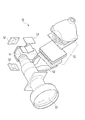
また、図4に示すプロジェクタ40に示されるように、色分離部及び色合成部として四角柱状のクロスダイクロイックプリズム(以下、XDP)41が設けられている。XDP41は、色分離作用を行う部分と色合成作用を行う部分とが鉛直方向に配置されている。3枚の反射型液晶パネル42は、XDP41の側面に対して傾斜して配置されている。照明光学系43は、投映レンズ44の下に配置され、XDP41に対して照明用の光束を斜め方向から入射させている。照明光学系43は、プロジェクタ40が鉛直方向に寸法が大きくならないようにミラー45を用いてその光軸が曲げられている。しかしながら、照明光学系43は投映レンズ44の下側に配置されているため、プロジェクタが垂直方向に大型化してしまっており、オンアクシス方式のプロジェクタと比べて光学部品を省略したことによる小型化が十分に実現されていない。
Further, as shown in the
本発明は、上記背景を考慮してなされたもので、投映レンズに要求されるバックフォーカスを小さくすることができ、オフアクシス方式を用いることによる低コスト化とコンパクト化を両立させたプロジェクタを提供することを目的とする。 The present invention has been made in consideration of the above-mentioned background, and can provide a projector that can reduce the back focus required for a projection lens and achieves both low cost and compactness by using an off-axis method. The purpose is to do.
上記目的を達成するために、本発明のプロジェクタは、照明光源から発せられた光束を色分離する色分離部と色分離された光束を合成する色合成部と、前記色分離部によって色分離された各光束に画像情報を付与し、前記色合成部に向かって反射させる複数の画像表示素子とを備え、前記色分離部によって色分離された光束が前記画像表示素子に入射する方向と、前記画像表示素子を反射した光束が前記色合成部に入射する方向とが異なるオフアクシス方式のプロジェクタにおいて、前記色分離部及び色合成部は、波長選択性の異なるダイクロイック膜が十字状に配列するように複数のプリズムブロック又はプレートが組み合わされたクロスダイクロイックプリズム又はクロスダイクロイックプレートから構成され、前記ダイクロイック膜の交わる交線が前記画像表示素子の長方形状の画面の短辺に対して垂直、かつ設置される際の水平方向に平行に設けられていることを特徴とする。 In order to achieve the above object, a projector according to the present invention is color-separated by a color separation unit that color-separates a light beam emitted from an illumination light source, a color synthesis unit that synthesizes the color-separated light beam, and the color separation unit. A plurality of image display elements that provide image information to each light beam and reflect the image information toward the color combining unit, and a direction in which the light beam color-separated by the color separation unit is incident on the image display device, In an off-axis projector in which the light beam reflected from the image display element is incident on the color synthesis unit, the color separation unit and the color synthesis unit are arranged such that dichroic films having different wavelength selectivity are arranged in a cross shape. A cross dichroic prism or a cross dichroic plate in which a plurality of prism blocks or plates are combined, and the dichroic film Wherein the Waru intersection line is provided in parallel to the horizontal direction when the vertical, and is placed against the short sides of the rectangular screen of the image display device.
また、前記色分離部及び色合成部は、1つのクロスダイクロイックプリズム又はクロスダイクロイックプレートからなることを特徴とする。 The color separation unit and the color synthesis unit may be formed of one cross dichroic prism or cross dichroic plate.
本発明によれば、色分離部及び色合成部のダイクロイック膜の交線に対して画像表示素子の長方形状の画面の短辺と垂直となるように画像表示素子を配置しているので、クロスダイクロイックプリズムの底面の一辺、又はクロスダイクロイックプレートの幅が小さくなり、画像表示素子と投映レンズの間の距離を小さくできる。すなわち、投映レンズに要求されるバックフォーカスが小さくでき、コンパクトな投映レンズを設計するために有利な条件が得られる。また、ダイクロイック膜の交線が水平方向と平行になるようにクロスダイクロイックプリズム又はクロスダイクロイックプレートを配置しているから、投映レンズと照明光学系を水平方向に並べて鉛直方向の寸法を小さくでき、水平方向に長い長方形のスクリーンを用いるのに好適なプロジェクタが得られる。 According to the present invention, the image display element is arranged so as to be perpendicular to the short side of the rectangular screen of the image display element with respect to the intersecting line of the dichroic film of the color separation unit and the color synthesis unit. One side of the bottom surface of the dichroic prism or the width of the cross dichroic plate is reduced, and the distance between the image display element and the projection lens can be reduced. That is, the back focus required for the projection lens can be reduced, and advantageous conditions can be obtained for designing a compact projection lens. In addition, since the cross dichroic prism or cross dichroic plate is arranged so that the intersecting line of the dichroic film is parallel to the horizontal direction, the projection lens and the illumination optical system can be arranged in the horizontal direction to reduce the vertical dimension. A projector suitable for using a rectangular screen having a long direction can be obtained.
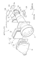
図1において、プロジェクタ10は、投映レンズ11と、三枚の反射型液晶パネル12R,12G,12Bと、XDP13、照明ランプ14、照明光学系15を備えている。照明光学系15は、第1レンズアレイ18,第2レンズアレイ19、PBSアレイ20、重ね合わせレンズ21からなる偏光変換インテグレータ光学系として構成されている。第1及び第2レンズアレイ18,19は、液晶パネル12R〜12Bの液晶画面の形状と相似形状のマイクロレンズがマトリクス状に配列されている。各マイクロレンズによって照明ランプ14から放射される照明光束が多数の光束に分割され、分割された光束ごとにPBSアレイ20上で微小な光源像を結像させる。
In FIG. 1, the projector 10 includes a
PBSアレイ20は、周知のように偏光反射膜と全反射膜とが交互に形成されたプリズムの集合体からなり、照明ランプ14から放射されるランダム偏光を、例えばS偏光に効率よく変換する。PBSアレイ20上で光源像を形成する各光束は、重ね合わせレンズ21により液晶パネル12R〜12Bのそれぞれの液晶画面12a上で重ね合わされ、各液晶パネルをその中央部から周辺部に亘って均一に照明する。
As is well known, the
照明光学系15から出射された白色の照明光束は、XDP13の側面に対して斜めに入射し、赤色光(R光)、緑色光(G光)、青色光(B光)に分離される。XDP13は、4つの直角プリズムブロックからなり、直角の頂角をもつ稜線を互いに向かい合わせにして接合した直方体形状のプリズムである。直角プリズムの接合面は、R光のみを反射する赤色反射面13aとB光のみを反射する青色反射面13bとを構成する2種類のダイクロイック膜が互いに直交するように十字状に設けられている。XDP13の側面には、偏光板23,24が設けられている。XDP13によって分離された各色の光束は、偏光板23を透過してその偏光度がさらに高められ、液晶パネル12R〜12Bに入射する。
The white illumination light beam emitted from the illumination
液晶パネル12R〜12Bは、入射した各色の照明光束を画像情報を有する画像光束に変調する。各色の画像光束はXDP13に向けて反射され、検光子として作用する偏光板24をそれぞれ透過して、XDP13に入射する。各色の画像光束はXDP13によって合成され、投映レンズ11に向かって出射される。なお、投映レンズ11は、複数枚のレンズで構成され、そのうちの一部のレンズが光軸に対してシフトしており、各液晶パネルが光軸A2に対して傾斜して設けられることにより発生する投映画像の歪みを補正している。
The
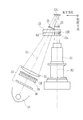
図2において、プロジェクタ10は、照明光学系15の光軸A1が投映レンズ11の光軸A2に対して略V字をなすオフアクシス式の光学系が形成されており、液晶パネル12R〜12Bは、液晶画面12aの法線が投映レンズ11の光軸A1と一致せず、XDP13の側面に対して傾斜して配置されている。液晶パネル12R〜12Bは、XDP13の各側面から一定距離の位置に設けられており、アスペクト比が例えば4対3の長方形状をした液晶画面12aの短辺S1がXDP13のダイクロイック膜の交線A3と垂直をなすように配置されている。投映レンズ11と照明光学系15は水平方向に沿って並んで配置され、その光軸A1,A2を通る平面がスクリーンの水平方向と平行になる。液晶パネル12R及び12Bは、XDP13の鉛直上方と鉛直下方にそれぞれ設けられており、プロジェクタ10は、その高さ寸法が液晶パネル12Rと12Bの間の距離とほぼ等しい大きさとなる。
In FIG. 2, the projector 10 is formed with an off-axis optical system in which the optical axis A1 of the illumination
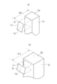
図3において、各液晶パネルは、液晶画面12aの短辺S1が交線A3と垂直をなすように、すなわち短辺S1がXDP13の底面13cと平行になるように配置されているため、XDP13に必要とされる底面13cの一辺は短辺S1の長さに応じた長さとなる(図3(a))。一方、各液晶パネルの長辺L1と平行な底面25cを有するXDP25を用いる場合、底面25cの一辺の長さは、液晶画面12aの長辺L1の長さに応じたものとなり(図3(b))、XDP13はXDP25に比べて底面積が小さくなる。したがって、両形態における液晶パネルから投映レンズ11までの距離、すなわち、XDP13を用いた場合に投映レンズ11に必要とされるバックフォーカスの大きさBf1と、XDP25を用いた場合に必要とされるバックフォーカスの大きさBf2とでは、プリズム底面の一辺の長さの差分だけBf1はBf2に比べて小さくなる。図3(a),(b)におけるXDP13、XDP25から液晶画面12aまでの距離はそれぞれ同じであり、XDP13を備えたプロジェクタ10は、光軸A2の方向の寸法が小さくなる。
In FIG. 3, each liquid crystal panel is arranged so that the short side S1 of the
なお、本発明においては、上記実施形態のように画像表示素子として液晶パネルを用いることに限らず、他のライトバルブや、デジタルマイクロミラーデバイス等のライトスイッチを用いた反射型プロジェクタとして構成したものであれば、同様の効果が得られる。また、色分離部、色合成部として用いられる光学部材として、クロスダイクロイックプリズムに限らず、ダイクロイック膜が形成されたガラス板を十字状に組み合わせたクロスダイクロイックプレートを用いてもよい。また、色合成部と色分離部を1つのクロスダイクロイックプリズム又はクロスダイクロイックプレートで構成することに限らず、色合成部と色分離部がそれぞれ分離された光学部材から構成されていてもよい。 The present invention is not limited to using a liquid crystal panel as an image display element as in the above-described embodiment, but is configured as a reflective projector using a light switch such as another light valve or a digital micromirror device. If so, the same effect can be obtained. Further, the optical member used as the color separation unit and the color synthesis unit is not limited to the cross dichroic prism, and a cross dichroic plate in which glass plates on which dichroic films are formed may be combined in a cross shape may be used. In addition, the color synthesis unit and the color separation unit are not limited to being configured by one cross dichroic prism or cross dichroic plate, but may be configured by optical members in which the color synthesis unit and the color separation unit are separated from each other.
10,40 プロジェクタ
11 投映レンズ
12R,12G,12B,42 液晶パネル
12a 液晶画面
13,25,41 クロスダイクロイックプリズム(XDP)
15 照明光学系
A3 交線
S1 短辺
L1 長辺
10, 40
15 Illumination optical system A3 Intersection line S1 Short side L1 Long side
Claims (2)
前記色分離部によって色分離された光束が前記画像表示素子に入射する方向と、前記画像表示素子を反射した光束が前記色合成部に入射する方向とが異なるオフアクシス方式のプロジェクタにおいて、
前記色分離部及び色合成部は、波長選択性の異なるダイクロイック膜が十字状に配列するように複数のプリズムブロック又はプレートが組み合わされたクロスダイクロイックプリズム又はクロスダイクロイックプレートから構成され、前記ダイクロイック膜の交わる交線が前記画像表示素子の長方形状の画面の短辺に対して垂直、かつ装置を設置する際の水平方向に平行に設けられていることを特徴とするプロジェクタ。 A color separation unit for color-separating a light beam emitted from an illumination light source; a color synthesis unit for synthesizing the color-separated light beam; and image information added to each light beam color-separated by the color separation unit, and the color synthesis unit A plurality of image display elements that reflect toward the
In the off-axis projector in which the direction in which the light beam color-separated by the color separation unit is incident on the image display element and the direction in which the light beam reflected by the image display element is incident on the color synthesis unit are different,
The color separation unit and the color synthesis unit are configured by a cross dichroic prism or a cross dichroic plate in which a plurality of prism blocks or plates are combined so that dichroic films having different wavelength selectivity are arranged in a cross shape. A projector in which intersecting lines are provided perpendicular to the short side of the rectangular screen of the image display element and parallel to the horizontal direction when the apparatus is installed.
Priority Applications (3)
| Application Number | Priority Date | Filing Date | Title |
|---|---|---|---|
| JP2004105508A JP2005292360A (en) | 2004-03-31 | 2004-03-31 | Projector |
| CNA2005100558856A CN1677219A (en) | 2004-03-31 | 2005-03-17 | Projector |
| US11/083,980 US20050231811A1 (en) | 2004-03-31 | 2005-03-21 | Projector |
Applications Claiming Priority (1)
| Application Number | Priority Date | Filing Date | Title |
|---|---|---|---|
| JP2004105508A JP2005292360A (en) | 2004-03-31 | 2004-03-31 | Projector |
Publications (1)
| Publication Number | Publication Date |
|---|---|
| JP2005292360A true JP2005292360A (en) | 2005-10-20 |
Family
ID=35049810
Family Applications (1)
| Application Number | Title | Priority Date | Filing Date |
|---|---|---|---|
| JP2004105508A Pending JP2005292360A (en) | 2004-03-31 | 2004-03-31 | Projector |
Country Status (3)
| Country | Link |
|---|---|
| US (1) | US20050231811A1 (en) |
| JP (1) | JP2005292360A (en) |
| CN (1) | CN1677219A (en) |
Cited By (1)
| Publication number | Priority date | Publication date | Assignee | Title |
|---|---|---|---|---|
| CN101995751A (en) * | 2009-08-20 | 2011-03-30 | 佳能株式会社 | Illumination optical system and projection display apparatus |
Families Citing this family (1)
| Publication number | Priority date | Publication date | Assignee | Title |
|---|---|---|---|---|
| CN104749869A (en) * | 2015-04-01 | 2015-07-01 | 苏州佳世达光电有限公司 | Projector |
Family Cites Families (7)
| Publication number | Priority date | Publication date | Assignee | Title |
|---|---|---|---|---|
| US6113239A (en) * | 1998-09-04 | 2000-09-05 | Sharp Laboratories Of America, Inc. | Projection display system for reflective light valves |
| US6398364B1 (en) * | 1999-10-06 | 2002-06-04 | Optical Coating Laboratory, Inc. | Off-axis image projection display system |
| US6698896B2 (en) * | 2001-01-19 | 2004-03-02 | Victor Company Of Japan, Ltd. | Color-separating and -recombining optical system and projection display using the same |
| US6618202B2 (en) * | 2001-05-29 | 2003-09-09 | Aurora Systems, Inc. | Projection system with an offset lens array to reduce vertical banding |
| US6909556B2 (en) * | 2002-01-14 | 2005-06-21 | Lightmaster Systems, Inc. | Design of prism assemblies and kernel configurations for use in projection systems |
| EP1523857A1 (en) * | 2002-07-19 | 2005-04-20 | Fuji Photo Film Co. Ltd. | Liquid crystal projector, liquid crystal device and substrate for liquid crystal device |
| JP2004085724A (en) * | 2002-08-23 | 2004-03-18 | Fuji Photo Optical Co Ltd | Image synthesizing optical device |
-
2004
- 2004-03-31 JP JP2004105508A patent/JP2005292360A/en active Pending
-
2005
- 2005-03-17 CN CNA2005100558856A patent/CN1677219A/en active Pending
- 2005-03-21 US US11/083,980 patent/US20050231811A1/en not_active Abandoned
Cited By (2)
| Publication number | Priority date | Publication date | Assignee | Title |
|---|---|---|---|---|
| CN101995751A (en) * | 2009-08-20 | 2011-03-30 | 佳能株式会社 | Illumination optical system and projection display apparatus |
| CN101995751B (en) * | 2009-08-20 | 2013-03-13 | 佳能株式会社 | Illumination optical system and projection display apparatus |
Also Published As
| Publication number | Publication date |
|---|---|
| CN1677219A (en) | 2005-10-05 |
| US20050231811A1 (en) | 2005-10-20 |
Similar Documents
| Publication | Publication Date | Title |
|---|---|---|
| JP5350610B2 (en) | Optical system for projector and corresponding projector | |
| US6905211B2 (en) | Color separation device, imaging optical engine, and projection apparatus | |
| JP5360683B2 (en) | projector | |
| KR100646285B1 (en) | Light source device used for projection type image display device using the reflection type image projecting device | |
| US6860607B2 (en) | Integrator type illumination optical system and projector having the same | |
| JP3858723B2 (en) | Optical unit and projection type projector device using the same | |
| JP2002182307A (en) | Projection type display device | |
| JPS6339294A (en) | Video projection equipment | |
| JP4539319B2 (en) | Projection display | |
| CN102498436B (en) | Nation device and projection type display device using the same | |
| JP2004286767A (en) | Projection display device | |
| JP3365618B2 (en) | Projector device | |
| JP2005292360A (en) | Projector | |
| JP2003075769A (en) | Optical unit and image display device using the same | |
| JP2006337791A (en) | Projection-type image display device, optical unit used therefor, and polarization separation member | |
| JP2007025287A (en) | Projector device and DMD element | |
| JP2001051347A (en) | Rear projection type display device | |
| JP4115420B2 (en) | Illumination device and projection display device | |
| JP2002196118A (en) | Optical element and projector | |
| JP4158789B2 (en) | projector | |
| JP2006113469A (en) | projector | |
| JP2005221980A (en) | projector | |
| JP2008170714A (en) | Lighting optical system and projection type display apparatus | |
| JP2018081325A (en) | Projection type display unit | |
| JP5104338B2 (en) | projector |