EP0984537A1 - Quick mounting system for an electrical apparatus by snapping on a DIN rail - Google Patents
Quick mounting system for an electrical apparatus by snapping on a DIN rail Download PDFInfo
- Publication number
- EP0984537A1 EP0984537A1 EP99113762A EP99113762A EP0984537A1 EP 0984537 A1 EP0984537 A1 EP 0984537A1 EP 99113762 A EP99113762 A EP 99113762A EP 99113762 A EP99113762 A EP 99113762A EP 0984537 A1 EP0984537 A1 EP 0984537A1
- Authority
- EP
- European Patent Office
- Prior art keywords
- nose
- installation device
- slide
- hat rail
- installation
- Prior art date
- Legal status (The legal status is an assumption and is not a legal conclusion. Google has not performed a legal analysis and makes no representation as to the accuracy of the status listed.)
- Granted
Links
Images


Classifications
-
- H—ELECTRICITY
- H02—GENERATION; CONVERSION OR DISTRIBUTION OF ELECTRIC POWER
- H02B—BOARDS, SUBSTATIONS OR SWITCHING ARRANGEMENTS FOR THE SUPPLY OR DISTRIBUTION OF ELECTRIC POWER
- H02B1/00—Frameworks, boards, panels, desks, casings; Details of substations or switching arrangements
- H02B1/015—Boards, panels, desks; Parts thereof or accessories therefor
- H02B1/04—Mounting thereon of switches or of other devices in general, the switch or device having, or being without, casing
- H02B1/052—Mounting on rails
- H02B1/0523—Mounting on rails locked into position by a sliding member
Definitions
- the invention relates to a quick fastening device according to the preamble of Claim 1.
- the fixture has a recess on its mounting surface for fixation or depression that has a fixed nose and a movable nose, the movable nose resiliently inside the recess on the fixed Nose is pressed too.
- the fixed one is used to fix the installation device Hooked in behind an edge of the top-hat rail and then the installation device by swiveling around this edge and pressing in the installation device locked onto the top-hat rail, the movable nose of the other edge of the top-hat rail is resiliently moved; after snapping on presses the spring against the top-hat rail and holds the installation device on it Way tight.
- the spring can be a helical compression spring; there are spring arrangements, where a wire spring is provided with which the slide against the top-hat rail is pressed.
- the object of the invention is a quick fastening device of the aforementioned Type to create, with a disassembly and assembly of the installation device with existing cross-wiring is also possible without tools, whereby safe and easy handling of the quick attachment is made possible.
- the slider consisting of resilient material is intended to be two parallel ones Outer arms with outer lugs projecting perpendicular to the slide and one resilient intermediate arm in between with a likewise perpendicular to the Have slider projecting intermediate nose, the nose surface in the relaxed State of the plane spanned by the outer arms is less Distance takes up as the nose surfaces of the outer lugs, so that the intermediate lug in assembled state the bracket on the top-hat rail takes over.
- the resilient Lifting the intermediate nose allows up to the nose surfaces of the two outer noses, whereby the disassembly by moving the installation device without Tool is made possible.
- Each groove can have two depressions, so that the slide in two positions is fixed, namely the snap-lock position and the position in which the slider is pulled out so far that the installation device can be lifted off is also possible with built-in cross wiring using busbars.
- the distance between the nose surfaces the outer arms of the hat rail should be dimensioned so that the outside the recess of the floor area of the installation housing free from the Top hat rail comes when the installation device comes from the top hat rail raised on the slide side and around the top-hat rail edge on the other, fixed nose is pivoted.
- the assembly of the arrangement is exactly the opposite: you push the fully pulled out Slider between the cross wiring and the top-hat rail and pivots the installation device with the floor surface or mounting surface parallel to the top-hat rail level and moves the installation device against the Cross wiring so that the slide is moved to the inner first position.
- Fig. 1 shows a slide 10 in perspective, which is in an installation device is used in the manner shown below.
- the slide has one Base plate 11, in which slots 12 and 13 are provided, whereby three side by side lying resilient arms are formed, namely two outer arms 14 and 15 and one Inner or intermediate arm 16.
- knobs 17 are provided (the knobs provided on the outer arm 15 are not visible).
- Perpendicular to the plane of the base plate 11 are on the outer arms 14 and 15 molded outer noses 18 and 19, each having a nose surface 20 and 21.
- an intermediate nose 23 is formed, the nose surface of which Reference number 24 has.
- the nose surfaces 20, 21 and 24 run parallel to the base plate or parallel to the arms 14, 15 and 16 and, as can be seen in more detail in FIG. 2 is spaced apart when the arms 14, 15 and 16 are relaxed Position.
- the nose surfaces 20 and 21 of the outer noses one Distance d from the surface of the bent surface facing the nose surfaces 20/21 Have leg 34 of the hat profile mounting rail; the nose surface 24 of the intermediate nose 23, which is still just visible, lies on the adjacent surface of the leg 34 on.
- the intermediate lug 23 is the actual movable lug, which with the fixed nose 32 cooperates.
- a sawtooth-like projection 38 integrally formed, which engages in a depression 39, so that the sawtooth Projection when the slide 10 moves from the top-hat rail 33 being held away; for mounting the slide 10 but easily in the two-sided Grooves 35 can be inserted, which is due to the inclined surface 40 on the projection 38th and is facilitated by corresponding deepening grooves or insertion grooves 41.
- the installation device 30 is connected to a cross wiring 50, which is an insulation housing 51 comprising chambers 52, with a busbar in one of the chambers 52 53 is used, on which a connecting lug 54 is formed, which in a Terminal opening not shown used on the installation switching device 30 and is stuck in it.
- Fig. 3 shows how the projection 38 in the recess 39 is held in which the perpendicular surface of the projection 38 strikes against the end wall 55 of the depression 39.
- the Installation switching device 30 has been raised in the area of the slide, so that the intermediate nose 23 has bent and the intermediate nose surface 24 due to the Leg 34 is aligned with the outer nose surfaces 20 and 21.
- a housing projection provided on both sides of the slide 56 integrally formed in the mounting position shown in FIG. 2 when moving the Installation device against the free longitudinal edge of the leg 34 of the top-hat rail 33 strikes, so that unintentional disassembly of the installation switching device is avoided.
- the installation device 30 only has to be raised, until the adjacent edge of the top-hat rail 33 is free of the projection 56. After that, the installation device 30 only needs to be moved (in the illustration 2 and 2 to the right), and the installation device 30 can be dismantled become.
- the quick fastening can also be released easily and without tools, so that the installation device 70 can be removed easily and without tools.
- the slider 10 is provided on the installation device, on which the sawtooth-like projection 38 is formed. In the state in which the installation device 70 is snapped onto the top-hat rail 33 and the slider 10 is pressed against the edge 34 of the top-hat rail 33 due to the spring action (see above), the distance of the sawtooth-like projection 38 from the wall 55 of the recess is 39 the size b.
- the fixed nose 71 there is between the end of the fixed nose 71, which cooperates with the movable nose 23, and the bottom 72 of the recess (without reference number), which is formed by the fixed nose 71, into which the edge 34a opposite the edge 34 is then mounted State intervenes, the distance t. In other words: in this case, the fixed nose 71 overlaps the edge 34a by the amount t.
- the distance with the value b is greater than the distance with the value t, so that when the installation device 70 is moved in the direction of arrow P 1 on the top-hat rail 33 and the projection 38 bears against the wall 55, the fixed nose 71 is free of the edge 34a, whereby a distance t 1 is created between the edge 34 a and the fixed nose 71, so that the installation device 70 can be pivoted counterclockwise P 4 around the edge 34 in the region of the movable nose 23, which is shown in FIG. 8 can be seen. If the fixed nose 71 has now been released from the edge 34a, that is to say the nose 71 is located above the edge 34a, then the installation device 70 can be disassembled by moving the installation device 70 in the direction of the arrow P 3 .
- a tool can also be used which pushes the slide 10 downwards presses so that the sawtooth-like projection 38 come out of the recess 39 can.
Abstract
Description
Die Erfindung betrifft eine Schnellbefestigungsvorrichtung nach dem Oberbegriff des
Anspruches 1.The invention relates to a quick fastening device according to the preamble of
In einer elektrischen Anlage, beispielsweise in einer Hausinstallationsanlage, werden elektrische Installationsgeräte auf Tragschienen befestigt, die ein Hutprofil besitzen. Zur Fixierung besitzt das Installationsgerät an seiner Befestigungsfläche eine Ausnehmung oder Vertiefung, die eine feststehende Nase und eine bewegbare Nase aufweist, wobei die bewegbare Nase federnd ins Innere der Ausnehmung auf die feststehende Nase zu gedrückt ist. Zur Fixierung des Installationsgerätes wird die feststehende Nase hinter eine Kante der Hutprofiltragschiene eingehängt und dann das Installationsgerät durch Verschwenken um diese Kante und Eindrücken des Installationsgerätes auf die Hutprofiltragschiene verrastet, wobei die bewegbare Nase von der anderen Kante der Hutprofiltragschiene federnd verschoben wird; nach dem Aufrasten drückt die Feder gegen die Hutprofilschiene und hält das Installationsgerät auf diese Weise fest. In an electrical system, for example in a house installation system electrical installation devices attached to mounting rails that have a hat profile. The fixture has a recess on its mounting surface for fixation or depression that has a fixed nose and a movable nose, the movable nose resiliently inside the recess on the fixed Nose is pressed too. The fixed one is used to fix the installation device Hooked in behind an edge of the top-hat rail and then the installation device by swiveling around this edge and pressing in the installation device locked onto the top-hat rail, the movable nose of the other edge of the top-hat rail is resiliently moved; after snapping on presses the spring against the top-hat rail and holds the installation device on it Way tight.
Es gibt eine große Vielzahl von Schnellbefestigungsvorrichtungen; bei den meisten ist die bewegbare Nase an einem Schieber angeformt, der senkrecht zur Hutprofilschiene von einer Feder nach innen in die Ausnehmung gedrückt ist. Wenn der Schieber aus Metall besteht, dann kann die Feder eine Schraubendruckfeder sein; es gibt Federanordnungen, bei denen eine Drahtbiegefeder vorgesehen ist, mit der der Schieber gegen die Hutprofiltragschiene gedrückt wird.There are a wide variety of quick fasteners; is with most the movable nose is formed on a slide that is perpendicular to the top-hat rail is pressed into the recess by a spring. When the slider is off Metal, the spring can be a helical compression spring; there are spring arrangements, where a wire spring is provided with which the slide against the top-hat rail is pressed.
Wenn auf der Zugangsseite der Installationsgeräte, beispielsweise der Leitungsschutzschalter, eine sog. Querverdrahtung in Form einer Sammelschiene oder in Form von mehrphasigen Sammelschienenblocks angeschlossen ist, dann besteht das Problem, daß bei den meisten bekannten Schnellbefestigungsvorrichtungen für die Demontage eines Installationsgerätes innerhalb einer Installationsanlage die Querverdrahtung entfernt werden muß. Zu diesem Zwecke sind Schieber bekannt geworden, die ein Verschieben des Installationsgerätes auf der Hutprofiltragschiene gestatten, soweit, daß das Installationsgerät von der Anschlußfahne an der Querverdrahtung bzw. der Sammelschiene freikommt und senkrecht zur Hutprofilschiene abgehoben werden kann.If on the access side of the installation devices, for example the circuit breaker, a so-called cross wiring in the form of a busbar or in the form of multi-phase busbar blocks, then there is the problem that with most known quick fasteners for disassembly of an installation device within an installation system, the cross-wiring must be removed. Sliders have become known for this purpose, that allow the installation device to be moved on the top-hat rail, to the extent that the installation device is removed from the connection lug on the cross-wiring or the busbar is released and lifted perpendicular to the top-hat rail can.
Aufgabe der Erfindung ist es, eine Schnellbefestigungsvorrichtung der eingangs genannten Art zu schaffen, bei der eine Demontage und eine Montage des Installationsgerätes bei vorhandener Querverdrahtung auch ohne Werkzeuge ermöglicht ist, wobei eine sichere und einfache Handhabung der Schnellbefestigung ermöglicht ist.The object of the invention is a quick fastening device of the aforementioned Type to create, with a disassembly and assembly of the installation device with existing cross-wiring is also possible without tools, whereby safe and easy handling of the quick attachment is made possible.
Diese Aufgabe wird erfindungsgemäß gelöst durch die Merkmale des Anspruches 1.This object is achieved according to the invention by the features of
Erfindungsgemäß also soll der aus federndem Material bestehende Schieber zwei parallele Außenarme mit senkrecht zum Schieber vorspringenden Außennasen und einen dazwischen liegenden, federnden Zwischenarm mit einer ebenfalls senkrecht zum Schieber vorspringenden Zwischennase aufweisen, dessen Nasenfläche im entspannten Zustand von der durch die Außenarme aufgespannten Ebene einen geringeren Abstand als die Nasenflächen der Außennasen einnimmt, so daß die Zwischennase im montierten Zustand die Halterung an der Hutprofilschiene übernimmt. According to the invention, the slider consisting of resilient material is intended to be two parallel ones Outer arms with outer lugs projecting perpendicular to the slide and one resilient intermediate arm in between with a likewise perpendicular to the Have slider projecting intermediate nose, the nose surface in the relaxed State of the plane spanned by the outer arms is less Distance takes up as the nose surfaces of the outer lugs, so that the intermediate lug in assembled state the bracket on the top-hat rail takes over.
Damit ist zur Demontage ein Anheben des Installationsgerätes möglich, wobei die federnde Zwischennase ein Anheben gestattet bis zu den Nasenflächen der beiden Außennasen, wodurch die Demontage durch Verschieben des Installationsgerätes ohne Werkzeug ermöglicht wird.This allows the installation device to be lifted for disassembly, the resilient Lifting the intermediate nose allows up to the nose surfaces of the two outer noses, whereby the disassembly by moving the installation device without Tool is made possible.
Damit der Schieber bzw. das Installationsgerät bezogen auf den Schieber in zwei unterschiedlichen Stellungen verrastbar ist, sind an den Außenkanten der Außenarme senkrecht dazu in entgegengesetzte Richtung vorspringende Noppen vorgesehen, die in entsprechende Vertiefungen an den Schieber führender Rillen eingreifen.So that the slide or the installation device related to the slide in two different Positions can be locked are on the outer edges of the outer arms Knobs protruding perpendicularly in the opposite direction are provided engage in corresponding recesses on the slide of leading grooves.
Dabei kann jede Rille zwei Vertiefungen aufweisen, so daß der Schieber in zwei Stellungen fixiert ist, nämlich der Aufschnapp-Verrastungsstellung und der Stellung, in der der Schieber soweit nach außen gezogen ist, daß ein Abheben des Installationsgerätes auch bei eingebauter Querverdrahtung mittels Sammelschienen ermöglicht ist.Each groove can have two depressions, so that the slide in two positions is fixed, namely the snap-lock position and the position in which the slider is pulled out so far that the installation device can be lifted off is also possible with built-in cross wiring using busbars.
Gemäß einer weiteren Ausgestaltung der Erfindung kann an der dem Installationsgehäuseboden zugewandten Ende eine sägezahnartige Nase angeformt sein, die in eine Einsenkung am Gehäuseboden eingreift. Diese verhindert eine versehentliche Demontage des Schaltgerätes und ein versehentliches Herausziehen des Schiebers aus der inneren in die äußere Stellung.According to a further embodiment of the invention, the bottom of the installation housing end facing a sawtooth-shaped nose, which is in a Countersink on the housing base engages. This prevents accidental disassembly of the switching device and an accidental pulling out of the slide from the inner to outer position.
Gemäß einer weiteren Ausgestaltung der Erfindung kann der Abstand der Nasenflächen der Außenarme von der Hutprofiltragschiene so bemessen sein, daß die außerhalb der Ausnehmung befindliche Bodenfläche des Installationsgehäuses frei von der Hutprofiltragschiene kommt, wenn das Installationsgerät von der Hutprofiltragschiene auf der Schieberseite angehoben und um die Hutprofilschienenkante an der anderen, feststehenden Nase geschwenkt wird.According to a further embodiment of the invention, the distance between the nose surfaces the outer arms of the hat rail should be dimensioned so that the outside the recess of the floor area of the installation housing free from the Top hat rail comes when the installation device comes from the top hat rail raised on the slide side and around the top-hat rail edge on the other, fixed nose is pivoted.
Dadurch ist es möglich, mittels der Hutprofiltragschiene den Schieber so ortsfest zu halten, daß das Installationsgerät parallel zu der Hutprofilschienenebene und quer zur Hutprofiltragschiene verschoben werden kann, so daß die benachbarte Anschlußklemme, an der die Querverdrahtung angeschlossen ist, von den Anschlußfahnen der Querverdrahtung freikommt, so daß das Installationsgerät mit dem vollständig herausgezogenen Schieber, der sich hier in der zweiten äußeren Stellung befindet, aus dem Zwischenraum zwischen der Hutprofiltragschiene und der Querverdrahtung oder Sammelschiene oder dem Sammelschienenblock herausgezogen werden kann.This makes it possible to use the top-hat rail to slide the slider in place keep that the installation device parallel to the hat rail level and transverse to Top-hat rail can be moved so that the adjacent terminal, to which the cross wiring is connected, from the connection lugs of the Cross wiring is released, so that the installation device with the fully pulled out Slider, which is here in the second outer position, from the Space between the top-hat rail and the cross-wiring or busbar or the busbar block can be pulled out.
Die Montage der Anordnung verläuft genau umgekehrt: Man schiebt den ganz herausgezogenen Schieber zwischen die Querverdrahtung und die Hutprofiltragschiene und verschwenkt das Installationsgerät etwa mit der Bodenfläche oder Befestigungsfläche parallel zur Hutprofilschienenebene und verschiebt das Installationsgerät gegen die Querverdrahtung, so daß der Schieber in die innere erste Stellung verschoben wird.The assembly of the arrangement is exactly the opposite: you push the fully pulled out Slider between the cross wiring and the top-hat rail and pivots the installation device with the floor surface or mounting surface parallel to the top-hat rail level and moves the installation device against the Cross wiring so that the slide is moved to the inner first position.
Weitere Ausgestaltungen und Verbesserungen der Erfindung sind den weiteren Unteransprüchen zu entnehmen.Further refinements and improvements of the invention are the further subclaims refer to.
Anhand der Zeichnung, in der ein Ausführungsbeispiel der Erfindung dargestellt ist, sollen die Erfindung sowie weitere vorteilhafte Ausgestaltungen und Verbesserungen der Erfindung näher erläutert und beschrieben werden.Using the drawing, in which an embodiment of the invention is shown, the invention and further advantageous refinements and improvements the invention are explained and described in more detail.
Es zeigen:
- Fig. 1
- eine perspektivische Ansicht auf einen Schieber,
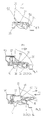
- Fig. 2 bis 5
- unterschiedliche Stellungen bei der Demontage eines Installationsgerätes mit vorhandener Querverdrahtung.
- Fig. 1
- a perspective view of a slide,
- 2 to 5
- Different positions when dismantling an installation device with existing cross-wiring.
Die Fig. 1 zeigt einen Schieber 10 in perspektivischer Darstellung, der in ein Installationsgerät
auf weiter unten dargestellte Weise eingesetzt wird. Der Schieber besitzt eine
Grundplatte 11, in der Schlitze 12 und 13 vorgesehen sind, wodurch drei nebeneinander
liegende federnde Arme gebildet sind, nämlich zwei Außenarme 14 und 15 und ein
Innen- oder Zwischenarm 16. An den Außenarmen 14 und 15, d. h. an den Längskanten,
sind Noppen 17 vorgesehen (die am Außenarm 15 vorgesehene Noppe ist nicht
sichtbar). Senkrecht zu der Ebene der Grundplatte 11 sind an den Außenarmen 14 und
15 Außennasen 18 und 19 angeformt, die jeweils eine Nasenfläche 20 und 21 besitzen.
Am Zwischenarm 16 ist eine Zwischennase 23 angeformt, deren Nasenfläche die
Bezugsziffer 24 besitzt. Die Nasenflächen 20, 21 und 24 verlaufen parallel zur Grundplatte
bzw. parallel zu den Armen 14, 15 und 16 und sind, wie aus Fig. 2 näher ersichtlich
ist, in Abstand zueinander angeordnet, wenn die Arme 14, 15 und 16 in entspannter
Stellung sind.Fig. 1 shows a
An dem den Nasen 18, 19 und 23 entgegengesetzten Ende der Grundplatte 11 sind
senkrecht zur Grundplatte in die gleiche Richtung wie die Nasen 18, 19, 23 vorspringende
Wandanformungen 25 und 26 vorgesehen, die mittels einer Verbindung 27
Verbindungssteg 27 verbunden sind, so daß hierdurch eine Öffnung 28 gebildet ist, in
die ein Werkzeug zum Verschieben des Schiebers am Installationsgerät einsteckbar
ist. Die im Bereich der Wandanformungen 25 und 26 befindliche Endkante 29 besitzt
von der Projektion der den Nasen zugewandten Kante der Verbindung 27 einen Abstand,
so daß in der Projektion, also in Pfeilrichtung P gesehen, zwischen der Verbindung
27 und der Endkante 29 ein Schlitz gebildet ist. Der Schieber 10 ist an der Bodenfläche
eines Installationsgerätes 30 angeordnet, welches eine Ausnehmung 31
aufweist, an deren einem Ende bzw. an deren einen Wand eine feststehende Nase 32
angeordnet ist. Der Schieber 10 bildet dann die sog. bewegliche Nase, wobei die bewegliche
Nase und die feststehende Nase hinter die Längskanten einer Hutprofiltragschiene
33 gerastet werden können.At the opposite end of the
Aus der Fig. 2 ist ersichtlich, daß die Nasenflächen 20 und 21 der Außennasen einen
Abstand d von der den Nasenflächen 20/21 zugewandten Fläche des umgebogenen
Schenkels 34 der Hutprofiltragschiene aufweisen; die Nasenfläche 24 der Zwischennase
23, die noch gerade sichtbar ist, legt sich auf die benachbarte Fläche des Schenkels
34 auf. Damit ist die Zwischennase 23 die eigentliche bewegbare Nase, die mit der
feststehenden Nase 32 zusammenwirkt.From Fig. 2 it can be seen that the
Die Längskanten der Basisplatte 11 des Schiebers 10 gleiten in Rillen 35 im Installationsgerät,
wobei die Noppen 17 in entsprechende Vertiefungen in den Rillen 35 hineinschnappen
können.The longitudinal edges of the
Aus der Fig. 1 ist ersichtlich, daß an die Außennasen 18 und 19 Verstärkungsrippen 36
und 37 anschließen, so daß die Arme 14 und 15 zwar aufeinanderzu gebogen werden
können, nicht aber aus der Grundplattenebene herausbiegbar sind. Da der Zwischenarm
16 eine derartige Verstärkungsrippe nicht besitzt, kann der Zwischenarm 16 leicht
auch aus der Ebene der Grundplatte 11 herausgebogen werden.From Fig. 1 it can be seen that on the
Auf der den Nasen abgewandten Fläche des Schiebers ist ein sägezahnartiger Vorsprung
38 angeformt, der in in eine Einsenkung 39 eingreift, so daß der sägezahnartige
Vorsprung bei einer Bewegung des Schiebers 10 von der Hutprofiltragschiene 33
weg festgehalten wird; zur Montage des Schiebers 10 aber leicht in die beidseitigen
Rillen 35 eingeschoben werden kann, was durch die Schrägfläche 40 am Vorsprung 38
sowie durch entsprechende Vertiefungsrillen bzw. Einführungsrillen 41 erleichtert wird.On the surface of the slide facing away from the lugs is a sawtooth-
Das Installationsgerät 30 ist an eine Querverdrahtung 50 angeschlossen, die ein Isolationsgehäuse
51 mit Kammern 52 umfaßt, wobei in eine der Kammern 52 eine Sammelschiene
53 eingesetzt ist, an der eine Anschlußfahne 54 angeformt ist, die in eine
nicht näher dargestellte Anschlußklemmenöffnung am Installationsschaltgerät 30 eingesetzt
und darin festgeklemmt ist. Die Fig. 3 zeigt, wie der Vorsprung 38 in der Vertiefung
39 festgehalten wird, in dem die senkrecht verlaufende Fläche des Vorsprunges
38 gegen die Endwand 55 der Einsenkung 39 anschlägt.The
Die Fig. 3 zeigt allerdings den Beginn der Demontage des Installationsgerätes. Das
Installationsschaltgerät 30 ist im Bereich des Schiebers angehoben worden, so daß
sich die Zwischennase 23 verbogen hat und die Zwischennasenfläche 24 aufgrund des
Schenkels 34 mit den Außennasenflächen 20 und 21 fluchtet. Am Boden des Installationsschaltgerätes
30 ist ein beidseitig zu dem Schieber vorgesehener Gehäusevorsprung
56 angeformt, der in der Montagestellung gemäß Fig. 2 beim Verschieben des
Installationsgerätes gegen die freie Längskante des Schenkels 34 der Hutprofilschiene
33 anschlägt, so daß eine unbeabsichtigte Demontage des Installationsschaltgerätes
vermieden wird.3, however, shows the beginning of the disassembly of the installation device. The
In der angehobenen Stellung, siehe Fig. 3, ist die freie Kante des Schenkels 34 frei von
dem Vorsprung 56, so daß das Installationsgerät 30 nach rechts in Pfeilrichtung P1
verschoben werden kann. Da der sägezahnartige Vorsprung 38 durch die Kante 55 der
Einsenkung 39 am Weiterschieben gehindert ist, muß das hintere Ende des Schiebers
10 nieder gehalten werden, so daß der Vorsprung 38 frei von der Wand 55 der Einsenkung
39 kommt. Zwecks Niederhaltung befindet sich am Gehäuse 50 der Querverdrahtung
eine Leiste 57, gegen die der Schieber 10 anschlägt, damit verbleibt der Schieber
10 der in Fig. 3 bzw. Fig. 4 gezeigten Stellung und das Installationsgerät kann nun in
Pfeilrichtung P1 weiter verschoben werden, bis der Schieber 10 praktisch vollständig
aus dem Installationsgerät herausgeschoben ist. Zwischen dem Ende der Anschlußfahne
54 und der Längskante des Schenkels 34 befindet sich ein Zwischenraum 60,
aus dem der Schieber 10 in Pfeilrichtung P2 herausgezogen werden kann, ohne daß
die Querverdrahtung mit dem Gehäuse 50 demontiert werden muß. In Fig. 5 erkennt
man die eine Rille 35 sowie eine Vertiefung 61, in der die Noppen 17 in der zweiten, in
Fig. 5 gezeigten Stellung einrasten können.In the raised position, see FIG. 3, the free edge of the
Zur Montage des Installationsschaltgerätes 30 geht man den umgekehrten Weg: man
schiebt den herausgezogenen Schieber 10 durch den Zwischenraum 60 bis hinter die
Leiste 57, schwenkt dann das Installationgsgerät 30 in Uhrzeigersinn, so daß die Nasen
20, 21, 24 hinter den Schenkel 34 schnappen können. Danach wird das Installationsgerät
in Pfeilrichtung P3 in die Stellung verschoben, die in der Fig. 2 dargestellt ist.To assemble the
Wenn der sägezahnartige Vorsprung 38 wegfällt, was bei einer weiteren Ausgestaltung
der Erfindung der Fall sein kann, dann muß das Installationsgerät nur angehoben werden,
bis die benachbarte Kante der Hutprofilschiene 33 frei von dem Vorsprung 56 ist.
Danach braucht das Installationsgerät 30 nur noch verschoben werden (in der Darstellung
gemäß Fig. 2 und 2 nach rechts), und das Installationsgerät 30 kann demontiert
werden.If the sawtooth-
Bei einer weiteren Ausgestaltung der Erfindung (siehe Fig. 6 bis 9) wird die Schnellbefestigung
auch dann einfach und ohne Werkzeug lösbar, so daß das Installationsgerät
70 einfach und ohne Werkzeug demontierbar ist. Am Installationsgerät ist der Schieber
10 vorgesehen, an dem der sägezahnartige Vorsprung 38 angeformt ist. In dem Zustand,
in dem das Installationsgerät 70 auf der Hutprofiltragschiene 33 aufgeschnappt
ist und der Schieber 10 aufgrund der Federwirkung (siehe weiter oben) gegen die
Kante 34 der Hutprofiltragschiene 33 angedrückt wird, beträgt der Abstand des sägezahnartigen
Vorsprunges 38 von der Wandung 55 der Vertiefung 39 die Größe b. Dabei
besteht zwischen dem Ende der feststehenden Nase 71, die mit der beweglichen
Nase 23 zusammenwirkt, und dem Grund 72 der Ausnehmung (ohne Bezugsziffer), die
durch die feststehende Nase 71 gebildet wird, in die dann die der Kante 34 gegenüberliegende
Kante 34a im montierten Zustand eingreift, der Abstand t. Mit anderen Worten:
in diesem Falle übergreift die feststehende Nase 71 die Kante 34a um den Betrag
t. Der Abstand mit dem Wert b ist größer als der Abstand mit dem Wert t, so daß dann,
wenn das Installationsgerät 70 in Pfeilrichtung P1 auf der Hutprofilschiene 33 verschoben
wird und der Vorsprung 38 gegen die Wandung 55 anliegt, die feststehende Nase
71 frei von der Kante 34a wird, wobei zwischen der Kante 34 a und der feststehenden
Nase 71 ein Abstand t1 entsteht, so daß das Installationsgerät 70 um die Kante 34 im
Bereich der bewegbaren Nase 23 entgegen dem Uhrzeiger P4 verschwenkt werden
kann, was in Fig. 8 zu sehen ist. Wenn nun die feststehende Nase 71 von der Kante
34a freigekommen ist, sich die Nase 71 also oberhalb der Kante 34a befindet, dann
kann eine Demontage des Installationsgerätes 70 durch Verschieben des Installationsgerätes
70 in Pfeilrichtung P3 erfolgen.In a further embodiment of the invention (see FIGS. 6 to 9), the quick fastening can also be released easily and without tools, so that the
Bei der in den Fig. 6 bis 9 dargestellten Demontageart wäre eine Querverdrahtung zu
demontieren, da das Verschieben in der letzten Phase in Pfeilrichtung P3 in Richtung
auf die Querverdrahtung erfolgen müßte. Andererseits wäre eine Demontage auch
dann leicht möglich, wenn mittels eines Werkzeuges durch Druck D auf den Schieber
10 der sägezahnartige Vorsprung 38 aus der Vertiefung 39 herausgehoben würde;
dann wäre der Schieber 10 soweit bezogen auf das Installationsgerät 70 verschiebbar,
daß eine Demontage möglich ist, ähnlich wie in der Ausführung gemäß den Fig. 2 bis
5.In the type of disassembly shown in FIGS. 6 to 9, cross-wiring would have to be dismantled, since the shifting in the last phase would have to take place in the direction of arrow P 3 in the direction of the cross-wiring. On the other hand, disassembly would also be easily possible if the sawtooth-
Nachzutragen ist noch, daß anstatt der Leiste 57 am Gehäuse 50 der Querverdrahtung
auch ein Werkzeug verwendet werden kann, welches den Schieber 10 nach unten
drückt, so daß der sägezahnartige Vorsprung 38 aus der Vertiefung 39 freikommen
kann.It should be added that instead of the
Claims (8)
Applications Claiming Priority (2)
| Application Number | Priority Date | Filing Date | Title |
|---|---|---|---|
| DE19836890 | 1998-08-14 | ||
| DE19836890A DE19836890A1 (en) | 1998-08-14 | 1998-08-14 | Rapid fixing device for electrical installation device e.g. fault current circuit breaker, has slider with 3 arms with normal protrusions, with only center protrusion holding onto bearer rail |
Publications (2)
| Publication Number | Publication Date |
|---|---|
| EP0984537A1 true EP0984537A1 (en) | 2000-03-08 |
| EP0984537B1 EP0984537B1 (en) | 2005-12-21 |
Family
ID=7877539
Family Applications (1)
| Application Number | Title | Priority Date | Filing Date |
|---|---|---|---|
| EP99113762A Expired - Lifetime EP0984537B1 (en) | 1998-08-14 | 1999-07-14 | Quick mounting system for an electrical apparatus by snapping on a DIN rail |
Country Status (3)
| Country | Link |
|---|---|
| EP (1) | EP0984537B1 (en) |
| AT (1) | ATE313866T1 (en) |
| DE (2) | DE19836890A1 (en) |
Cited By (1)
| Publication number | Priority date | Publication date | Assignee | Title |
|---|---|---|---|---|
| US7758368B2 (en) | 2007-05-29 | 2010-07-20 | Honeywell International Inc. | DIN rail mount |
Families Citing this family (8)
| Publication number | Priority date | Publication date | Assignee | Title |
|---|---|---|---|---|
| DE10002125A1 (en) * | 2000-01-20 | 2001-07-26 | Abb Patent Gmbh | Quick attachment for an electrical installation device |
| DE10220821B3 (en) * | 2002-05-10 | 2004-02-26 | Geyer Ag | Quick-fixing for serial electrical installation device, comprises one-piece snap-fit latch fitted to holder at base of electrical installation device for sliding to and from collector rail |
| WO2006069634A1 (en) | 2004-12-24 | 2006-07-06 | Abb Patent Gmbh | Quick-fixing device on electrical installation equipment |
| DE102004062524A1 (en) * | 2004-12-24 | 2006-07-06 | Abb Patent Gmbh | Quick fixing device on electronic installation equipment such as power breaker or RCD has fixed and sprung moving lugs and clips onto top hat rail |
| DE102005005380A1 (en) * | 2005-02-05 | 2006-08-10 | Abb Patent Gmbh | Electrical installation device e.g. line circuit breaker, for hat profile mounting rail, has lug made of plastic strip having strip sections fixed with one another by hinges, and formed as one piece in housing made of thermoplastic material |
| DE102009030055B4 (en) | 2009-06-22 | 2012-07-05 | Abb Ag | Quick-fastening device for an electrical service switching device |
| CN201821007U (en) | 2010-05-03 | 2011-05-04 | Abb股份公司 | Electrical installation switching device with fast fixture |
| DE202020101687U1 (en) | 2020-03-30 | 2021-07-01 | WAGO Verwaltungsgesellschaft mit beschränkter Haftung | Slide for mounting adapter and mounting adapter |
Citations (2)
| Publication number | Priority date | Publication date | Assignee | Title |
|---|---|---|---|---|
| EP0359677A1 (en) * | 1988-09-16 | 1990-03-21 | Merlin Gerin | Device to attach a modular electrical apparatus onto a profile support rail |
| EP0680114A1 (en) * | 1994-04-27 | 1995-11-02 | Bticino S.P.A. | A modular electric apparatus with rail hook-up device |
Family Cites Families (15)
| Publication number | Priority date | Publication date | Assignee | Title |
|---|---|---|---|---|
| DE7210870U (en) * | 1972-03-22 | 1972-06-22 | Kloeckner Moeller Gmbh | Fastening arrangement for electrical switchgear on mounting rails |
| DE7916477U1 (en) * | 1979-06-08 | 1980-11-20 | Licentia Patent-Verwaltungs-Gmbh, 6000 Frankfurt | Quick fastener |
| DE8020041U1 (en) * | 1980-07-25 | 1980-10-23 | Siemens Ag, 1000 Berlin Und 8000 Muenchen | Device for fastening electrical installation devices |
| US4671697A (en) * | 1984-05-09 | 1987-06-09 | Mitsubishi Denki Kabushiki Kaisha | Apparatus for mounting electrical appliance on frame |
| DE3426377A1 (en) * | 1984-07-18 | 1986-01-30 | Brown, Boveri & Cie Ag, 6800 Mannheim | QUICK FASTENING FOR FASTENING A HOUSING OF AN ELECTRICAL INSTALLATION DEVICE ON A HAT PROFILE RAIL |
| DE3513762A1 (en) * | 1985-04-17 | 1986-10-23 | Brown, Boveri & Cie Ag, 6800 Mannheim | Electrical insulation apparatus which can be latched onto a supporting rail |
| DE8518168U1 (en) * | 1985-06-22 | 1985-08-22 | Eberle GmbH, 8500 Nürnberg | Device for attaching a switching device to a U-shaped mounting rail |
| DE8704866U1 (en) * | 1987-04-01 | 1987-06-19 | Christian Geyer Gmbh & Co, 8500 Nuernberg, De | |
| JPH06859Y2 (en) * | 1988-12-13 | 1994-01-05 | オムロン株式会社 | Mounting device for electrical equipment |
| FR2662553B1 (en) * | 1990-05-28 | 1992-08-28 | Legrand Sa | ELECTRICAL APPARATUS TO BE RETAINED ON A SUPPORT BY SIMPLE LATCHING. |
| AT400500B (en) * | 1990-12-17 | 1996-01-25 | Schrack Components Ag | QUICK FASTENING DEVICE |
| DE9203072U1 (en) * | 1992-03-07 | 1992-06-17 | Elektroinstallation Annaberg Gmbh, O-9300 Annaberg-Buchholz, De | |
| DE4210556C2 (en) * | 1992-03-31 | 1994-11-24 | Schupa Elektro Gmbh & Co Kg | Device for fastening electrical installation devices on mounting rails |
| DE9406563U1 (en) * | 1994-04-20 | 1994-09-08 | Erich Grau Gmbh Stanzwerk Fuer | Device for holding electrical components |
| DE19606216C2 (en) * | 1996-02-20 | 2001-02-15 | Abb Patent Gmbh | Device for fastening a low-voltage device on a top-hat rail |
-
1998
- 1998-08-14 DE DE19836890A patent/DE19836890A1/en not_active Withdrawn
-
1999
- 1999-07-14 EP EP99113762A patent/EP0984537B1/en not_active Expired - Lifetime
- 1999-07-14 AT AT99113762T patent/ATE313866T1/en not_active IP Right Cessation
- 1999-07-14 DE DE59912952T patent/DE59912952D1/en not_active Expired - Lifetime
Patent Citations (2)
| Publication number | Priority date | Publication date | Assignee | Title |
|---|---|---|---|---|
| EP0359677A1 (en) * | 1988-09-16 | 1990-03-21 | Merlin Gerin | Device to attach a modular electrical apparatus onto a profile support rail |
| EP0680114A1 (en) * | 1994-04-27 | 1995-11-02 | Bticino S.P.A. | A modular electric apparatus with rail hook-up device |
Cited By (1)
| Publication number | Priority date | Publication date | Assignee | Title |
|---|---|---|---|---|
| US7758368B2 (en) | 2007-05-29 | 2010-07-20 | Honeywell International Inc. | DIN rail mount |
Also Published As
| Publication number | Publication date |
|---|---|
| EP0984537B1 (en) | 2005-12-21 |
| ATE313866T1 (en) | 2006-01-15 |
| DE59912952D1 (en) | 2006-01-26 |
| DE19836890A1 (en) | 2000-02-17 |
Similar Documents
| Publication | Publication Date | Title |
|---|---|---|
| EP2400611B1 (en) | Power distribution panel | |
| EP0010251B1 (en) | Device for the internal mounting of installation equipment | |
| DE102005060585A1 (en) | Electrical installation device | |
| EP0984537A1 (en) | Quick mounting system for an electrical apparatus by snapping on a DIN rail | |
| DE102010052956A1 (en) | Electrical service switching device with a quick-release device | |
| EP0271891A2 (en) | Cable supporting raceway for housing power and telecommunication cables | |
| DE102011101078B4 (en) | Electrical service switching device with a quick-release device | |
| DE10061940C2 (en) | Coupling plate for track adapter | |
| DE3149310A1 (en) | Device and method for attachment of electrical installation apparatuses on standard profiled rails, especially on cap profiled rails | |
| DE19524381C2 (en) | Installation duct with a metallic duct profile open to one side | |
| DE4011447C2 (en) | Device for snap fastening an electrical installation device | |
| EP0051755A1 (en) | Protective cover for terminals of electrical appliances | |
| DE3441890C2 (en) | ||
| DE4439672C2 (en) | Device for releasable quick fastening of an electrical modular device, in particular a circuit breaker | |
| EP1587189A1 (en) | Quick mounting system for rail mounted electrical devices | |
| DE4107075A1 (en) | Snap fastener for protective circuit breaker - has slider movable for circuit breaker dismounting and having movable lug on rail facing end | |
| DE102004010139A1 (en) | An electricity meter arrangement | |
| DE102005049292B4 (en) | Electrical installation device | |
| DE102004062524A1 (en) | Quick fixing device on electronic installation equipment such as power breaker or RCD has fixed and sprung moving lugs and clips onto top hat rail | |
| DE202004008294U1 (en) | Mounting adapter for snapping onto a mounting rail | |
| EP1119085B1 (en) | Quick mounting for an electrical installation apparatus | |
| DE2338526B2 (en) | Device for fastening an electrical switching device by snapping it onto a mounting rail designed like a hat profile | |
| EP0451723B1 (en) | Quick fixing device to snap an installation device onto a standard rail | |
| DE10113697B4 (en) | On busbars of an electrical device to be arranged part | |
| DE4413647C2 (en) | Multi-part housing for electrical devices and / or for the use of electronic assemblies |
Legal Events
| Date | Code | Title | Description |
|---|---|---|---|
| PUAI | Public reference made under article 153(3) epc to a published international application that has entered the european phase |
Free format text: ORIGINAL CODE: 0009012 |
|
| AK | Designated contracting states |
Kind code of ref document: A1 Designated state(s): AT BE DE ES FR GB IT PT |
|
| AX | Request for extension of the european patent |
Free format text: AL;LT;LV;MK;RO;SI PAYMENT 19990728 |
|
| 17P | Request for examination filed |
Effective date: 20000401 |
|
| AKX | Designation fees paid | ||
| AXX | Extension fees paid |
Free format text: SI PAYMENT 19990728 |
|
| RBV | Designated contracting states (corrected) |
Designated state(s): AT BE DE ES FR GB IT PT |
|
| RAP1 | Party data changed (applicant data changed or rights of an application transferred) |
Owner name: ABB PATENT GMBH |
|
| GRAP | Despatch of communication of intention to grant a patent |
Free format text: ORIGINAL CODE: EPIDOSNIGR1 |
|
| GRAS | Grant fee paid |
Free format text: ORIGINAL CODE: EPIDOSNIGR3 |
|
| RIN1 | Information on inventor provided before grant (corrected) |
Inventor name: EPPE, KLAUS PETER, DIPL.-ING. Inventor name: WEBER, RALF, DIPL.-ING. Inventor name: SCHMITT, VOLKER Inventor name: GOEHLE, ROLF, DIPL.-ING. |
|
| GRAA | (expected) grant |
Free format text: ORIGINAL CODE: 0009210 |
|
| AK | Designated contracting states |
Kind code of ref document: B1 Designated state(s): AT BE DE ES FR GB IT PT |
|
| AX | Request for extension of the european patent |
Extension state: SI |
|
| REG | Reference to a national code |
Ref country code: GB Ref legal event code: FG4D Free format text: NOT ENGLISH |
|
| GBT | Gb: translation of ep patent filed (gb section 77(6)(a)/1977) |
Effective date: 20051221 |
|
| REF | Corresponds to: |
Ref document number: 59912952 Country of ref document: DE Date of ref document: 20060126 Kind code of ref document: P |
|
| PG25 | Lapsed in a contracting state [announced via postgrant information from national office to epo] |
Ref country code: ES Free format text: LAPSE BECAUSE OF FAILURE TO SUBMIT A TRANSLATION OF THE DESCRIPTION OR TO PAY THE FEE WITHIN THE PRESCRIBED TIME-LIMIT Effective date: 20060401 |
|
| PG25 | Lapsed in a contracting state [announced via postgrant information from national office to epo] |
Ref country code: PT Free format text: LAPSE BECAUSE OF FAILURE TO SUBMIT A TRANSLATION OF THE DESCRIPTION OR TO PAY THE FEE WITHIN THE PRESCRIBED TIME-LIMIT Effective date: 20060522 |
|
| ET | Fr: translation filed | ||
| PG25 | Lapsed in a contracting state [announced via postgrant information from national office to epo] |
Ref country code: BE Free format text: LAPSE BECAUSE OF NON-PAYMENT OF DUE FEES Effective date: 20060731 |
|
| PLBE | No opposition filed within time limit |
Free format text: ORIGINAL CODE: 0009261 |
|
| STAA | Information on the status of an ep patent application or granted ep patent |
Free format text: STATUS: NO OPPOSITION FILED WITHIN TIME LIMIT |
|
| 26N | No opposition filed |
Effective date: 20060922 |
|
| PG25 | Lapsed in a contracting state [announced via postgrant information from national office to epo] |
Ref country code: AT Free format text: LAPSE BECAUSE OF NON-PAYMENT OF DUE FEES Effective date: 20060714 |
|
| BERE | Be: lapsed |
Owner name: ABB PATENT G.M.B.H. Effective date: 20060731 |
|
| PGFP | Annual fee paid to national office [announced via postgrant information from national office to epo] |
Ref country code: GB Payment date: 20130719 Year of fee payment: 15 |
|
| GBPC | Gb: european patent ceased through non-payment of renewal fee |
Effective date: 20140714 |
|
| PG25 | Lapsed in a contracting state [announced via postgrant information from national office to epo] |
Ref country code: GB Free format text: LAPSE BECAUSE OF NON-PAYMENT OF DUE FEES Effective date: 20140714 |
|
| REG | Reference to a national code |
Ref country code: FR Ref legal event code: PLFP Year of fee payment: 18 |
|
| PGFP | Annual fee paid to national office [announced via postgrant information from national office to epo] |
Ref country code: IT Payment date: 20160725 Year of fee payment: 18 |
|
| REG | Reference to a national code |
Ref country code: FR Ref legal event code: PLFP Year of fee payment: 19 |
|
| REG | Reference to a national code |
Ref country code: FR Ref legal event code: PLFP Year of fee payment: 20 |
|
| PG25 | Lapsed in a contracting state [announced via postgrant information from national office to epo] |
Ref country code: IT Free format text: LAPSE BECAUSE OF NON-PAYMENT OF DUE FEES Effective date: 20170714 |
|
| PGFP | Annual fee paid to national office [announced via postgrant information from national office to epo] |
Ref country code: FR Payment date: 20180725 Year of fee payment: 20 Ref country code: DE Payment date: 20180723 Year of fee payment: 20 |
|
| REG | Reference to a national code |
Ref country code: DE Ref legal event code: R071 Ref document number: 59912952 Country of ref document: DE |