EP0984343B1 - Method of grinding composite workpieces - Google Patents
Method of grinding composite workpieces Download PDFInfo
- Publication number
- EP0984343B1 EP0984343B1 EP99123806A EP99123806A EP0984343B1 EP 0984343 B1 EP0984343 B1 EP 0984343B1 EP 99123806 A EP99123806 A EP 99123806A EP 99123806 A EP99123806 A EP 99123806A EP 0984343 B1 EP0984343 B1 EP 0984343B1
- Authority
- EP
- European Patent Office
- Prior art keywords
- workpiece
- grinding
- eccentricity
- region
- concentric
- Prior art date
- Legal status (The legal status is an assumption and is not a legal conclusion. Google has not performed a legal analysis and makes no representation as to the accuracy of the status listed.)
- Expired - Lifetime
Links
Images


Classifications
-
- B—PERFORMING OPERATIONS; TRANSPORTING
- B24—GRINDING; POLISHING
- B24B—MACHINES, DEVICES, OR PROCESSES FOR GRINDING OR POLISHING; DRESSING OR CONDITIONING OF ABRADING SURFACES; FEEDING OF GRINDING, POLISHING, OR LAPPING AGENTS
- B24B51/00—Arrangements for automatic control of a series of individual steps in grinding a workpiece
-
- B—PERFORMING OPERATIONS; TRANSPORTING
- B24—GRINDING; POLISHING
- B24B—MACHINES, DEVICES, OR PROCESSES FOR GRINDING OR POLISHING; DRESSING OR CONDITIONING OF ABRADING SURFACES; FEEDING OF GRINDING, POLISHING, OR LAPPING AGENTS
- B24B19/00—Single-purpose machines or devices for particular grinding operations not covered by any other main group
- B24B19/08—Single-purpose machines or devices for particular grinding operations not covered by any other main group for grinding non-circular cross-sections, e.g. shafts of elliptical or polygonal cross-section
- B24B19/12—Single-purpose machines or devices for particular grinding operations not covered by any other main group for grinding non-circular cross-sections, e.g. shafts of elliptical or polygonal cross-section for grinding cams or camshafts
- B24B19/125—Single-purpose machines or devices for particular grinding operations not covered by any other main group for grinding non-circular cross-sections, e.g. shafts of elliptical or polygonal cross-section for grinding cams or camshafts electrically controlled, e.g. numerically controlled
-
- B—PERFORMING OPERATIONS; TRANSPORTING
- B24—GRINDING; POLISHING
- B24B—MACHINES, DEVICES, OR PROCESSES FOR GRINDING OR POLISHING; DRESSING OR CONDITIONING OF ABRADING SURFACES; FEEDING OF GRINDING, POLISHING, OR LAPPING AGENTS
- B24B49/00—Measuring or gauging equipment for controlling the feed movement of the grinding tool or work; Arrangements of indicating or measuring equipment, e.g. for indicating the start of the grinding operation
- B24B49/02—Measuring or gauging equipment for controlling the feed movement of the grinding tool or work; Arrangements of indicating or measuring equipment, e.g. for indicating the start of the grinding operation according to the instantaneous size and required size of the workpiece acted upon, the measuring or gauging being continuous or intermittent
- B24B49/04—Measuring or gauging equipment for controlling the feed movement of the grinding tool or work; Arrangements of indicating or measuring equipment, e.g. for indicating the start of the grinding operation according to the instantaneous size and required size of the workpiece acted upon, the measuring or gauging being continuous or intermittent involving measurement of the workpiece at the place of grinding during grinding operation
- B24B49/045—Specially adapted gauging instruments
-
- B—PERFORMING OPERATIONS; TRANSPORTING
- B24—GRINDING; POLISHING
- B24B—MACHINES, DEVICES, OR PROCESSES FOR GRINDING OR POLISHING; DRESSING OR CONDITIONING OF ABRADING SURFACES; FEEDING OF GRINDING, POLISHING, OR LAPPING AGENTS
- B24B5/00—Machines or devices designed for grinding surfaces of revolution on work, including those which also grind adjacent plane surfaces; Accessories therefor
- B24B5/36—Single-purpose machines or devices
- B24B5/42—Single-purpose machines or devices for grinding crankshafts or crankpins
-
- G—PHYSICS
- G05—CONTROLLING; REGULATING
- G05B—CONTROL OR REGULATING SYSTEMS IN GENERAL; FUNCTIONAL ELEMENTS OF SUCH SYSTEMS; MONITORING OR TESTING ARRANGEMENTS FOR SUCH SYSTEMS OR ELEMENTS
- G05B19/00—Programme-control systems
- G05B19/02—Programme-control systems electric
- G05B19/18—Numerical control [NC], i.e. automatically operating machines, in particular machine tools, e.g. in a manufacturing environment, so as to execute positioning, movement or co-ordinated operations by means of programme data in numerical form
- G05B19/182—Numerical control [NC], i.e. automatically operating machines, in particular machine tools, e.g. in a manufacturing environment, so as to execute positioning, movement or co-ordinated operations by means of programme data in numerical form characterised by the machine tool function, e.g. thread cutting, cam making, tool direction control
- G05B19/184—Generation of cam-like surfaces
-
- G—PHYSICS
- G05—CONTROLLING; REGULATING
- G05B—CONTROL OR REGULATING SYSTEMS IN GENERAL; FUNCTIONAL ELEMENTS OF SUCH SYSTEMS; MONITORING OR TESTING ARRANGEMENTS FOR SUCH SYSTEMS OR ELEMENTS
- G05B19/00—Programme-control systems
- G05B19/02—Programme-control systems electric
- G05B19/18—Numerical control [NC], i.e. automatically operating machines, in particular machine tools, e.g. in a manufacturing environment, so as to execute positioning, movement or co-ordinated operations by means of programme data in numerical form
- G05B19/404—Numerical control [NC], i.e. automatically operating machines, in particular machine tools, e.g. in a manufacturing environment, so as to execute positioning, movement or co-ordinated operations by means of programme data in numerical form characterised by control arrangements for compensation, e.g. for backlash, overshoot, tool offset, tool wear, temperature, machine construction errors, load, inertia
-
- G—PHYSICS
- G05—CONTROLLING; REGULATING
- G05B—CONTROL OR REGULATING SYSTEMS IN GENERAL; FUNCTIONAL ELEMENTS OF SUCH SYSTEMS; MONITORING OR TESTING ARRANGEMENTS FOR SUCH SYSTEMS OR ELEMENTS
- G05B19/00—Programme-control systems
- G05B19/02—Programme-control systems electric
- G05B19/18—Numerical control [NC], i.e. automatically operating machines, in particular machine tools, e.g. in a manufacturing environment, so as to execute positioning, movement or co-ordinated operations by means of programme data in numerical form
- G05B19/416—Numerical control [NC], i.e. automatically operating machines, in particular machine tools, e.g. in a manufacturing environment, so as to execute positioning, movement or co-ordinated operations by means of programme data in numerical form characterised by control of velocity, acceleration or deceleration
- G05B19/4166—Controlling feed or in-feed
-
- G—PHYSICS
- G05—CONTROLLING; REGULATING
- G05B—CONTROL OR REGULATING SYSTEMS IN GENERAL; FUNCTIONAL ELEMENTS OF SUCH SYSTEMS; MONITORING OR TESTING ARRANGEMENTS FOR SUCH SYSTEMS OR ELEMENTS
- G05B2219/00—Program-control systems
- G05B2219/30—Nc systems
- G05B2219/33—Director till display
- G05B2219/33078—Error table, interpolate between two stored values to correct error
-
- G—PHYSICS
- G05—CONTROLLING; REGULATING
- G05B—CONTROL OR REGULATING SYSTEMS IN GENERAL; FUNCTIONAL ELEMENTS OF SUCH SYSTEMS; MONITORING OR TESTING ARRANGEMENTS FOR SUCH SYSTEMS OR ELEMENTS
- G05B2219/00—Program-control systems
- G05B2219/30—Nc systems
- G05B2219/36—Nc in input of data, input key till input tape
- G05B2219/36103—Adapt, update machining parameters automatically as function of state of processing
-
- G—PHYSICS
- G05—CONTROLLING; REGULATING
- G05B—CONTROL OR REGULATING SYSTEMS IN GENERAL; FUNCTIONAL ELEMENTS OF SUCH SYSTEMS; MONITORING OR TESTING ARRANGEMENTS FOR SUCH SYSTEMS OR ELEMENTS
- G05B2219/00—Program-control systems
- G05B2219/30—Nc systems
- G05B2219/37—Measurements
- G05B2219/37308—Measure workpiece relieved from stress, redrawn, disengaged tool
-
- G—PHYSICS
- G05—CONTROLLING; REGULATING
- G05B—CONTROL OR REGULATING SYSTEMS IN GENERAL; FUNCTIONAL ELEMENTS OF SUCH SYSTEMS; MONITORING OR TESTING ARRANGEMENTS FOR SUCH SYSTEMS OR ELEMENTS
- G05B2219/00—Program-control systems
- G05B2219/30—Nc systems
- G05B2219/37—Measurements
- G05B2219/37339—Eccentricity, cylindricity, circularity
-
- G—PHYSICS
- G05—CONTROLLING; REGULATING
- G05B—CONTROL OR REGULATING SYSTEMS IN GENERAL; FUNCTIONAL ELEMENTS OF SUCH SYSTEMS; MONITORING OR TESTING ARRANGEMENTS FOR SUCH SYSTEMS OR ELEMENTS
- G05B2219/00—Program-control systems
- G05B2219/30—Nc systems
- G05B2219/37—Measurements
- G05B2219/37345—Dimension of workpiece, diameter
-
- G—PHYSICS
- G05—CONTROLLING; REGULATING
- G05B—CONTROL OR REGULATING SYSTEMS IN GENERAL; FUNCTIONAL ELEMENTS OF SUCH SYSTEMS; MONITORING OR TESTING ARRANGEMENTS FOR SUCH SYSTEMS OR ELEMENTS
- G05B2219/00—Program-control systems
- G05B2219/30—Nc systems
- G05B2219/37—Measurements
- G05B2219/37525—Mean, average values, statistical derived values
-
- G—PHYSICS
- G05—CONTROLLING; REGULATING
- G05B—CONTROL OR REGULATING SYSTEMS IN GENERAL; FUNCTIONAL ELEMENTS OF SUCH SYSTEMS; MONITORING OR TESTING ARRANGEMENTS FOR SUCH SYSTEMS OR ELEMENTS
- G05B2219/00—Program-control systems
- G05B2219/30—Nc systems
- G05B2219/37—Measurements
- G05B2219/37576—Post-process, measure worpiece after machining, use results for new or same
-
- G—PHYSICS
- G05—CONTROLLING; REGULATING
- G05B—CONTROL OR REGULATING SYSTEMS IN GENERAL; FUNCTIONAL ELEMENTS OF SUCH SYSTEMS; MONITORING OR TESTING ARRANGEMENTS FOR SUCH SYSTEMS OR ELEMENTS
- G05B2219/00—Program-control systems
- G05B2219/30—Nc systems
- G05B2219/45—Nc applications
- G05B2219/45156—Grind on lathe
-
- G—PHYSICS
- G05—CONTROLLING; REGULATING
- G05B—CONTROL OR REGULATING SYSTEMS IN GENERAL; FUNCTIONAL ELEMENTS OF SUCH SYSTEMS; MONITORING OR TESTING ARRANGEMENTS FOR SUCH SYSTEMS OR ELEMENTS
- G05B2219/00—Program-control systems
- G05B2219/30—Nc systems
- G05B2219/49—Nc machine tool, till multiple
- G05B2219/49177—Runout, eccentricity, unbalance of tool or workpiece
-
- G—PHYSICS
- G05—CONTROLLING; REGULATING
- G05B—CONTROL OR REGULATING SYSTEMS IN GENERAL; FUNCTIONAL ELEMENTS OF SUCH SYSTEMS; MONITORING OR TESTING ARRANGEMENTS FOR SUCH SYSTEMS OR ELEMENTS
- G05B2219/00—Program-control systems
- G05B2219/30—Nc systems
- G05B2219/49—Nc machine tool, till multiple
- G05B2219/49188—Proportional compensation from middle to end of elongated workpiece
-
- G—PHYSICS
- G05—CONTROLLING; REGULATING
- G05B—CONTROL OR REGULATING SYSTEMS IN GENERAL; FUNCTIONAL ELEMENTS OF SUCH SYSTEMS; MONITORING OR TESTING ARRANGEMENTS FOR SUCH SYSTEMS OR ELEMENTS
- G05B2219/00—Program-control systems
- G05B2219/30—Nc systems
- G05B2219/49—Nc machine tool, till multiple
- G05B2219/49342—Select between concentric and eccentric regions of a workpiece
-
- G—PHYSICS
- G05—CONTROLLING; REGULATING
- G05B—CONTROL OR REGULATING SYSTEMS IN GENERAL; FUNCTIONAL ELEMENTS OF SUCH SYSTEMS; MONITORING OR TESTING ARRANGEMENTS FOR SUCH SYSTEMS OR ELEMENTS
- G05B2219/00—Program-control systems
- G05B2219/30—Nc systems
- G05B2219/50—Machine tool, machine tool null till machine tool work handling
- G05B2219/50056—Profile, for operation on I-, T-profiles or other elongated profiles
-
- G—PHYSICS
- G05—CONTROLLING; REGULATING
- G05B—CONTROL OR REGULATING SYSTEMS IN GENERAL; FUNCTIONAL ELEMENTS OF SUCH SYSTEMS; MONITORING OR TESTING ARRANGEMENTS FOR SUCH SYSTEMS OR ELEMENTS
- G05B2219/00—Program-control systems
- G05B2219/30—Nc systems
- G05B2219/50—Machine tool, machine tool null till machine tool work handling
- G05B2219/50059—Record profile error, used for next machining pass
Definitions
- This invention concerns a method of grinding workpieces to form components which include both concentric and eccentric cylindrical regions.
- a component may be an internal combustion engine crankshaft, which includes both concentric journal bearing regions and eccentric crankpins.
- the invention is applicable to any such workpiece which is to be ground to size and finish, and such workpieces will be referred to herein as composite workpieces.
- the workpiece is rotated about its primary axis and each of the concentric sections are ground by moving a grinding wheel into a grinding position and removing material from the workpiece to produce a concentric cylindrical region thereon, in a conventional manner.
- the workpiece has been rotated about the axis of each eccentric region in turn, and conventional cylindrical grinding is employed to remove material so as to produce a cylindrical bearing surface at each eccentric region, just as if the element were a concentric cylindrical region of an overall workpiece.
- the workpiece has been rotated about its primary axis so that the eccentric regions precess eccentrically around the primary axis of rotation, as for example do the crankpins of a crankshaft when the latter is mounted in and is rotated in an engine.
- the grinding wheel has been aligned with an eccentric region and then been advanced and retracted under computer control in synchronism with the precession of the eccentric region so that the grinding wheel remains in contact therewith at all times.
- the region is thereby ground at all positions of its precession.
- the grinding wheel is withdrawn and the workpiece or grinding wheel is repositioned axially so that another eccentric region is aligned with the grinding wheel, ready for a similar grinding operation at the new location.
- a process requiring two grinding machines involves considerable down-time as components are moved from one machine to another.
- a computer control unit for a crankshaft milling/grinding machine in which a digital transducer coupled to the work spindle continuously transmits positional data of the crankshaft to the computer, to enable it to control the machining of the crankpins and cheeks of the crankshaft.
- EP-A-0576043 discloses an NC machine tool for grinding a non-circular workpiece.
- a work spindle and tool slide are moved in accordance with a compensated profile data stored in a computer memory, and positional data of the spindle and slide are measured at low machining load and compared with the profile data to ascertain whether the compensation is within a predetermined tolerance.
- the invention thus allows a workpiece having both concentric and eccentric cylindrical regions thereon to be ground on a single grinding machine without demounting the workpiece from the machine.
- This enables a workpiece to be left in place between centres whilst different regions therealong are ground to form cylindrical surfaces some of which are concentric with the primary axis of rotation of the workpiece, and others of which are eccentric relative thereto.
- crankshafts which have both eccentric regions and journal bearing regions which have to be ground as cylindrical surfaces concentric with the primary axis of rotation of the crankshaft.
- the measuring of the workpiece region occurs after it has been stress relieved, which may be achieved merely by disengaging the grinding wheel, but may involve removing the workpiece from the grinding machine for gauging, then the careful replacement of the workpiece back in position.
- the setting up process may be performed for a concentric cylindrical region approximately midway along the said axial length of the workpiece, and proportionately reduced corrections are applied to the wheelfeed programme instructions or control signals for similar cylindrical regions which are to be ground and which are displaced from the mid position towards the supported ends of the workpiece.
- This alternative method involves the steps of concentrically grinding all of the concentric surfaces of a workpiece without introducing any compensation for unwanted process induced eccentricity thereafter making measurements on the workpiece to determine the extent and angular position of any unwanted eccentricity for each of the ground regions, and separately adjusting the wheelfeed programme instructions or control signals used to control the wheel feed during subsequent grinding of each said region of the same of a similar workpiece, so as to compensate individually for each said region for any process-induced eccentricity.
- each stage may be preferable at each stage to grind a number of workpieces which together form a sample, and to perform eccentricity measurements on the workpieces in each sample, and thereby determine the extent of any unwanted eccentricity both in terms of angular position and radial extent for each region of each workpiece in each sample, and to determine the mean unwanted eccentricity and mean angular position of such eccentricity for each sample, for use as the basis for the correction to the wheel feed control signals for subsequent grinding.
- the process for determining what is to be the final set of control signals for the wheelfeel can be terminated either if all of the measurements of unwanted eccentricity in all of the workpieces in a sample fall within desired limits, or if the mean of all the measurements of unwanted eccentricity fall within desired limits.
- the particular criterion used may depend upon the specification for the component concerned.
- the invention may be applied to the above method in which the workpiece is a crankshaft having concentric regions and eccentric cylindrical crankpin regions, and in which a software controlled crankpin following facility is used to permit the grinding wheel to follow the relatively excessive eccentric movement of the crankpins as the crankshaft rotates during grinding comprising the steps of adapting the software to provide at a smaller scale a complementary eccentricity to the unwanted eccentricity which is introduced into the concentric cylindrical surfaces of the workpiece as a consequence of grinding process forces exerted as such surfaces are ground, and which tends to appear after the workpiece is stress relieved, so as to cancel out the process-induced eccentricity.
- crankpins and journal bearing regions on elongate crankshafts Whilst the invention is of particular application to the grinding of crankpins and journal bearing regions on elongate crankshafts, it is to be understood that it is equally applicable to the grinding of any composite workpiece so as to remove eccentricity which the grinding process can introduce into the workpiece, and which becomes evident as the latter becomes unstressed.
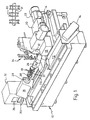
- Figure 1 shows a grinding machine 10 having a grinding wheel 12 driven by a motor 14 and mounted on a wheelhead 16 for movement towards and away from a workpiece 18 along a linear track 20 under the control of the wheelfeed drive motor 22.
- the workpiece 18 is mounted no a carriage 70 itself slidable on a slideway 72 and driven therealong to position the workpiece relative to the wheel, via a drive 74.
- the workpiece is mounted between centres in a tailstock 24 and a headstock 26 (themselves mounted on the carriage 70).
- the headstock houses a motor (not shown) for rotating the workpiece 18 via a chuck 28.
- the workpiece shown is a crankshaft of an internal combustion engine and includes offset crankpins 30 (which are eccentric to the main workshaft axis), and cylindrical bearing regions 31, which are to be ground to size, each bearing region constituting a cylindrical workpiece region for grinding which should be concentric with the workpiece axis.
- a computer 32 loaded with workpiece data and oeprating programmes controls the operation of the machine and inter alia moves the wheelhead 16 towards and away from the workpiece 18 as the workpiece rotates, so as to maintain contact between the wheel and the journal bearing region being ground.
- Some data can be entered via the keyboard 33.
- Data/results/process steps can be displayed on the screen 35.
- a gauge, generally designated 34, is carried by the wheel head assembly for gauging the diameter of the regions being ground. This can be done while the workpiece is rotated slowly, and preferably without the grinding wheel in contact, after grinding.
- the gauge is shown in its parked, non-operating position in Figure 1. During gauging it is advanced so that the fingers of the gauge (described in more detail with reference to Figure 2) are first located on the opposite side of the workpiece from the wheel 12, so that they can be lowered and moved back towards the wheel so as to be located above and below the workpiece, and then moved towards the latter until they touch it at diametrically opposite regions for gauging.
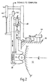
- the gauge will allow the gauging of crankpins such as 30 as they are ground, but Figure 2 shows how the fingers 36 and 38 can also engage a cylindrical bearing region 31.
- Pneumatic drives 44, 46 and 48 produce relative movement between the gauge assembly and the wheelhead 16, between the gauge assembly and the workpiece, and between the two fingers 36 and 38.
- a sensor 50 determines the spacing between the fingers 36, 38 and provides a size signal for the computer 32, from which the diameter of the workpiece region between the fingers can be computed.
- the sensor can also provide a signal indicative of the linear oscillatory movement of the gauge fingers caused by any eccentricity in the ground region, by locking the two fingers 36, 38 together but spaced so as to just lightly clamp the workplace therebetween, and rotating the latter slowly and observing any movement of 38 relative to sensor 50.
- Figure 3 shows diagrammatically the grinding wheel 12, the wheelhead 16, the slide 20, and a different type of gauge from that shown in Figures 1 and 2.
- This engages a cylindrical workpiece region 31 by means of two fixed converging fingers 52, 54, with a sensor 55 producing a signal from which the distance between the converging fingers at which the fingers make contact with the workpiece can be determined.
- the computer 32 receives the signal along line 56 and can compute therefrom the diameter of the workpiece region.
- Position and wheelhead drive signals from the computer 32 pass via line 59. Not shown are the signal paths from the computer 32 to the other drives for moving the gauge into and out of engagement and controlling the speed of rotation of the wheel and the crankshaft.
- this type of gauge can also be used to determine any eccentricity in the rotating workpiece region, by urging the gauge fingers 52, 54 into contact as shown and converting any in line movement of the gauge assembly 60, due to eccentricity, as the workpiece rotates into an appropriate electrical signal using a transducer such as 57.
- Wheel position signals from a transducer/encoder 41 are passed to the computer 32 via line 43.
- An encoder 37 or other transducer converts rotation of the workpiece 31 into angular informature. Signals along line 39 enable the phase of any eccentricity of 31 to be determined by the computer 32.
- the feed will be stopped in response to signals derived from the wheel position and/or the in-process gauge 34 in a diameter measuring mode, and sampled by the machine control computer 32.
- the instantaneous size of the region 31 being ground can be continuously sampled by the machine control computer.
- the controlling computer If one or two or more consecutive samples of region 31 size, are found to be at or below the target size, the controlling computer immediately stops the grinding feed and initiates a feed dwell.
- This dwell measured as N workpiece turns, permits the region being ground to achieve good geometric roundness and a stable size. This procedure gives an optimum response to fast grinding feeds commensurate with fast manufacturing times.
- the controlling computer stores a number of consecutive samples of size measured at different angular positions relative to the gauge fingers so that it can calculate an average value of the workpiece region diameter.
- the average diameter value may be calculated, and this value used to calculate the feed distance to achieve the desired final size of the region.
- the controlling computer then initiates an incremental feed to final size.
- the gauge having completed its work, can be retracted, with the object of minimising manufacturing time. Because the feed to final size is not being controlled by gauge, it does not have to be slow but can be optimised to eliminate the build-up of machining vibrations and/or minimise machining time.
- the grinding wheel can be retracted, initially at a slow rate so as not to leave any grinding wheel breakaway mark, and then at a faster rate to minimise manufacturing time.
- machining may be achieved without such in process gauging, simply by controlling the wheel feed and gauging components off-line, and correcting for process induced eccentricity in accordance with the present invention and for wheel wear by appropriate adjustment as the grinding of a batch of workpieces progresses.
- Figure 4 illustrates the steps of a method of grinding an elongate component having a number of different regions therealong which are to be cylindrically ground either concentrically or eccentrically to the primary axis of the component, and in which process induced eccentricity is corrected for all such regions whether ground to be concentric or eccentric to the primary axis.
Description
- This invention concerns a method of grinding workpieces to form components which include both concentric and eccentric cylindrical regions. Such a component may be an internal combustion engine crankshaft, which includes both concentric journal bearing regions and eccentric crankpins. The invention is applicable to any such workpiece which is to be ground to size and finish, and such workpieces will be referred to herein as composite workpieces.
- Historically, workpieces of this nature have been ground on two grinding machines. A first grinding machine has been used to grind the concentric cylindrical sections and a second grinding machine has been used to grind the eccentric cylindrical sections.
- In the first grinding machine the workpiece is rotated about its primary axis and each of the concentric sections are ground by moving a grinding wheel into a grinding position and removing material from the workpiece to produce a concentric cylindrical region thereon, in a conventional manner.
- In the second grinding machine, two approaches have been adopted. In one approach the workpiece has been rotated about the axis of each eccentric region in turn, and conventional cylindrical grinding is employed to remove material so as to produce a cylindrical bearing surface at each eccentric region, just as if the element were a concentric cylindrical region of an overall workpiece. In the second approach, the workpiece has been rotated about its primary axis so that the eccentric regions precess eccentrically around the primary axis of rotation, as for example do the crankpins of a crankshaft when the latter is mounted in and is rotated in an engine. In this second approach the grinding wheel has been aligned with an eccentric region and then been advanced and retracted under computer control in synchronism with the precession of the eccentric region so that the grinding wheel remains in contact therewith at all times. The region is thereby ground at all positions of its precession. As each eccentric region is ground to size, the grinding wheel is withdrawn and the workpiece or grinding wheel is repositioned axially so that another eccentric region is aligned with the grinding wheel, ready for a similar grinding operation at the new location.
- A process requiring two grinding machines involves considerable down-time as components are moved from one machine to another.
- During any grinding operation, but particularly noticeable when grinding regions of an elongate workpiece (such as a crankshaft) which is supported for grinding at its ends, unwanted eccentricity may be introduced into the workpiece due to forces acting on the workpiece during the grinding process. This eccentricity which is termed runout tends to be more noticeable in concentrically ground cylindrical regions of the workpiece. It often appears as a consequence of stress relieving the workpiece, after grinding, and any eccentricity introduced into concentrically ground journal bearing regions a crankshaft will introduce undesirable wear in the component when mounted and rotated in use.
- In FR-A-2426534 there is disclosed a computer control unit for a crankshaft milling/grinding machine, in which a digital transducer coupled to the work spindle continuously transmits positional data of the crankshaft to the computer, to enable it to control the machining of the crankpins and cheeks of the crankshaft.
- EP-A-0576043 discloses an NC machine tool for grinding a non-circular workpiece. A work spindle and tool slide are moved in accordance with a compensated profile data stored in a computer memory, and positional data of the spindle and slide are measured at low machining load and compared with the profile data to ascertain whether the compensation is within a predetermined tolerance.
- However, neither of the foregoing pieces of prior art is directed at the problems of grinding composite workpieces having cylindrical regions and reducing unwanted process-induced eccentricity in such regions.
- It is one object of the invention to reduce the machining time required to machine composite workpieces containing both concentric and eccentric regions, such as crankshafts which contain concentric journal bearing regions.
- It is a subsidiary object of the invention to reduce unwanted eccentricity of concentrically ground cylindrical regions of a composite workpiece such as concentric cylindrical bearing regions.
- It is a further object to provide a method of setting up a grinding machine which will not only reduce machining time of composite workpieces, but also allows ecxentricity correction to be applied to both concentrically and eccentrically ground cylindrical workpiece regions such as the journal bearing regions of an engine crankshaft.
- According to the present invention there is provided a method of setting up a computer controlled grinding machine for grinding an elongate composite workpiece having concentric cylindrical regions, with compensation for process-induced eccentricity in at lesst one of said concentric regions, in which said concentric region is cylindrically ground to final form, characterised by the steps of measuring any unwanted eccentricity introduced by the grinding process together with the angular position (s) thereof in said concentric region, and adjusting the wheelfeed programme instructions or control signals stored in the computer controlling the grinding machine, so that during subsequent workpiece grinding, the wheel feed is controlled in order to grind an equal and opposite eccentric form to that measured, thereby to cancel out process-induced eccentricity.
- The invention thus allows a workpiece having both concentric and eccentric cylindrical regions thereon to be ground on a single grinding machine without demounting the workpiece from the machine. This enables a workpiece to be left in place between centres whilst different regions therealong are ground to form cylindrical surfaces some of which are concentric with the primary axis of rotation of the workpiece, and others of which are eccentric relative thereto.
- The invention is of particular application to the grinding of crankshafts which have both eccentric regions and journal bearing regions which have to be ground as cylindrical surfaces concentric with the primary axis of rotation of the crankshaft.
- During the grinding of any workpiece, stresses and strains introduced by the grinding process particularly in unsupported regions of the workpiece, can cause a cylindrical region which is being ground to become eccentric relative to the primary workpiece axis. Whilst these eccentricities may be of minor consequence in the case of a significantly eccentric region such as a crankpin of a crankshaft, minor eccentricities in what should be concentric cylindrical surface, such as a journal bearing surface of a crankshaft, will result in friction and wear in an internal combustion engine in which such a crankshaft is mounted. The present invention enables this problem to be overcome
- Preferably the measuring of the workpiece region occurs after it has been stress relieved, which may be achieved merely by disengaging the grinding wheel, but may involve removing the workpiece from the grinding machine for gauging, then the careful replacement of the workpiece back in position.
- Any unwanted eccentricity introduced into a workpiece by a grinding process will tend to vary from one position to another along the length of the workpiece, and will tend to increase with distance from a supported workpiece end. In consequence for example cylindrical journal bearing regions and crankpins near the centre of a crankshaft which is supported at opposite ends may require a greater degree of eccentricity compensation than is the case for those near to the two supported ends.
- Thus where a plurality of such concentric regions are to be ground at spaced apart positions axially along the workpiece which is supported at opposite ends, the setting up process may be performed for a concentric cylindrical region approximately midway along the said axial length of the workpiece, and proportionately reduced corrections are applied to the wheelfeed programme instructions or control signals for similar cylindrical regions which are to be ground and which are displaced from the mid position towards the supported ends of the workpiece.
- In an alternative method, it is possible to more fully take into account the variation in unwanted eccentricity introduced by grinding process forces along the axial length an elongate wrkpiece supported at opposite ends, such that regions towards the centre of the workpiece, tend to require a greater degree of eccentricity compensation during grinding than do those adjacent the supported ends thereof. This alternative method involves the steps of concentrically grinding all of the concentric surfaces of a workpiece without introducing any compensation for unwanted process induced eccentricity thereafter making measurements on the workpiece to determine the extent and angular position of any unwanted eccentricity for each of the ground regions, and separately adjusting the wheelfeed programme instructions or control signals used to control the wheel feed during subsequent grinding of each said region of the same of a similar workpiece, so as to compensate individually for each said region for any process-induced eccentricity.
- After such a setting up process has been performed and the original workpiece has been reground using the corrected wheelfeed programme instructions or control signals a further check on the reground workpiece may be made and second order corrections may be made to the instructions or control signals, before regrinding the original workpiece or grinding further similar workpieces.
- Instead of producing only one workpiece on which measurements are made during setting up, it may be preferable at each stage to grind a number of workpieces which together form a sample, and to perform eccentricity measurements on the workpieces in each sample, and thereby determine the extent of any unwanted eccentricity both in terms of angular position and radial extent for each region of each workpiece in each sample, and to determine the mean unwanted eccentricity and mean angular position of such eccentricity for each sample, for use as the basis for the correction to the wheel feed control signals for subsequent grinding.
- Where plural samples of workpieces are used to determine the corrections to be made, the process for determining what is to be the final set of control signals for the wheelfeel, can be terminated either if all of the measurements of unwanted eccentricity in all of the workpieces in a sample fall within desired limits, or if the mean of all the measurements of unwanted eccentricity fall within desired limits. The particular criterion used may depend upon the specification for the component concerned.
- The invention may be applied to the above method in which the workpiece is a crankshaft having concentric regions and eccentric cylindrical crankpin regions, and in which a software controlled crankpin following facility is used to permit the grinding wheel to follow the relatively excessive eccentric movement of the crankpins as the crankshaft rotates during grinding comprising the steps of adapting the software to provide at a smaller scale a complementary eccentricity to the unwanted eccentricity which is introduced into the concentric cylindrical surfaces of the workpiece as a consequence of grinding process forces exerted as such surfaces are ground, and which tends to appear after the workpiece is stress relieved, so as to cancel out the process-induced eccentricity.
- Whilst the invention is of particular application to the grinding of crankpins and journal bearing regions on elongate crankshafts, it is to be understood that it is equally applicable to the grinding of any composite workpiece so as to remove eccentricity which the grinding process can introduce into the workpiece, and which becomes evident as the latter becomes unstressed.
- Other features of the invention are defined in the appended claims.
- The invention will now be described by way of example with reference to the accompanying drawings, in which:
- Figure 1 illustrates a computer controlled grinding machine, fitted with an in process gauge;
- Figure 2 is a side view of the gauge to an enlarged scale;
- Figure 3 is a diagrammatic illustration of how a gauge is controlled and in turn controls the grinding cycle, via the machine controlling computer; and
- Figures 4 is an example of the grinding process steps of the method according to the invention.
-
- Figure 1 shows a
grinding machine 10 having a grindingwheel 12 driven by amotor 14 and mounted on awheelhead 16 for movement towards and away from aworkpiece 18 along alinear track 20 under the control of thewheelfeed drive motor 22. Theworkpiece 18 is mounted no acarriage 70 itself slidable on aslideway 72 and driven therealong to position the workpiece relative to the wheel, via adrive 74. The workpiece is mounted between centres in atailstock 24 and a headstock 26 (themselves mounted on the carriage 70). The headstock houses a motor (not shown) for rotating theworkpiece 18 via achuck 28. The workpiece shown is a crankshaft of an internal combustion engine and includes offset crankpins 30 (which are eccentric to the main workshaft axis), andcylindrical bearing regions 31, which are to be ground to size, each bearing region constituting a cylindrical workpiece region for grinding which should be concentric with the workpiece axis. - A
computer 32 loaded with workpiece data and oeprating programmes (such as are to be described) controls the operation of the machine and inter alia moves thewheelhead 16 towards and away from theworkpiece 18 as the workpiece rotates, so as to maintain contact between the wheel and the journal bearing region being ground. Some data can be entered via thekeyboard 33. Data/results/process steps can be displayed on thescreen 35. - A gauge, generally designated 34, is carried by the wheel head assembly for gauging the diameter of the regions being ground. This can be done while the workpiece is rotated slowly, and preferably without the grinding wheel in contact, after grinding. The gauge is shown in its parked, non-operating position in Figure 1. During gauging it is advanced so that the fingers of the gauge (described in more detail with reference to Figure 2) are first located on the opposite side of the workpiece from the
wheel 12, so that they can be lowered and moved back towards the wheel so as to be located above and below the workpiece, and then moved towards the latter until they touch it at diametrically opposite regions for gauging. - The gauge will allow the gauging of crankpins such as 30 as they are ground, but Figure 2 shows how the
fingers 36 and 38 can also engage acylindrical bearing region 31. Pneumatic drives 44, 46 and 48 produce relative movement between the gauge assembly and thewheelhead 16, between the gauge assembly and the workpiece, and between the twofingers 36 and 38. - A
sensor 50 determines the spacing between thefingers 36, 38 and provides a size signal for thecomputer 32, from which the diameter of the workpiece region between the fingers can be computed. The sensor can also provide a signal indicative of the linear oscillatory movement of the gauge fingers caused by any eccentricity in the ground region, by locking the twofingers 36, 38 together but spaced so as to just lightly clamp the workplace therebetween, and rotating the latter slowly and observing any movement of 38 relative tosensor 50. - Figure 3 shows diagrammatically the grinding
wheel 12, thewheelhead 16, theslide 20, and a different type of gauge from that shown in Figures 1 and 2. This engages acylindrical workpiece region 31 by means of two fixed convergingfingers sensor 55 producing a signal from which the distance between the converging fingers at which the fingers make contact with the workpiece can be determined. Thecomputer 32 receives the signal alongline 56 and can compute therefrom the diameter of the workpiece region. Position and wheelhead drive signals from thecomputer 32 pass vialine 59. Not shown are the signal paths from thecomputer 32 to the other drives for moving the gauge into and out of engagement and controlling the speed of rotation of the wheel and the crankshaft. Although developed to measure crankpin during grinding, this type of gauge can also be used to determine any eccentricity in the rotating workpiece region, by urging thegauge fingers gauge assembly 60, due to eccentricity, as the workpiece rotates into an appropriate electrical signal using a transducer such as 57. - Wheel position signals from a transducer/
encoder 41 are passed to thecomputer 32 vialine 43. - An encoder 37 or other transducer converts rotation of the
workpiece 31 into angular informature. Signals alongline 39 enable the phase of any eccentricity of 31 to be determined by thecomputer 32. - As described in our copending UK Application 9702550.6 which describes a method of guiding crankpins to size using in process gauging, a technique is also described to obtain a high quality surface finish and highly accurate diameters of ground components. This technique may also be used when grinding journal bearing regions. Thus during grinding, an initial fast wheelfeed may be used to roundout
journal bearing region 31, and the fast grinding feed stopped after a fixed feed amount independent of the gauge. At the end of the fast feed thegauge 34 is used by the machine control computer to sample the size of theregion 31 and to check any eccentricity in magnitude and angular position as determined by the rotated position of the workpiece at which the eccentricity is noted. A prerequisite for the grinding cycle to proceed beyond this point is that this sample of size sensibly confirms that the gauge is on the region and functioning properly. - After computing the necessary control signal to compensate for any measured eccentricity the grinding feed restarts. A lower feed rate may be used.
- In normal operation the feed will be stopped in response to signals derived from the wheel position and/or the in-
process gauge 34 in a diameter measuring mode, and sampled by themachine control computer 32. - In a method, which involves in process gauging as the grinding feed proceeds towards a target size, near final size the instantaneous size of the
region 31 being ground can be continuously sampled by the machine control computer. - If one or two or more consecutive samples of
region 31 size, are found to be at or below the target size, the controlling computer immediately stops the grinding feed and initiates a feed dwell. This dwell, measured as N workpiece turns, permits the region being ground to achieve good geometric roundness and a stable size. This procedure gives an optimum response to fast grinding feeds commensurate with fast manufacturing times. During this feed dwell, typically two work revolutions, the controlling computer stores a number of consecutive samples of size measured at different angular positions relative to the gauge fingers so that it can calculate an average value of the workpiece region diameter. - At the completion of this dwell, the average diameter value may be calculated, and this value used to calculate the feed distance to achieve the desired final size of the region. The controlling computer then initiates an incremental feed to final size. At the start of this incremental feed, the gauge, having completed its work, can be retracted, with the object of minimising manufacturing time. Because the feed to final size is not being controlled by gauge, it does not have to be slow but can be optimised to eliminate the build-up of machining vibrations and/or minimise machining time.
- After a final "sparkout feed dwell", measured as n workpiece turns, the grinding wheel can be retracted, initially at a slow rate so as not to leave any grinding wheel breakaway mark, and then at a faster rate to minimise manufacturing time.
- Alternatively, machining may be achieved without such in process gauging, simply by controlling the wheel feed and gauging components off-line, and correcting for process induced eccentricity in accordance with the present invention and for wheel wear by appropriate adjustment as the grinding of a batch of workpieces progresses.
- Figure 4 illustrates the steps of a method of grinding an elongate component having a number of different regions therealong which are to be cylindrically ground either concentrically or eccentrically to the primary axis of the component, and in which process induced eccentricity is corrected for all such regions whether ground to be concentric or eccentric to the primary axis.
- Detailed programme steps required to set up and operate a grinding machine in different ways in accordance with different aspects of the invention, so as to allow so-called composite workpieces to be ground on the same computer controlled grinding machine, with or without correction for process induced eccentricity, are now listed, on the following pages.
- The lists of controlled operations which follow illustrate the steps which the machine controlling computer must initiate the inputs it must respond to, and the decisions it must make, under the control of programmes loaded into its memory, so as to adjust the wheelfeed programme instructions or control signals and other machine parameters, and parts, so as to set up the machine to therafter grind a composite workpiece such as a crankshaft in accordance with different methods embodying the invention, as detailed.
- A brief explanation of the process to which the steps relate is provided at the head of each listing.
- I. Instructions for setting up and running a computer_controlled grinding machine to grind
similar composite workpieces without eccentricity correction of cylindrically_ground regions
of the workpiece
- 1. Load composite workpiece data into machine computer
- 2. Load wheelfeed routines into machine computer
- 3. Identify axial positions of workpiece regions to be ground
- 4. Mount workpiece
- 5. Rotate workpiece for grinding
- 6. Align grinding wheel with region to be ground
- 7. Determine from workpiece data how region is to be ground
- 8. If concentric grinding, go to 9; if eccentric go to 28
- 9. Select concentric wheelfeed grinding routine
- 10. Advance wheel to engage workpiece region
- 11. Compute wheel positon to achieve a target diameter
- 12. Grind and measure wheel advance from engagement
- 13. Stop wheelfeed at target diameter position
- 14. Disengage wheel
- 15. Apply gauge and measure ground diameter
- 16. Adjust wheelfeed instructions to achieve final diameter
- 17. Compute wheel position to achieve final diameter
- 18. Advance wheel to engage workpiece
- 19. Grind and measure wheel advance from engagement
- 20. Stop wheelfeed when computed position is achieved
- 21. Retract wheel
- 22. More regions to grind? Yes or No
- 23. If Yes, go to 6; if No go to 24
- 24. Demount workpiece
- 25. More workpieces? Yes or No
- 26. If Yes, go to 4; if No, go to 27
- 27. Enter standby mode
- 28. Select eccentric wheelfeed grinding routine
- 29. Go to 10
- II. Instructions for setting up and grinding a computer_controlled grinding machine to grind
similar composite_workpieces with eccentricity correction of cylindrically_ground
concentric regions thereof
- 1. Load composite workpiece data into machine computer
- 2. Load wheelfeed routines into machine computer
- 3. Identify axial positions of workpiece regions to be ground
- 4. Mount workpiece
- 5. Rotate workpiece for grinding
- 6. Align grinding wheel with region to be ground
- 7. Determine from workpiece data how region is to be ground
- 8. If concentric grinding, go to 9; if eccentric go to 28
- 9. Select concentric grinding wheelfeed routine
- 10. Advance wheel to engage workpiece region
- 11. Compute wheel positon to achieve a target diameter
- 12. Grind and measure wheel advance from engagement
- 13. Stop wheelfeed at target diameter position
- 14. Disengage wheel
- 15. Rotate workpiece slowly
- 16. Gauge ground region and store diameter
- 17. Identify any eccentricity and its rotational positin
- 18. Adjust selected wheelfeed routine for eccentricity
- 19. Compute wheel position to achieve final diameter
- 20. Rotate workpiece for grinding
- 21. Advance wheel and engage workpiece region
- 22. Regrind using adjusted routine and measure wheel advance
- 23. Stop wheelfeed when computed position is achieved
- 24. Retract wheel
- 25. More regions to grind? Yes or No
- 26. If Yes, go to 6; if No, go to 27
- 27. Demount workpiece
- 28. More workpieces? Yes or No
- 29. If Yes go to 4; if No go to 30
- 30. Enter standby mode
- 31. Select eccentric grinding wheelfeed routine
- 32. Advance wheel to enage workpiece region
- 33. Compute wheel position to achieve target diameter
- 34. Grind and measure wheel advance and engagement
- 35. Stop wheelfeed at computed position
- 36. Disengage wheel from eccentric workpiece region
- 37. Apply gauge and measure diameter of eccentric region
- 38. Adjust wheelfeed to achieve final diameter
- 39. Compute wheel position to achieve final diameter
- 40. Advance wheel to engage eccentric workpiece region
- 41. Grind and measure wheel advance from engagement
- 42. Stop wheelfeed when computed position is achieved
- 43. Retract wheel and go to 25
- 44. More workpieces to grind? Yes or No
- 45. If Yes, go to 6; if No, go to 30
-
Claims (9)
- A method of setting up a computer controlled grinding machine (10) for grinding an elongate composite workpiece (18) having concentric cylindrical regions (31), with compensation for process-induced eccentricity in at least one of said concentric regions, in which said concentric region is cylindrically ground to final form, characterised by the steps of measuring (50) any unwanted eccentricity introduced by the grinding process together with the angular position(s) thereof in said concentric region, and adjusting the wheelfeed programme instructions or control signals stored in the computer (32) controlling the grinding machine, so that during subsequent workpiece grinding, the wheel feed is controlled in order to grind an equal and opposite eccentric form to that measured, thereby to cancel out process-induced eccentricity.
- A method as claimed in claim 1, in which the step of measuring any unwanted eccentricity is performed after said concentric region has been stress relieved.
- A method as claimed in claim 1 or claim 2, in which a plurality of concentric regions are to be ground at spaced apart positions axially along the composite workpiece which is supported at opposite ends for grinding, the setting up process being performed for said one concentric cylindrical region approximately midway along the axial length of the workpiece, and in which proportionately reduced corrections are applied to the wheelfeed programme instructions or control signals for similar cyindrical regions which are to be ground and which are displaced from the midway position towards the supported ends of the workpiece.
- A method as claimed in claim 1 or claim 2, in which the regions towards the centre of the workpiece tend to require a greater degree of ecentricity compensation than do those adjacent the supported ends thereof, which method involves the steps of cylindrically grinding all of the concentric cylindrical surfaces of the workpiece without introducing any compensation for unwanted process-induced eccentricity, thereafter making measurements on the workpiece to determine the extent and angular position of any unwanted eccentricity for each of the ground regions, and separately adjusting the wheelfeed programme instructions or control signals to be used to control the wheel feed during subsequent grinding of each said region of the same or similar workpieces, so as to compensate individually for each said region for any process-induced eccentricity.
- A method as claimed in claim 4, wherein after the setting up process has been performed the original workpiece is reground using the corrected wheelfeed programme instructions or control signals, and a further measuring step is performed on the reground workpiece and second order corrections are made to the programme instructions or control signals, before regrinding the original workpiece or grinding further similar workpieces.
- A method as claimed in any one of claims 1 to 5, wherein instead of producing only one workpiece on which measurements are made during setting up, at each stage a number of workpieces are ground which together form a sample, and eccentricity measurements are performed on the workpieces in each sample, thereby to determine the extent of any unwanted eccentricity both in terms of angular position and radial extent for each region of each workpiece in each sample, and the mean unwanted eccentricity and mean angular position of such eccentricity are determined for each sample, for use each as the basis for the correction to the wheelfeed programme instructions or control signals for subsequent grinding.
- A method as claimed in any one of claims 1 to 5, in which modified wheel feed programme instructions or control signals, derived from the setting up procedure, are used to control the wheelfeed drive when grinding cylindrical surfaces of composite workpieces similar to that used in the setting up process.
- A method as claimed in any one of claims 1 to 7, in which the workpiece is a crankshaft having concentric regions and eccentric cylindrical crankpin regions, and in which a software controlled crankpin following facility is used to permit the grinding wheel to follow the relatively excessive eccentric movement of the crankpins as the crankshaft rotates during grinding comprising the steps of adapting the software to provide at a smaller scale a complementary eccentricity to the unwanted eccentricity which is introduced into the concentric cylindrical surfaces of the workpiece as a consequence of grinding process forces exerted as such surfaces are ground, and which tends to appear after the workpiece is stress relieved, so as to cancel out the process-induced eccentricity.
- A method as claimed in claim 8, in which the degree of said complementary eccentricity provided is such that when the ground workpiece is stress relieved after grinding the region will be concentric relative to the primary axis of the workpiece, and in which the same computer control of the wheelfeed albeit at a larger scale is employed to grind the crankpin using the same wheel on the same machine.
Applications Claiming Priority (3)
| Application Number | Priority Date | Filing Date | Title |
|---|---|---|---|
| GBGB9608351.4A GB9608351D0 (en) | 1996-04-23 | 1996-04-23 | Composite component grinding method and apparatus |
| GB9608351 | 1996-04-23 | ||
| EP97919518A EP0895614B1 (en) | 1996-04-23 | 1997-04-22 | Method and apparatus for grinding composite workpieces |
Related Parent Applications (1)
| Application Number | Title | Priority Date | Filing Date |
|---|---|---|---|
| EP97919518A Division EP0895614B1 (en) | 1996-04-23 | 1997-04-22 | Method and apparatus for grinding composite workpieces |
Publications (3)
| Publication Number | Publication Date |
|---|---|
| EP0984343A2 EP0984343A2 (en) | 2000-03-08 |
| EP0984343A3 EP0984343A3 (en) | 2000-03-15 |
| EP0984343B1 true EP0984343B1 (en) | 2003-01-15 |
Family
ID=10792483
Family Applications (2)
| Application Number | Title | Priority Date | Filing Date |
|---|---|---|---|
| EP99123806A Expired - Lifetime EP0984343B1 (en) | 1996-04-23 | 1997-04-22 | Method of grinding composite workpieces |
| EP97919518A Expired - Lifetime EP0895614B1 (en) | 1996-04-23 | 1997-04-22 | Method and apparatus for grinding composite workpieces |
Family Applications After (1)
| Application Number | Title | Priority Date | Filing Date |
|---|---|---|---|
| EP97919518A Expired - Lifetime EP0895614B1 (en) | 1996-04-23 | 1997-04-22 | Method and apparatus for grinding composite workpieces |
Country Status (10)
| Country | Link |
|---|---|
| US (1) | US6411861B1 (en) |
| EP (2) | EP0984343B1 (en) |
| AU (1) | AU2395897A (en) |
| BR (1) | BR9706668A (en) |
| CA (1) | CA2225962C (en) |
| DE (2) | DE69718520T2 (en) |
| ES (2) | ES2190171T3 (en) |
| GB (2) | GB9608351D0 (en) |
| MX (1) | MX9804292A (en) |
| WO (1) | WO1997040432A1 (en) |
Cited By (1)
| Publication number | Priority date | Publication date | Assignee | Title |
|---|---|---|---|---|
| CN101154098B (en) * | 2006-09-28 | 2011-01-19 | 株式会社捷太格特 | numerical controller and program writing method thereof, and cutting machine controlled thereby |
Families Citing this family (23)
| Publication number | Priority date | Publication date | Assignee | Title |
|---|---|---|---|---|
| AU2480300A (en) * | 1998-12-16 | 2000-07-03 | University Of Massachusetts | Grinding wheel system |
| GB9928825D0 (en) * | 1999-12-06 | 2000-02-02 | Unova Uk Ltd | Improvements in and relating to grinding |
| JP4051872B2 (en) * | 2000-09-29 | 2008-02-27 | 株式会社ジェイテクト | Measuring method of processing part and processing method |
| KR100782393B1 (en) * | 2000-10-26 | 2007-12-07 | 신에쓰 가가꾸 고교 가부시끼가이샤 | A method of manufacturing a preform ingot for optical fiber |
| DE10104287B4 (en) * | 2001-01-30 | 2006-08-24 | Sirona Dental Systems Gmbh | Method for determining current position data of a machining tool and device for this purpose |
| US7657757B2 (en) | 2003-04-30 | 2010-02-02 | Freescale Semiconductor, Inc. | Semiconductor device and method utilizing variable mode control with block ciphers |
| DE10344293A1 (en) * | 2003-09-23 | 2005-04-21 | Walter Ag | Grinding machine with concentricity correction |
| TWI388397B (en) * | 2004-02-25 | 2013-03-11 | Studer Ag Fritz | Machine for machining workpieces |
| US7226340B2 (en) * | 2004-03-05 | 2007-06-05 | Alfred H. Schutte Gmbh & Co. Kg | Grinding machine |
| JP5401757B2 (en) * | 2006-11-30 | 2014-01-29 | 株式会社ジェイテクト | Processing equipment |
| DE102008007175B4 (en) * | 2008-02-01 | 2010-06-02 | Erwin Junker Maschinenfabrik Gmbh | Method for grinding the main and stroke bearings of a crankshaft by external cylindrical grinding and apparatus for carrying out the method |
| JP5228554B2 (en) * | 2008-03-19 | 2013-07-03 | 株式会社ジェイテクト | Workpiece abnormal rotation detection device for non-round grinding machine |
| GB2475391B (en) * | 2009-07-28 | 2013-02-27 | Komatsu Ntc Ltd | Grinding machine and measurement device |
| JP5064571B2 (en) * | 2009-07-28 | 2012-10-31 | コマツNtc株式会社 | Grinding machine and measuring device |
| JP5708324B2 (en) * | 2011-07-11 | 2015-04-30 | 日本精工株式会社 | Grinding machine and grinding method |
| EP2650081B1 (en) * | 2012-04-13 | 2013-11-27 | Supfina Grieshaber GmbH & Co. KG | Method and device for finishing a workpiece surface |
| JP6186739B2 (en) * | 2013-02-15 | 2017-08-30 | 株式会社ジェイテクト | Grinding machine and grinding method |
| DE102013222359B4 (en) * | 2013-11-04 | 2018-05-09 | Gebr. Heller Maschinenfabrik Gmbh | Process for fine machining of shafts, in particular crankshafts, and fine machining plant therefor |
| DE102013226733B4 (en) * | 2013-12-19 | 2021-12-23 | Erwin Junker Grinding Technology A.S. | PROCESS AND GRINDING MACHINE FOR MEASURING AND GENERATING AN OUTER TARGET CONTOUR OF A WORKPIECE BY GRINDING |
| CN103802023B (en) * | 2014-03-06 | 2016-04-27 | 吉林大学 | The speed-optimization control method of numerically control grinder cam ground |
| US10132167B2 (en) * | 2014-06-16 | 2018-11-20 | United Technologies Corporation | Methods for creating a film cooled article for a gas turbine engine |
| CN104325405B (en) * | 2014-11-19 | 2017-02-08 | 武汉大学 | Ultra-fine filament grinding tool positioning system and method |
| JP2022553403A (en) * | 2019-10-24 | 2022-12-22 | ファイブズ・ランディス・コーポレーション | Methods of grinding and turning workpieces |
Family Cites Families (26)
| Publication number | Priority date | Publication date | Assignee | Title |
|---|---|---|---|---|
| GB674065A (en) * | 1948-06-10 | 1952-06-18 | Robert Musyl | Improvements in or relating to machines for grinding the main bearing pins and crank pins of crankshafts |
| JPS5457285A (en) | 1977-10-14 | 1979-05-08 | Komatsu Ltd | Crankshaft mirror control device |
| DE2822346C2 (en) | 1978-05-22 | 1985-09-05 | GFM Gesellschaft für Fertigungstechnik und Maschinenbau GmbH, Steyr | Electric numerical program control for crankshaft milling machines and crankshaft grinding machines |
| AT373405B (en) | 1978-10-04 | 1984-01-25 | Gfm Fertigungstechnik | ELECTRICAL CONTROL DEVICE FOR A CUTTING MACHINE TOOL FOR MACHINING CRANKSHAFT |
| DE2918249A1 (en) * | 1979-05-05 | 1980-11-06 | Goetze Ag | MACHINE FOR PREFERABLY CHANGING CIRCULAR MACHINING OF UNCIRCULAR WORKPIECES, IN PARTICULAR PISTON RINGS |
| JPS58192750A (en) * | 1982-05-03 | 1983-11-10 | Toyoda Mach Works Ltd | Grinding machine |
| US4580224A (en) | 1983-08-10 | 1986-04-01 | E. W. Bliss Company, Inc. | Method and system for generating an eccentricity compensation signal for gauge control of position control of a rolling mill |
| JPH0698554B2 (en) | 1986-09-22 | 1994-12-07 | 豊田工機株式会社 | Numerical control processing equipment |
| DE3702594C3 (en) * | 1987-01-29 | 1995-04-06 | Fortuna Werke Maschf Ag | Method and device for grinding cams on camshafts |
| GB2206067B (en) | 1987-06-25 | 1991-05-15 | Litton Uk Ltd | Crankpin grinders |
| DE3828594C2 (en) * | 1987-08-24 | 2002-04-25 | Toshiba Machine Co Ltd | Numerically controlled machine tool and method for controlling the grinding process carried out with it |
| FR2623741B1 (en) | 1987-11-26 | 1990-04-27 | Peugeot | CRANKSHAFT CROSSBAR RECTIFICATION ASSEMBLY |
| GB2219231A (en) | 1988-06-04 | 1989-12-06 | Ford Motor Co | Grinding workpieces |
| JP3030046B2 (en) * | 1990-03-22 | 2000-04-10 | 豊田工機株式会社 | Non-roundness generating device |
| FR2665526A1 (en) * | 1990-08-02 | 1992-02-07 | Meseltron Sa | DEVICE FOR MEASURING DIAMETERS OF CYLINDRICAL PARTS DURING PROCESSING. |
| US6205371B1 (en) * | 1990-08-11 | 2001-03-20 | Dieter Wolter-Doll | Method and apparatus for detecting machining flaws, especially caused by grinding machines |
| JP3021156B2 (en) * | 1991-12-25 | 2000-03-15 | オークマ株式会社 | Machining error correction method for non-circular processing machine |
| JP2811515B2 (en) * | 1992-04-25 | 1998-10-15 | オークマ株式会社 | Non-circular work grinding method and apparatus |
| JPH068105A (en) * | 1992-06-29 | 1994-01-18 | Komatsu Ltd | Cylindrically machining device |
| CA2081699C (en) * | 1992-08-14 | 1998-06-09 | James D. Phillips | Crankpin grinder |
| GB2283192B (en) * | 1993-10-20 | 1997-07-16 | Western Atlas Uk Ltd | Improvements in and relating to grinding machines |
| GB9509294D0 (en) * | 1995-05-06 | 1995-06-28 | Western Atlas Uk Ltd | Improvements relating to guaging the diameter of cylindrical workpiece sections |
| GB9514042D0 (en) | 1995-07-10 | 1995-09-06 | Western Atlas Uk Ltd | Improvements in and relating to machine tools |
| GB9603260D0 (en) * | 1996-02-16 | 1996-04-17 | Western Atlas Uk Ltd | Grinding method and apparatus for cylindrical workpieces |
| GB9608352D0 (en) * | 1996-04-23 | 1996-06-26 | Western Atlas Uk Ltd | Workpiece grinding method and apparatus |
| US6113461A (en) * | 1996-09-30 | 2000-09-05 | Ntn Corporation | Grinding method utilizing grinding sharpness of grinding element |
-
1996
- 1996-04-23 GB GBGB9608351.4A patent/GB9608351D0/en active Pending
-
1997
- 1997-04-22 DE DE69718520T patent/DE69718520T2/en not_active Expired - Fee Related
- 1997-04-22 DE DE69708858T patent/DE69708858T2/en not_active Expired - Fee Related
- 1997-04-22 EP EP99123806A patent/EP0984343B1/en not_active Expired - Lifetime
- 1997-04-22 CA CA002225962A patent/CA2225962C/en not_active Expired - Fee Related
- 1997-04-22 ES ES99123806T patent/ES2190171T3/en not_active Expired - Lifetime
- 1997-04-22 EP EP97919518A patent/EP0895614B1/en not_active Expired - Lifetime
- 1997-04-22 AU AU23958/97A patent/AU2395897A/en not_active Abandoned
- 1997-04-22 ES ES97919518T patent/ES2171258T3/en not_active Expired - Lifetime
- 1997-04-22 BR BR9706668A patent/BR9706668A/en not_active IP Right Cessation
- 1997-04-22 WO PCT/GB1997/001109 patent/WO1997040432A1/en active IP Right Grant
- 1997-04-22 US US09/011,081 patent/US6411861B1/en not_active Expired - Fee Related
- 1997-04-22 GB GB9708088A patent/GB2314285B/en not_active Expired - Fee Related
-
1998
- 1998-05-29 MX MX9804292A patent/MX9804292A/en not_active IP Right Cessation
Cited By (1)
| Publication number | Priority date | Publication date | Assignee | Title |
|---|---|---|---|---|
| CN101154098B (en) * | 2006-09-28 | 2011-01-19 | 株式会社捷太格特 | numerical controller and program writing method thereof, and cutting machine controlled thereby |
Also Published As
| Publication number | Publication date |
|---|---|
| EP0984343A3 (en) | 2000-03-15 |
| BR9706668A (en) | 1999-07-20 |
| CA2225962A1 (en) | 1997-10-30 |
| MX9804292A (en) | 1998-11-30 |
| DE69708858T2 (en) | 2002-04-11 |
| GB2314285B (en) | 2000-03-15 |
| DE69708858D1 (en) | 2002-01-17 |
| CA2225962C (en) | 2005-09-20 |
| US6411861B1 (en) | 2002-06-25 |
| DE69718520T2 (en) | 2003-09-25 |
| EP0984343A2 (en) | 2000-03-08 |
| GB2314285A (en) | 1997-12-24 |
| GB9608351D0 (en) | 1996-06-26 |
| ES2190171T3 (en) | 2003-07-16 |
| GB9708088D0 (en) | 1997-06-11 |
| AU2395897A (en) | 1997-11-12 |
| DE69718520D1 (en) | 2003-02-20 |
| EP0895614B1 (en) | 2001-12-05 |
| WO1997040432A1 (en) | 1997-10-30 |
| ES2171258T3 (en) | 2002-09-01 |
| EP0895614A1 (en) | 1999-02-10 |
Similar Documents
| Publication | Publication Date | Title |
|---|---|---|
| EP0984343B1 (en) | Method of grinding composite workpieces | |
| EP1193028B1 (en) | Method for measuring work portion and machining method | |
| US6767273B1 (en) | Crankpin grinding method | |
| US5251405A (en) | Method for circumferential grinding of radially non-circular workpieces | |
| EP1736278B1 (en) | Grinding method | |
| US6038489A (en) | Machine tools | |
| CA1109949A (en) | Grinding machine | |
| EP0895615B1 (en) | Methods and apparatus for grinding concentric cylindrical workpiece regions | |
| EP1380385B1 (en) | Method of simultaneously grinding a plurality of grinding portions on a workpiece | |
| JPH05277913A (en) | Process for grinding journal of crankshaft, and grinder therefor | |
| US4831787A (en) | Honing process | |
| GB2318074A (en) | Compensating for grinding inaccuracies | |
| US7818080B2 (en) | Program writing method of numerical controller, numerical controller and cutting machine controlled thereby | |
| EP0950214B1 (en) | Method of controlling a machine tool | |
| CN114364478B (en) | Gear cutting method and machine tool set using same | |
| JP2542084B2 (en) | Method for correcting the grinding surface of the grinding wheel | |
| US20220331893A1 (en) | Method for producing or machining, by cutting, an identical set of teeth on each of a plurality of workpieces, and machine group and control program therefor | |
| JP3104357B2 (en) | Adjustment method for the amount of retraction in internal grinding | |
| KR0171645B1 (en) | Workpiece inner cylindrical surface horning method and device thereof | |
| JP2001179587A (en) | Machining method of eccentric shaft part | |
| GB2351685A (en) | Workrest control in a multi-wheel grinding machine | |
| King et al. | Centerless Grinding | |
| JPH06304863A (en) | Grinding device |
Legal Events
| Date | Code | Title | Description |
|---|---|---|---|
| PUAI | Public reference made under article 153(3) epc to a published international application that has entered the european phase |
Free format text: ORIGINAL CODE: 0009012 |
|
| PUAL | Search report despatched |
Free format text: ORIGINAL CODE: 0009013 |
|
| 17P | Request for examination filed |
Effective date: 19991210 |
|
| AC | Divisional application: reference to earlier application |
Ref document number: 895614 Country of ref document: EP |
|
| AK | Designated contracting states |
Kind code of ref document: A2 Designated state(s): DE ES FR IT |
|
| AX | Request for extension of the european patent |
Free format text: AL;LT;LV;RO;SI |
|
| AK | Designated contracting states |
Kind code of ref document: A3 Designated state(s): AT BE CH DE DK ES FI FR GB GR IE IT LI LU MC NL PT SE |
|
| AX | Request for extension of the european patent |
Free format text: AL;LT;LV;RO;SI |
|
| AKX | Designation fees paid |
Free format text: DE ES FR IT |
|
| 17Q | First examination report despatched |
Effective date: 20010525 |
|
| GRAG | Despatch of communication of intention to grant |
Free format text: ORIGINAL CODE: EPIDOS AGRA |
|
| RTI1 | Title (correction) |
Free format text: METHOD OF GRINDING COMPOSITE WORKPIECES |
|
| GRAG | Despatch of communication of intention to grant |
Free format text: ORIGINAL CODE: EPIDOS AGRA |
|
| GRAH | Despatch of communication of intention to grant a patent |
Free format text: ORIGINAL CODE: EPIDOS IGRA |
|
| GRAH | Despatch of communication of intention to grant a patent |
Free format text: ORIGINAL CODE: EPIDOS IGRA |
|
| GRAA | (expected) grant |
Free format text: ORIGINAL CODE: 0009210 |
|
| AC | Divisional application: reference to earlier application |
Ref document number: 895614 Country of ref document: EP |
|
| AK | Designated contracting states |
Kind code of ref document: B1 Designated state(s): DE ES FR IT |
|
| REF | Corresponds to: |
Ref document number: 69718520 Country of ref document: DE Date of ref document: 20030220 Kind code of ref document: P |
|
| REG | Reference to a national code |
Ref country code: ES Ref legal event code: FG2A Ref document number: 2190171 Country of ref document: ES Kind code of ref document: T3 |
|
| ET | Fr: translation filed | ||
| PLBE | No opposition filed within time limit |
Free format text: ORIGINAL CODE: 0009261 |
|
| STAA | Information on the status of an ep patent application or granted ep patent |
Free format text: STATUS: NO OPPOSITION FILED WITHIN TIME LIMIT |
|
| 26N | No opposition filed |
Effective date: 20031016 |
|
| REG | Reference to a national code |
Ref country code: FR Ref legal event code: TP |
|
| PGFP | Annual fee paid to national office [announced via postgrant information from national office to epo] |
Ref country code: FR Payment date: 20080313 Year of fee payment: 12 Ref country code: ES Payment date: 20080418 Year of fee payment: 12 Ref country code: DE Payment date: 20080320 Year of fee payment: 12 |
|
| PGFP | Annual fee paid to national office [announced via postgrant information from national office to epo] |
Ref country code: IT Payment date: 20080331 Year of fee payment: 12 |
|
| REG | Reference to a national code |
Ref country code: FR Ref legal event code: CD |
|
| REG | Reference to a national code |
Ref country code: FR Ref legal event code: ST Effective date: 20091231 |
|
| PG25 | Lapsed in a contracting state [announced via postgrant information from national office to epo] |
Ref country code: DE Free format text: LAPSE BECAUSE OF NON-PAYMENT OF DUE FEES Effective date: 20091103 |
|
| PG25 | Lapsed in a contracting state [announced via postgrant information from national office to epo] |
Ref country code: FR Free format text: LAPSE BECAUSE OF NON-PAYMENT OF DUE FEES Effective date: 20091222 |
|
| REG | Reference to a national code |
Ref country code: ES Ref legal event code: FD2A Effective date: 20090423 |
|
| PG25 | Lapsed in a contracting state [announced via postgrant information from national office to epo] |
Ref country code: ES Free format text: LAPSE BECAUSE OF NON-PAYMENT OF DUE FEES Effective date: 20090423 |
|
| PG25 | Lapsed in a contracting state [announced via postgrant information from national office to epo] |
Ref country code: IT Free format text: LAPSE BECAUSE OF NON-PAYMENT OF DUE FEES Effective date: 20090422 |