EP0984253A2 - Spektroskopisches Instrument mit verschobenem Gitter - Google Patents
Spektroskopisches Instrument mit verschobenem Gitter Download PDFInfo
- Publication number
- EP0984253A2 EP0984253A2 EP99115928A EP99115928A EP0984253A2 EP 0984253 A2 EP0984253 A2 EP 0984253A2 EP 99115928 A EP99115928 A EP 99115928A EP 99115928 A EP99115928 A EP 99115928A EP 0984253 A2 EP0984253 A2 EP 0984253A2
- Authority
- EP
- European Patent Office
- Prior art keywords
- grating
- exit slit
- axis
- recited
- spectroscopic instrument
- Prior art date
- Legal status (The legal status is an assumption and is not a legal conclusion. Google has not performed a legal analysis and makes no representation as to the accuracy of the status listed.)
- Withdrawn
Links
- 238000001228 spectrum Methods 0.000 claims abstract description 26
- 230000005484 gravity Effects 0.000 claims abstract description 6
- 239000000463 material Substances 0.000 description 6
- 230000010355 oscillation Effects 0.000 description 3
- 238000005259 measurement Methods 0.000 description 2
- VQKWAUROYFTROF-UHFFFAOYSA-N arc-31 Chemical compound O=C1N(CCN(C)C)C2=C3C=C4OCOC4=CC3=NN=C2C2=C1C=C(OC)C(OC)=C2 VQKWAUROYFTROF-UHFFFAOYSA-N 0.000 description 1
- 230000005540 biological transmission Effects 0.000 description 1
- 239000000470 constituent Substances 0.000 description 1
- 230000000694 effects Effects 0.000 description 1
- 238000000034 method Methods 0.000 description 1
- 238000012986 modification Methods 0.000 description 1
- 230000004048 modification Effects 0.000 description 1
- 230000000704 physical effect Effects 0.000 description 1
- 238000002310 reflectometry Methods 0.000 description 1
- 239000000758 substrate Substances 0.000 description 1
Images


Classifications
-
- G—PHYSICS
- G01—MEASURING; TESTING
- G01J—MEASUREMENT OF INTENSITY, VELOCITY, SPECTRAL CONTENT, POLARISATION, PHASE OR PULSE CHARACTERISTICS OF INFRARED, VISIBLE OR ULTRAVIOLET LIGHT; COLORIMETRY; RADIATION PYROMETRY
- G01J3/00—Spectrometry; Spectrophotometry; Monochromators; Measuring colours
- G01J3/02—Details
- G01J3/06—Scanning arrangements arrangements for order-selection
-
- G—PHYSICS
- G01—MEASURING; TESTING
- G01J—MEASUREMENT OF INTENSITY, VELOCITY, SPECTRAL CONTENT, POLARISATION, PHASE OR PULSE CHARACTERISTICS OF INFRARED, VISIBLE OR ULTRAVIOLET LIGHT; COLORIMETRY; RADIATION PYROMETRY
- G01J3/00—Spectrometry; Spectrophotometry; Monochromators; Measuring colours
- G01J3/02—Details
- G01J3/0202—Mechanical elements; Supports for optical elements
-
- G—PHYSICS
- G01—MEASURING; TESTING
- G01J—MEASUREMENT OF INTENSITY, VELOCITY, SPECTRAL CONTENT, POLARISATION, PHASE OR PULSE CHARACTERISTICS OF INFRARED, VISIBLE OR ULTRAVIOLET LIGHT; COLORIMETRY; RADIATION PYROMETRY
- G01J3/00—Spectrometry; Spectrophotometry; Monochromators; Measuring colours
- G01J3/12—Generating the spectrum; Monochromators
- G01J3/18—Generating the spectrum; Monochromators using diffraction elements, e.g. grating
Definitions
- This invention relates to a spectroscopic analyzing instrument employing a holographic spherical grating to disperse incident light into its spectrum.
- Spectroscopic instruments are used to analyze materials and color by dispersing light into narrow bandwidths and using these narrow bandwidths to measure reflectivity or transmissivity of a sample.
- Spectroscopic instruments operating in the near infrared range have been particularly useful in analyzing materials not only to determine constituents of the material and identify the material, but also to analyze physical properties of the material.
- Modem spectroscopic instruments employ a holographic spherical grating to disperse incident light into its spectrum.
- the grating directs the spectrum toward an exit slit through which a narrow band of the dispersed spectrum passes. By rotating the grating on a selected axis, the center wavelength of the light passing through the exit slit is scanned through the spectrum.
- the grating is oscillated at a high speed to enable a rapid analysis of materials.
- a holographic spherical grating tends to focus the dispersed spectrum and it is desired to position the grating relative to the exit slit to focus the light at the exit slit to provide a minimum bandwidth of the light passing through the exit slit.
- the grating is positioned to focus the light passing through the exit slit at one wavelength of the dispersed spectrum.
- the arrangement resulted in achieving an optimum focus at the selected wavelength but not an optimum focus throughout the spectrum.
- the purpose of the present invention is to achieve a substantial improvement in focus of the light passing through the exit slit throughout the entire range of the spectrum which passes through the exit slit as the grating is oscillated thereby normalizing the bandwidth passing through the exit slit throughout the entire range of the spectrum which is scanned by the instrument.
- the axis on which the spherical grating is oscillated is shifted from its normal position tangent to the center of the spherical grating to a position wherein the light at the exit slit will remain substantially focused throughout the entire spectrum.
- a holder is provided to mount the grating on an axle by which the grating is oscillated.
- the holder is designed to shift the center of gravity of the structure of the grating and the holder to be centered on the axis on which the grating is pivoted in its oscillation.
- a grating 11 is pivotally mounted to be oscillated by a motor 13 and is directly driven by the axle 14 of the motor 13.
- the grating is oscillated at a high speed through an angle of 44 degrees.
- Light from a source 15 is directed through an entrance slit 17 onto a flat mirror 19 which redirects the light to illuminate the entire spherical holographic grating surface 21 of the grating.
- the grating surface 21 disperses the light into its spectrum and the dispersed light is reflected from the grating towards an exit slit 23.
- a narrow wavelength band of the dispersed spectrum will pass through the exit slit 23 to irradiate a sample or standard 25, which will diffusely reflect the incident light to be detected by photodetectors 27.
- the specific embodiment shown in Fig. 1 is an arrangement to analyze a sample by reflectance.
- the instrument may be readily adapted to make transmission measurements simply by arranging a sample to have the light transmitted through the sample and arranging the photodetectors to receive light transmitted through the transmissive sample.
- the broad spectrum of light may be diffusely reflected from or passed through the sample and the light reflected from or transmitted through sample is then directed to illuminate the grating.
- the axis on which the grating is oscillated is tangent to the center of the spherical grating surface 21 of the holographic grating.
- the narrow bandwidth of light transmitted through the exit slit will be scanned through a spectrum.
- the wavelength is typically scanned from 400 nanometers to 2500 nanometers.
- the grating is positioned to focus the narrow bandwidth of light passing through the exit slit at one particular center wavelength.
- a typical near infrared spectroscopic instrument positions the grating in focus at the extreme oscillation position at which 2500 nanometers passes through the exit slit and a good focus is not achieved at other positions of the grating as it oscillates.
- the axis of the grating is shifted to a point farther away from the exist slit to a lower position so that a narrow bandwidth of light passing through an exit in the exit slit is substantially focused at all angular positions of the grating.
- the axis of rotation is determined by locating the position of the grating at which the grating will focus light at a first position of the grating, locating a position of the grating at which the grating will focus light at another position substantially separated in wavelength from the first position, and then picking an axis which will rotate the grating between these two positions.
- the position of focus at a selected angular grating position is determined by adjusting the distance between the grating and the exit slit to that distance at which a minimum bandwidth is transmitted through the exit slit.
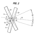
- Fig. 2 which is for a spherical grating having a radius of curvature of 192.4 millimeters
- the grating is shown at two located positions at which the grating will focus dispersed light at the exit slit. In these two positions, the grating is pivoted at plus 31° and minus 11° relative to a reference line R, which is aligned with and perpendicular to the exit slit 23 as shown in Fig. 1.
- the center of the grating is located at a distance of 184.9 millimeters from the exit slit 23 and a distance of 206.9 millimeters (folded by mirror 19) from the entrance slit 17 when the grating is pivoted to its plus 31° degree position.
- Light passing through the entrance slit and reflected from the center of the mirror 29 will impinge on the grating 11 at an angle of 38° to the reference line R.
- the center of the spherical grating is positioned at point A. In this position, the center wavelength of the dispersed light passing through the exit slit is at 2500 nanometers.
- the center of the spherical surface of the grating will be at point B.
- the center wavelength of the dispersed light passing through the exit slit is at 400 nanometers.
- the grating is pivoted on axis 29, to make the center of the grating surface shift from point A to point B on arc 31 and to pivot the grating from its angular position of plus 31° at point A to its angular position of minus 11° at point B.
- the axis 29 is located 9.0 millimeters below the reference line R and 4.0 millimeters behind a line perpendicular to the reference line R and passing through the point A. With the grating pivoted on axis 29, the dispersed light passing through the exit slit 23 will be substantially focused for the entire range from 2500 nanometer to 400 nanometers. This effect is shown by Table I below: wavelength in nanometers bandwidth of prior art grating bandwidth of grating of invention 945 15.49 10.17 1392 10.82 10.33 2290 9.82 10.44 By getting the light focused at the exit slit, a narrower bandwidth of light is transmitted through the exit slit.
- Table I shows the bandwidth at each of three center wavelengths, 945 nanometers, 1392 nanometers and 2290 nanometers. At these three wavelengths with the axis of rotation tangent to the center of the sphere of the grating surface, the bandwidth achieved is shown under the heading "bandwidth of prior art grating". The bandwidth achieved at each of the these wavelengths with the axis of rotation of the grating shifted as shown in Fig. 2 is shown under the heading "bandwidth of invention grating.” The limit of the bandwidth is measured by the wavelengths at which the intensity drops to 1 ⁇ 2 the peak intensity. Thus, it is apparent that a bandwidth of just over ten nanometers is achieved by the system of the invention throughout the spectrum.
- the grating 11 is mounted in a holder 41 which is provided with a bore 43 to engage and receive the axle 14.
- the holder 41 is provided with a slot 45 bisecting the bore 43 to define two plates on each side of the slot 47.
- Screws 47 are passed through bores in one of the two plates defining the slot 45 and are threaded into the other one of the plates to clamp the plates onto the axle 14 to firmly hold the grating in a fixed angular position on the axle 14.
- the bore 43 is positioned to locate the axis 29 on which the grating is rotated at the selected position as show in Fig. 2.
- the weight is distributed in the holder 41 so that the center of gravity of the combined structure of the grating 11 including its substrate, and the holder 41 is on the axis of the axle 14 and therefore is on the axis on which the grating 11 is oscillated.
- the holder 41 has a back portion 48 to engage the back of the grating 11 and a front plate 49 which is screwed onto the back portion 47 by screws 51 to define an arcuate slot to receive the rim of the grating 11.
- the plate 51 has an inwardly projecting tab 53 at its distal end relative to the bore 43 to engage a small part of the front surface grating to ensure that the grating is held in place as it oscillates.
- the specific embodiment of the invention employs a spherical holographic grating, but any grating which focuses the dispersed light at the exit slit may be used.
- the specific technique of locating the axis to pivot the grating involves locating the grating position for focusing the dispersed light at the two extremes of the scanning range of the grating, but it will be apparent that the axis can be determined from any two focusing positions for widely separated wavelengths in the scanning range.
Landscapes
- Physics & Mathematics (AREA)
- Spectroscopy & Molecular Physics (AREA)
- General Physics & Mathematics (AREA)
- Spectrometry And Color Measurement (AREA)
Applications Claiming Priority (2)
| Application Number | Priority Date | Filing Date | Title |
|---|---|---|---|
| US146424 | 1998-09-03 | ||
| US09/146,424 US6031608A (en) | 1998-09-03 | 1998-09-03 | Spectroscopic instrument with offset grating to improve focus |
Publications (2)
| Publication Number | Publication Date |
|---|---|
| EP0984253A2 true EP0984253A2 (de) | 2000-03-08 |
| EP0984253A3 EP0984253A3 (de) | 2000-11-15 |
Family
ID=22517300
Family Applications (1)
| Application Number | Title | Priority Date | Filing Date |
|---|---|---|---|
| EP99115928A Withdrawn EP0984253A3 (de) | 1998-09-03 | 1999-08-13 | Spektroskopisches Instrument mit verschobenem Gitter |
Country Status (4)
| Country | Link |
|---|---|
| US (1) | US6031608A (de) |
| EP (1) | EP0984253A3 (de) |
| JP (1) | JP2000088648A (de) |
| CA (1) | CA2279906C (de) |
Cited By (1)
| Publication number | Priority date | Publication date | Assignee | Title |
|---|---|---|---|---|
| WO2010114466A1 (en) * | 2009-03-30 | 2010-10-07 | Ge Healthcare Bio-Sciences Ab | Holder for a holographic grating |
Families Citing this family (7)
| Publication number | Priority date | Publication date | Assignee | Title |
|---|---|---|---|---|
| US6751576B2 (en) | 2000-03-10 | 2004-06-15 | Cognis Corporation | On-site agricultural product analysis system and method of analyzing |
| US7194369B2 (en) * | 2001-07-23 | 2007-03-20 | Cognis Corporation | On-site analysis system with central processor and method of analyzing |
| US6636305B2 (en) | 2001-09-13 | 2003-10-21 | New Chromex, Inc. | Apparatus and method for producing a substantially straight instrument image |
| US20050097021A1 (en) * | 2003-11-03 | 2005-05-05 | Martin Behr | Object analysis apparatus |
| AU2006200712B1 (en) * | 2006-02-21 | 2006-09-28 | Rosewood Research Pty Ltd | Spectographic sample monitoring |
| KR101619143B1 (ko) * | 2015-12-15 | 2016-05-10 | 동우옵트론 주식회사 | 콘케이브형 회절격자의 최적화 방법을 이용한 혼합시료 분석시스템 |
| CN106197664A (zh) * | 2016-06-30 | 2016-12-07 | 杭州泽天科技有限公司 | 光学分光装置及其调节方法 |
Citations (1)
| Publication number | Priority date | Publication date | Assignee | Title |
|---|---|---|---|---|
| US2948184A (en) * | 1957-07-03 | 1960-08-09 | Gen Electric | Concave grating spectrographic instrument |
Family Cites Families (10)
| Publication number | Priority date | Publication date | Assignee | Title |
|---|---|---|---|---|
| US3658424A (en) * | 1971-01-14 | 1972-04-25 | Spectra Metrics Inc | Method of focusing the horizontal and vertical components from an echelle grating |
| US4264205A (en) * | 1977-08-16 | 1981-04-28 | Neotec Corporation | Rapid scan spectral analysis system utilizing higher order spectral reflections of holographic diffraction gratings |
| US4436393A (en) * | 1983-01-03 | 1984-03-13 | Minnesota Mining And Manufacturing Company | Distortion correction for an overhead projector system |
| JPH01128009A (ja) * | 1987-11-12 | 1989-05-19 | Matsushita Electric Ind Co Ltd | 光チューナ |
| US5015069A (en) * | 1989-02-17 | 1991-05-14 | Linear Instruments | Off axis rotation of diffraction grating |
| CA2035224A1 (en) * | 1990-01-30 | 1991-07-31 | Thornton Stearns | Multispectral reflectometer |
| USH1152H (en) * | 1990-09-27 | 1993-03-02 | United States Of America | Imaging channeled spectrograph |
| US5355188A (en) * | 1993-09-09 | 1994-10-11 | In Focus Systems, Inc. | Method and apparatus for distortion correction in optical projectors |
| JP3254932B2 (ja) * | 1994-09-30 | 2002-02-12 | 安藤電気株式会社 | 光スペクトル測定装置 |
| JPH09210781A (ja) * | 1996-01-31 | 1997-08-15 | Ando Electric Co Ltd | 分光装置 |
-
1998
- 1998-09-03 US US09/146,424 patent/US6031608A/en not_active Expired - Fee Related
-
1999
- 1999-08-13 EP EP99115928A patent/EP0984253A3/de not_active Withdrawn
- 1999-08-19 CA CA002279906A patent/CA2279906C/en not_active Expired - Fee Related
- 1999-08-31 JP JP11246179A patent/JP2000088648A/ja active Pending
Patent Citations (1)
| Publication number | Priority date | Publication date | Assignee | Title |
|---|---|---|---|---|
| US2948184A (en) * | 1957-07-03 | 1960-08-09 | Gen Electric | Concave grating spectrographic instrument |
Non-Patent Citations (4)
| Title |
|---|
| LILLER W.: "Concave Gratings for Astronomical Spectrographs and Spectrometers", APPLIED OPTICS, vol. 2, no. 2, 1 February 1963 (1963-02-01), OSA, OPTICAL SOCIETY OF AMERICA, WASHINGTON, DC, pages 187 - 192, XP007904865 * |
| NAMIOKA T.: "Design of High-Resolution Monochromator for the Vacuum Ultraviolet. An Application of Off-Plane Eagle Mounting", JOURNAL OF THE OPTICAL SOCIETY OF AMERICA, vol. 49, no. 10, 1 October 1959 (1959-10-01), OPTICAL SOCIETY OF AMERICA, US, pages 961 - 965, XP007904868 * |
| NAMIOKA T.: "Theory of the Concave Grating. I", JOURNAL OF THE OPTICAL SOCIETY OF AMERICA, vol. 49, no. 5, 1 May 1959 (1959-05-01), OPTICAL SOCIETY OF AMERICA, US, pages 446 - 460, XP007904867 * |
| SCHROEDER D.: "Scanning Spectrometer of the Gillieson Type", APPLIED OPTICS,, vol. 5, no. 4, 1 April 1966 (1966-04-01), OSA, OPTICAL SOCIETY OF AMERICA, WASHINGTON, DC, pages 545 - 548, XP007904866 * |
Cited By (2)
| Publication number | Priority date | Publication date | Assignee | Title |
|---|---|---|---|---|
| WO2010114466A1 (en) * | 2009-03-30 | 2010-10-07 | Ge Healthcare Bio-Sciences Ab | Holder for a holographic grating |
| US8857779B2 (en) | 2009-03-30 | 2014-10-14 | Ge Healthcare Bio-Sciences Ab | Holder for a holographic grating |
Also Published As
| Publication number | Publication date |
|---|---|
| CA2279906A1 (en) | 2000-03-03 |
| EP0984253A3 (de) | 2000-11-15 |
| JP2000088648A (ja) | 2000-03-31 |
| US6031608A (en) | 2000-02-29 |
| CA2279906C (en) | 2008-10-28 |
Similar Documents
| Publication | Publication Date | Title |
|---|---|---|
| US4932779A (en) | Color measuring instrument with integrating sphere | |
| US4886355A (en) | Combined gloss and color measuring instrument | |
| CA1103074A (en) | Holographic diffraction grating system for rapid scan spectral analysis | |
| US4082464A (en) | Optical analysis system having rotating filters | |
| US6184984B1 (en) | System for measuring polarimetric spectrum and other properties of a sample | |
| US4264205A (en) | Rapid scan spectral analysis system utilizing higher order spectral reflections of holographic diffraction gratings | |
| US5106196A (en) | Single adjustment specular reflection accessory for spectroscopy | |
| EP1063512B1 (de) | Verfahren und Vorrichtung zur Bestimmung von Teilchen unter Benutzung der Reflexion eines mehrfachabtastenden Strahls | |
| US4487504A (en) | Reflectance measuring instrument with integrating sphere | |
| US6982794B1 (en) | Directional reflectometer | |
| CA2279906C (en) | Spectroscopic instrument with offset grating to improve focus | |
| US5699156A (en) | Spectrophotometer apparatus with dual light sources and optical paths, fiber optic pick-up and sample cell therefor | |
| US4989932A (en) | Multiplexer for use with a device for optically analyzing a sample | |
| EP1084379B1 (de) | Optoelektronische Formerfassung durch chromatische Kodierung mit Beleuchtungsebenen | |
| CN106556568A (zh) | 利用衰减全反射的红外光谱仪和扫描仪 | |
| US6414311B1 (en) | Spectrometer accessory for carrying out attenuated total reflectance measurements | |
| US4972092A (en) | Apparatus for determining the effective surface roughness of polished optical samples by measuring the integral scattered radiation | |
| USRE32598E (en) | Feature extraction system for extracting a predetermined feature from a signal | |
| US20010055113A1 (en) | Spectral analysis system with moving objective lens | |
| EP3830553B1 (de) | Vorrichtung für diffuse reflektanz | |
| US5949534A (en) | Goniometric scanning radiometer | |
| US7224460B2 (en) | Mapping-measurement apparatus | |
| US4605306A (en) | Grating monochromator | |
| US6310348B1 (en) | Spectroscopic accessory for examining films and coatings on solid surfaces | |
| JP3871415B2 (ja) | 分光透過率測定装置 |
Legal Events
| Date | Code | Title | Description |
|---|---|---|---|
| PUAI | Public reference made under article 153(3) epc to a published international application that has entered the european phase |
Free format text: ORIGINAL CODE: 0009012 |
|
| AK | Designated contracting states |
Kind code of ref document: A2 Designated state(s): DE FR GB IT |
|
| AX | Request for extension of the european patent |
Free format text: AL;LT;LV;MK;RO;SI |
|
| PUAL | Search report despatched |
Free format text: ORIGINAL CODE: 0009013 |
|
| RIC1 | Information provided on ipc code assigned before grant |
Free format text: 7G 01J 3/18 A, 7G 01J 3/06 B |
|
| AK | Designated contracting states |
Kind code of ref document: A3 Designated state(s): AT BE CH CY DE DK ES FI FR GB GR IE IT LI LU MC NL PT SE |
|
| AX | Request for extension of the european patent |
Free format text: AL;LT;LV;MK;RO;SI |
|
| 17P | Request for examination filed |
Effective date: 20010504 |
|
| AKX | Designation fees paid |
Free format text: DE FR GB IT |
|
| 17Q | First examination report despatched |
Effective date: 20040204 |
|
| 17Q | First examination report despatched |
Effective date: 20040204 |
|
| RAP1 | Party data changed (applicant data changed or rights of an application transferred) |
Owner name: FOSS NIRSYSTEMS, INC. |
|
| STAA | Information on the status of an ep patent application or granted ep patent |
Free format text: STATUS: THE APPLICATION IS DEEMED TO BE WITHDRAWN |
|
| 18D | Application deemed to be withdrawn |
Effective date: 20081021 |