EP0983790B1 - Hot gas reactor and process for using same - Google Patents
Hot gas reactor and process for using same Download PDFInfo
- Publication number
- EP0983790B1 EP0983790B1 EP99117339A EP99117339A EP0983790B1 EP 0983790 B1 EP0983790 B1 EP 0983790B1 EP 99117339 A EP99117339 A EP 99117339A EP 99117339 A EP99117339 A EP 99117339A EP 0983790 B1 EP0983790 B1 EP 0983790B1
- Authority
- EP
- European Patent Office
- Prior art keywords
- reactant
- mixing chamber
- reactant gas
- reaction
- gas
- Prior art date
- Legal status (The legal status is an assumption and is not a legal conclusion. Google has not performed a legal analysis and makes no representation as to the accuracy of the status listed.)
- Expired - Lifetime
Links
- 238000000034 method Methods 0.000 title claims description 26
- 239000000376 reactant Substances 0.000 claims description 100
- 238000006243 chemical reaction Methods 0.000 claims description 82
- 238000002156 mixing Methods 0.000 claims description 77
- 239000007789 gas Substances 0.000 claims description 74
- QVGXLLKOCUKJST-UHFFFAOYSA-N atomic oxygen Chemical compound [O] QVGXLLKOCUKJST-UHFFFAOYSA-N 0.000 claims description 31
- 229910052760 oxygen Inorganic materials 0.000 claims description 31
- 239000001301 oxygen Substances 0.000 claims description 31
- 239000000203 mixture Substances 0.000 claims description 16
- 229930195733 hydrocarbon Natural products 0.000 claims description 14
- 150000002430 hydrocarbons Chemical class 0.000 claims description 14
- 239000004215 Carbon black (E152) Substances 0.000 claims description 12
- 239000012808 vapor phase Substances 0.000 claims description 11
- 238000010438 heat treatment Methods 0.000 claims description 6
- 238000004519 manufacturing process Methods 0.000 claims description 5
- 239000000126 substance Substances 0.000 claims description 4
- UGFAIRIUMAVXCW-UHFFFAOYSA-N Carbon monoxide Chemical compound [O+]#[C-] UGFAIRIUMAVXCW-UHFFFAOYSA-N 0.000 claims description 3
- 239000001257 hydrogen Substances 0.000 claims description 3
- 229910052739 hydrogen Inorganic materials 0.000 claims description 3
- ZAMOUSCENKQFHK-UHFFFAOYSA-N Chlorine atom Chemical compound [Cl] ZAMOUSCENKQFHK-UHFFFAOYSA-N 0.000 claims description 2
- PXGOKWXKJXAPGV-UHFFFAOYSA-N Fluorine Chemical compound FF PXGOKWXKJXAPGV-UHFFFAOYSA-N 0.000 claims description 2
- 229910002091 carbon monoxide Inorganic materials 0.000 claims description 2
- 239000000460 chlorine Substances 0.000 claims description 2
- 229910052801 chlorine Inorganic materials 0.000 claims description 2
- 239000011737 fluorine Substances 0.000 claims description 2
- 229910052731 fluorine Inorganic materials 0.000 claims description 2
- 239000011261 inert gas Substances 0.000 claims description 2
- 125000004435 hydrogen atom Chemical class [H]* 0.000 claims 1
- ATUOYWHBWRKTHZ-UHFFFAOYSA-N Propane Chemical compound CCC ATUOYWHBWRKTHZ-UHFFFAOYSA-N 0.000 description 20
- 230000003197 catalytic effect Effects 0.000 description 17
- 238000013461 design Methods 0.000 description 13
- VNWKTOKETHGBQD-UHFFFAOYSA-N methane Chemical compound C VNWKTOKETHGBQD-UHFFFAOYSA-N 0.000 description 12
- 239000001294 propane Substances 0.000 description 10
- 239000003054 catalyst Substances 0.000 description 9
- 238000007254 oxidation reaction Methods 0.000 description 8
- 239000000047 product Substances 0.000 description 8
- 238000011065 in-situ storage Methods 0.000 description 7
- XKRFYHLGVUSROY-UHFFFAOYSA-N Argon Chemical compound [Ar] XKRFYHLGVUSROY-UHFFFAOYSA-N 0.000 description 6
- XLYOFNOQVPJJNP-UHFFFAOYSA-N water Substances O XLYOFNOQVPJJNP-UHFFFAOYSA-N 0.000 description 6
- IJGRMHOSHXDMSA-UHFFFAOYSA-N Atomic nitrogen Chemical compound N#N IJGRMHOSHXDMSA-UHFFFAOYSA-N 0.000 description 5
- CURLTUGMZLYLDI-UHFFFAOYSA-N Carbon dioxide Chemical compound O=C=O CURLTUGMZLYLDI-UHFFFAOYSA-N 0.000 description 5
- 239000003085 diluting agent Substances 0.000 description 5
- 230000003647 oxidation Effects 0.000 description 5
- 239000002245 particle Substances 0.000 description 5
- QGZKDVFQNNGYKY-UHFFFAOYSA-N Ammonia Chemical compound N QGZKDVFQNNGYKY-UHFFFAOYSA-N 0.000 description 4
- MYMOFIZGZYHOMD-UHFFFAOYSA-N Dioxygen Chemical compound O=O MYMOFIZGZYHOMD-UHFFFAOYSA-N 0.000 description 4
- 239000012530 fluid Substances 0.000 description 4
- LELOWRISYMNNSU-UHFFFAOYSA-N hydrogen cyanide Chemical compound N#C LELOWRISYMNNSU-UHFFFAOYSA-N 0.000 description 4
- FPYJFEHAWHCUMM-UHFFFAOYSA-N maleic anhydride Chemical compound O=C1OC(=O)C=C1 FPYJFEHAWHCUMM-UHFFFAOYSA-N 0.000 description 4
- 239000011541 reaction mixture Substances 0.000 description 4
- 229910052786 argon Inorganic materials 0.000 description 3
- 230000015572 biosynthetic process Effects 0.000 description 3
- 239000001273 butane Substances 0.000 description 3
- 229910002092 carbon dioxide Inorganic materials 0.000 description 3
- UBAZGMLMVVQSCD-UHFFFAOYSA-N carbon dioxide;molecular oxygen Chemical compound O=O.O=C=O UBAZGMLMVVQSCD-UHFFFAOYSA-N 0.000 description 3
- 238000002485 combustion reaction Methods 0.000 description 3
- 238000010276 construction Methods 0.000 description 3
- 229910001882 dioxygen Inorganic materials 0.000 description 3
- IJDNQMDRQITEOD-UHFFFAOYSA-N n-butane Chemical compound CCCC IJDNQMDRQITEOD-UHFFFAOYSA-N 0.000 description 3
- OFBQJSOFQDEBGM-UHFFFAOYSA-N n-pentane Natural products CCCCC OFBQJSOFQDEBGM-UHFFFAOYSA-N 0.000 description 3
- 239000007787 solid Substances 0.000 description 3
- NLHHRLWOUZZQLW-UHFFFAOYSA-N Acrylonitrile Chemical compound C=CC#N NLHHRLWOUZZQLW-UHFFFAOYSA-N 0.000 description 2
- IAYPIBMASNFSPL-UHFFFAOYSA-N Ethylene oxide Chemical compound C1CO1 IAYPIBMASNFSPL-UHFFFAOYSA-N 0.000 description 2
- MWUXSHHQAYIFBG-UHFFFAOYSA-N Nitric oxide Chemical compound O=[N] MWUXSHHQAYIFBG-UHFFFAOYSA-N 0.000 description 2
- GWEVSGVZZGPLCZ-UHFFFAOYSA-N Titan oxide Chemical compound O=[Ti]=O GWEVSGVZZGPLCZ-UHFFFAOYSA-N 0.000 description 2
- 229910021529 ammonia Inorganic materials 0.000 description 2
- 238000004364 calculation method Methods 0.000 description 2
- 239000001569 carbon dioxide Substances 0.000 description 2
- 239000013626 chemical specie Substances 0.000 description 2
- 230000003247 decreasing effect Effects 0.000 description 2
- 239000002638 heterogeneous catalyst Substances 0.000 description 2
- 239000008240 homogeneous mixture Substances 0.000 description 2
- NNPPMTNAJDCUHE-UHFFFAOYSA-N isobutane Chemical compound CC(C)C NNPPMTNAJDCUHE-UHFFFAOYSA-N 0.000 description 2
- 239000003345 natural gas Substances 0.000 description 2
- 229910052757 nitrogen Inorganic materials 0.000 description 2
- 230000035484 reaction time Effects 0.000 description 2
- 239000011949 solid catalyst Substances 0.000 description 2
- 230000006641 stabilisation Effects 0.000 description 2
- 238000011105 stabilization Methods 0.000 description 2
- 238000010977 unit operation Methods 0.000 description 2
- 238000011144 upstream manufacturing Methods 0.000 description 2
- SMZOUWXMTYCWNB-UHFFFAOYSA-N 2-(2-methoxy-5-methylphenyl)ethanamine Chemical compound COC1=CC=C(C)C=C1CCN SMZOUWXMTYCWNB-UHFFFAOYSA-N 0.000 description 1
- NIXOWILDQLNWCW-UHFFFAOYSA-N 2-Propenoic acid Natural products OC(=O)C=C NIXOWILDQLNWCW-UHFFFAOYSA-N 0.000 description 1
- OKTJSMMVPCPJKN-UHFFFAOYSA-N Carbon Chemical compound [C] OKTJSMMVPCPJKN-UHFFFAOYSA-N 0.000 description 1
- OTMSDBZUPAUEDD-UHFFFAOYSA-N Ethane Chemical compound CC OTMSDBZUPAUEDD-UHFFFAOYSA-N 0.000 description 1
- VGGSQFUCUMXWEO-UHFFFAOYSA-N Ethene Chemical compound C=C VGGSQFUCUMXWEO-UHFFFAOYSA-N 0.000 description 1
- 239000005977 Ethylene Substances 0.000 description 1
- UFHFLCQGNIYNRP-UHFFFAOYSA-N Hydrogen Chemical compound [H][H] UFHFLCQGNIYNRP-UHFFFAOYSA-N 0.000 description 1
- YZCKVEUIGOORGS-UHFFFAOYSA-N Hydrogen atom Chemical compound [H] YZCKVEUIGOORGS-UHFFFAOYSA-N 0.000 description 1
- VQTUBCCKSQIDNK-UHFFFAOYSA-N Isobutene Chemical group CC(C)=C VQTUBCCKSQIDNK-UHFFFAOYSA-N 0.000 description 1
- 241000321453 Paranthias colonus Species 0.000 description 1
- LGRFSURHDFAFJT-UHFFFAOYSA-N Phthalic anhydride Natural products C1=CC=C2C(=O)OC(=O)C2=C1 LGRFSURHDFAFJT-UHFFFAOYSA-N 0.000 description 1
- XTXRWKRVRITETP-UHFFFAOYSA-N Vinyl acetate Chemical compound CC(=O)OC=C XTXRWKRVRITETP-UHFFFAOYSA-N 0.000 description 1
- ATRMIFNAYHCLJR-UHFFFAOYSA-N [O].CCC Chemical compound [O].CCC ATRMIFNAYHCLJR-UHFFFAOYSA-N 0.000 description 1
- 238000011021 bench scale process Methods 0.000 description 1
- JHIWVOJDXOSYLW-UHFFFAOYSA-N butyl 2,2-difluorocyclopropane-1-carboxylate Chemical compound CCCCOC(=O)C1CC1(F)F JHIWVOJDXOSYLW-UHFFFAOYSA-N 0.000 description 1
- 239000006227 byproduct Substances 0.000 description 1
- 229910052799 carbon Inorganic materials 0.000 description 1
- 239000006229 carbon black Substances 0.000 description 1
- 229910002090 carbon oxide Inorganic materials 0.000 description 1
- 238000007084 catalytic combustion reaction Methods 0.000 description 1
- 238000006555 catalytic reaction Methods 0.000 description 1
- 239000007795 chemical reaction product Substances 0.000 description 1
- 239000003245 coal Substances 0.000 description 1
- 238000009841 combustion method Methods 0.000 description 1
- 230000000052 comparative effect Effects 0.000 description 1
- 238000004590 computer program Methods 0.000 description 1
- 230000008602 contraction Effects 0.000 description 1
- 238000001816 cooling Methods 0.000 description 1
- 230000007423 decrease Effects 0.000 description 1
- 238000006356 dehydrogenation reaction Methods 0.000 description 1
- 238000010586 diagram Methods 0.000 description 1
- 238000005516 engineering process Methods 0.000 description 1
- 238000004880 explosion Methods 0.000 description 1
- 239000000446 fuel Substances 0.000 description 1
- 238000010574 gas phase reaction Methods 0.000 description 1
- 239000013529 heat transfer fluid Substances 0.000 description 1
- 239000001307 helium Substances 0.000 description 1
- 229910052734 helium Inorganic materials 0.000 description 1
- SWQJXJOGLNCZEY-UHFFFAOYSA-N helium atom Chemical compound [He] SWQJXJOGLNCZEY-UHFFFAOYSA-N 0.000 description 1
- 150000002431 hydrogen Chemical class 0.000 description 1
- 230000000977 initiatory effect Effects 0.000 description 1
- 238000002347 injection Methods 0.000 description 1
- 239000007924 injection Substances 0.000 description 1
- 239000001282 iso-butane Substances 0.000 description 1
- 238000012423 maintenance Methods 0.000 description 1
- 239000000463 material Substances 0.000 description 1
- 229910044991 metal oxide Inorganic materials 0.000 description 1
- 150000004706 metal oxides Chemical class 0.000 description 1
- 229960003753 nitric oxide Drugs 0.000 description 1
- JCXJVPUVTGWSNB-UHFFFAOYSA-N nitrogen dioxide Inorganic materials O=[N]=O JCXJVPUVTGWSNB-UHFFFAOYSA-N 0.000 description 1
- 239000007800 oxidant agent Substances 0.000 description 1
- 230000001590 oxidative effect Effects 0.000 description 1
- 238000011027 product recovery Methods 0.000 description 1
- -1 propylene, butylene Chemical group 0.000 description 1
- 238000007348 radical reaction Methods 0.000 description 1
- 238000011084 recovery Methods 0.000 description 1
- 238000002407 reforming Methods 0.000 description 1
- 238000011160 research Methods 0.000 description 1
- 238000000926 separation method Methods 0.000 description 1
- 241000894007 species Species 0.000 description 1
- 238000005507 spraying Methods 0.000 description 1
- 238000004227 thermal cracking Methods 0.000 description 1
- 239000010409 thin film Substances 0.000 description 1
- 239000004408 titanium dioxide Substances 0.000 description 1
- XJDNKRIXUMDJCW-UHFFFAOYSA-J titanium tetrachloride Chemical compound Cl[Ti](Cl)(Cl)Cl XJDNKRIXUMDJCW-UHFFFAOYSA-J 0.000 description 1
Images


Classifications
-
- B—PERFORMING OPERATIONS; TRANSPORTING
- B01—PHYSICAL OR CHEMICAL PROCESSES OR APPARATUS IN GENERAL
- B01J—CHEMICAL OR PHYSICAL PROCESSES, e.g. CATALYSIS OR COLLOID CHEMISTRY; THEIR RELEVANT APPARATUS
- B01J12/00—Chemical processes in general for reacting gaseous media with gaseous media; Apparatus specially adapted therefor
- B01J12/007—Chemical processes in general for reacting gaseous media with gaseous media; Apparatus specially adapted therefor in the presence of catalytically active bodies, e.g. porous plates
-
- B—PERFORMING OPERATIONS; TRANSPORTING
- B01—PHYSICAL OR CHEMICAL PROCESSES OR APPARATUS IN GENERAL
- B01J—CHEMICAL OR PHYSICAL PROCESSES, e.g. CATALYSIS OR COLLOID CHEMISTRY; THEIR RELEVANT APPARATUS
- B01J12/00—Chemical processes in general for reacting gaseous media with gaseous media; Apparatus specially adapted therefor
-
- B—PERFORMING OPERATIONS; TRANSPORTING
- B01—PHYSICAL OR CHEMICAL PROCESSES OR APPARATUS IN GENERAL
- B01J—CHEMICAL OR PHYSICAL PROCESSES, e.g. CATALYSIS OR COLLOID CHEMISTRY; THEIR RELEVANT APPARATUS
- B01J12/00—Chemical processes in general for reacting gaseous media with gaseous media; Apparatus specially adapted therefor
- B01J12/005—Chemical processes in general for reacting gaseous media with gaseous media; Apparatus specially adapted therefor carried out at high temperatures, e.g. by pyrolysis
-
- B—PERFORMING OPERATIONS; TRANSPORTING
- B01—PHYSICAL OR CHEMICAL PROCESSES OR APPARATUS IN GENERAL
- B01J—CHEMICAL OR PHYSICAL PROCESSES, e.g. CATALYSIS OR COLLOID CHEMISTRY; THEIR RELEVANT APPARATUS
- B01J3/00—Processes of utilising sub-atmospheric or super-atmospheric pressure to effect chemical or physical change of matter; Apparatus therefor
- B01J3/008—Processes carried out under supercritical conditions
-
- B—PERFORMING OPERATIONS; TRANSPORTING
- B01—PHYSICAL OR CHEMICAL PROCESSES OR APPARATUS IN GENERAL
- B01J—CHEMICAL OR PHYSICAL PROCESSES, e.g. CATALYSIS OR COLLOID CHEMISTRY; THEIR RELEVANT APPARATUS
- B01J3/00—Processes of utilising sub-atmospheric or super-atmospheric pressure to effect chemical or physical change of matter; Apparatus therefor
- B01J3/02—Feed or outlet devices therefor
-
- B—PERFORMING OPERATIONS; TRANSPORTING
- B01—PHYSICAL OR CHEMICAL PROCESSES OR APPARATUS IN GENERAL
- B01J—CHEMICAL OR PHYSICAL PROCESSES, e.g. CATALYSIS OR COLLOID CHEMISTRY; THEIR RELEVANT APPARATUS
- B01J2208/00—Processes carried out in the presence of solid particles; Reactors therefor
- B01J2208/00008—Controlling the process
- B01J2208/00017—Controlling the temperature
- B01J2208/00106—Controlling the temperature by indirect heat exchange
- B01J2208/00265—Part of all of the reactants being heated or cooled outside the reactor while recycling
- B01J2208/00274—Part of all of the reactants being heated or cooled outside the reactor while recycling involving reactant vapours
-
- B—PERFORMING OPERATIONS; TRANSPORTING
- B01—PHYSICAL OR CHEMICAL PROCESSES OR APPARATUS IN GENERAL
- B01J—CHEMICAL OR PHYSICAL PROCESSES, e.g. CATALYSIS OR COLLOID CHEMISTRY; THEIR RELEVANT APPARATUS
- B01J2208/00—Processes carried out in the presence of solid particles; Reactors therefor
- B01J2208/00008—Controlling the process
- B01J2208/00017—Controlling the temperature
- B01J2208/00389—Controlling the temperature using electric heating or cooling elements
-
- B—PERFORMING OPERATIONS; TRANSPORTING
- B01—PHYSICAL OR CHEMICAL PROCESSES OR APPARATUS IN GENERAL
- B01J—CHEMICAL OR PHYSICAL PROCESSES, e.g. CATALYSIS OR COLLOID CHEMISTRY; THEIR RELEVANT APPARATUS
- B01J2208/00—Processes carried out in the presence of solid particles; Reactors therefor
- B01J2208/00008—Controlling the process
- B01J2208/00539—Pressure
-
- B—PERFORMING OPERATIONS; TRANSPORTING
- B01—PHYSICAL OR CHEMICAL PROCESSES OR APPARATUS IN GENERAL
- B01J—CHEMICAL OR PHYSICAL PROCESSES, e.g. CATALYSIS OR COLLOID CHEMISTRY; THEIR RELEVANT APPARATUS
- B01J2208/00—Processes carried out in the presence of solid particles; Reactors therefor
- B01J2208/00008—Controlling the process
- B01J2208/00548—Flow
-
- B—PERFORMING OPERATIONS; TRANSPORTING
- B01—PHYSICAL OR CHEMICAL PROCESSES OR APPARATUS IN GENERAL
- B01J—CHEMICAL OR PHYSICAL PROCESSES, e.g. CATALYSIS OR COLLOID CHEMISTRY; THEIR RELEVANT APPARATUS
- B01J2219/00—Chemical, physical or physico-chemical processes in general; Their relevant apparatus
- B01J2219/00049—Controlling or regulating processes
- B01J2219/00051—Controlling the temperature
- B01J2219/00074—Controlling the temperature by indirect heating or cooling employing heat exchange fluids
- B01J2219/00105—Controlling the temperature by indirect heating or cooling employing heat exchange fluids part or all of the reactants being heated or cooled outside the reactor while recycling
- B01J2219/00108—Controlling the temperature by indirect heating or cooling employing heat exchange fluids part or all of the reactants being heated or cooled outside the reactor while recycling involving reactant vapours
-
- B—PERFORMING OPERATIONS; TRANSPORTING
- B01—PHYSICAL OR CHEMICAL PROCESSES OR APPARATUS IN GENERAL
- B01J—CHEMICAL OR PHYSICAL PROCESSES, e.g. CATALYSIS OR COLLOID CHEMISTRY; THEIR RELEVANT APPARATUS
- B01J2219/00—Chemical, physical or physico-chemical processes in general; Their relevant apparatus
- B01J2219/00049—Controlling or regulating processes
- B01J2219/00051—Controlling the temperature
- B01J2219/00132—Controlling the temperature using electric heating or cooling elements
-
- B—PERFORMING OPERATIONS; TRANSPORTING
- B01—PHYSICAL OR CHEMICAL PROCESSES OR APPARATUS IN GENERAL
- B01J—CHEMICAL OR PHYSICAL PROCESSES, e.g. CATALYSIS OR COLLOID CHEMISTRY; THEIR RELEVANT APPARATUS
- B01J2219/00—Chemical, physical or physico-chemical processes in general; Their relevant apparatus
- B01J2219/00049—Controlling or regulating processes
- B01J2219/00162—Controlling or regulating processes controlling the pressure
-
- B—PERFORMING OPERATIONS; TRANSPORTING
- B01—PHYSICAL OR CHEMICAL PROCESSES OR APPARATUS IN GENERAL
- B01J—CHEMICAL OR PHYSICAL PROCESSES, e.g. CATALYSIS OR COLLOID CHEMISTRY; THEIR RELEVANT APPARATUS
- B01J2219/00—Chemical, physical or physico-chemical processes in general; Their relevant apparatus
- B01J2219/00049—Controlling or regulating processes
- B01J2219/00164—Controlling or regulating processes controlling the flow
-
- Y—GENERAL TAGGING OF NEW TECHNOLOGICAL DEVELOPMENTS; GENERAL TAGGING OF CROSS-SECTIONAL TECHNOLOGIES SPANNING OVER SEVERAL SECTIONS OF THE IPC; TECHNICAL SUBJECTS COVERED BY FORMER USPC CROSS-REFERENCE ART COLLECTIONS [XRACs] AND DIGESTS
- Y02—TECHNOLOGIES OR APPLICATIONS FOR MITIGATION OR ADAPTATION AGAINST CLIMATE CHANGE
- Y02P—CLIMATE CHANGE MITIGATION TECHNOLOGIES IN THE PRODUCTION OR PROCESSING OF GOODS
- Y02P20/00—Technologies relating to chemical industry
- Y02P20/50—Improvements relating to the production of bulk chemicals
- Y02P20/54—Improvements relating to the production of bulk chemicals using solvents, e.g. supercritical solvents or ionic liquids
Definitions
- the invention relates to the field of vapor phase chemical reactions. More particularly, the invention relates to a particular reaction process for such reactions.
- Pre-mixed reactors include fixed catalytic bed, catalytic gauze bed, and catalytic monolith.
- the reactants are separately conveyed to a device which mixes the two streams.
- the residence time within this mixing zone is typically on the order of seconds.
- the reaction mixture can be preheated by providing thermal energy to the mixture or to either one or both of the reactants prior to interacting.
- the uniform mixture flows to a reaction zone where the reaction is initiated.
- the reaction zone contains a heterogeneous catalyst.
- the residence time within the reaction zone is on the order of one second for fixed bed reactors and 0.01 seconds for gauze bed and monolith reactors.
- the reaction is performed homogeneously without the aid of a catalyst.
- the reaction zone may contain an ignition source or some flame stabilization mechanism, and the residence time in the reaction zone is on the order of 0.1 seconds.
- the most common catalytic pre-mixed reactor is a fixed bed reactor.
- a solid catalyst is packed within long tubes which are placed within a circulating heat transfer fluid which is used to remove the heat of reaction.
- Products such as phthalic anhydride, maleic anhydride, acrylic acid, ethylene oxide, and vinyl acetate are made using these reactors.
- Another commercialized catalytic pre-mixed reactor is a gauze reactor.
- the catalyst is a very thin (on the order of a centimeter) bundle of wire mesh through which the reaction mixture flows. No attempt is made to remove the heat of reaction from the catalyst bed. Hydrogen cyanide and nitric oxide are made using this type of reactor.
- a catalytic monolith reactor is a solid porous structure through which gas can flow.
- Catalytic monoliths have been used commercially to perform total oxidation reactions in catalytic combustion and in automotive catalytic converters. Typically with these reactors, no attempt is made to remove the heat of reaction within the reactor itself. Additionally, this type of reactor has been employed at bench scale to perform partial oxidation reactions.
- In-situ mixed reactors include fluid catalytic bed and homogeneous burner reactors.
- the reactants are brought together for the first time within the reactor.
- the major commercial in-situ mixed reactor is a fluid bed reactor.
- the reactants are injected separately into a vessel which contains a large mass of circulating solid particles.
- the reactant gases cause the motion of the solid particles.
- these particles act as catalysts.
- These reactors are typically equipped with internal steam coils to remove the heat of reaction within the reactor.
- the residence time in these reactors is typically on the order of 10 seconds. Examples of products produced in fluid beds include acrylonitrile and maleic anhydride.
- the third class of reactors are indirectly contacted reactors, such as a catalytic transport bed reactor.
- indirect contact reactors the reactants are never actually brought together. Instead, the oxygen source and reactant are isolated from each other in the reactor either spatially or temporally.
- the only known commercial reactor of this type is the transport bed.
- the solid catalyst is conveyed between two different isolated sections of the reactor. One reactant is injected into one section while the second reactant is injected into the other.
- a version of such a reactor has recently been commercialized for the production of maleic anhydride.
- two or more chemically reactive gas streams are compressed in compressors and passed through heaters in the form of fired tubes, and then are supplied to a nozzle array at subsonic velocity and at elevated temperatures such that their average temperature is above reaction temperature.
- the nozzle array provides for subdividing each of the streams into a group of smaller, narrow streams and for accelerating the gas of each narrow stream at supersonic velocity sufficient to cool the gases to below reaction temperature.
- the resultant cooled supersonic streams are discharged in a substantially common direction in closely interspersed relationship into one end of an elongated mixing zone, and are passed through the mixing zone continuously at supersonic velocity and without chemical reaction between the gases thereof, thereby effecting lateral mixing between the narrow streams of different groups during the flow.
- EP-A-0 001 946 discloses an apparatus for mixing very rapidly, without the formation of carbon particles, the reacting gases entering oxygen reforming reactors containing a catalyst and where a highly exothermic redaction occurs instantaneously, before reaching the catalyst, between a free oxygen rich gas and a process gas containing hydrocarbons, and possibly steam hydrogen and carbon oxides.
- the known apparatus comprises a shell containing a distributor and a multitude of parallel channels.
- the shell is provided with one or more conduits through which the process gas is injected tangentially into the shell thereby subjecting it to a helical flow therein.
- the distributor receives the oxygen rich gas.
- the channels are parallel to the axis of the shell and arranged so as to allow the process gas to flow around and between the channels before coming into contact with the oxygen rich gas.
- Each one of these channels is welded at one end to the distributor and open at the other end, so that oxygen rich gas is injected in each channel at one end and issues at the other end, where it comes into contact with the process gas.
- the orifice through which the oxygen rich gas issues from each channel has at least one very reduced dimension, thus allowing to inject each jet of the oxygen rich gas in the form of a thin film or thread and to obtain an essentially homogeneous gas mixture before the partial oxidation reaction proceeds significantly. It is indicated that in industrial praxis it is found advantageous to preheat the reacting gases as much as possible.
- the invention provides for a chemical vapor reaction process as defined in claim 1.
- HGR hot gas reactor
- hot we mean a gas at a temperature greater than 500°C, preferably greater than 530 °C.
- the range of temperatures is 500°C to 2800°C, and more preferably 500°C to 1700°C.
- the first component of the reactor is a source 1 of hot reactant gas (referred to as reactant A).
- Reactant A is preferably oxygen, but is not limited as such.
- a preferred source 1 is via the use of the thermal nozzle combustion method described in U.S. Patent 5,266,024 to Anderson .
- the reactor further comprises a mixing chamber 2 where reactant A and another reactant gas (referred to herein as Reactant B) undergo extremely rapid mixing, but experience substantially no reaction.
- Reactant B another reactant gas
- Reactant A is injected into the mixing chamber 2 as an expanding jet 3 .
- Expanding jet 3 may be formed by placing a restriction 4 (such as a flow nozzle) between the hot gas source 1 and the mixing chamber 2 .
- the absolute pressure of the hot gas before it is injected into the mixing chamber is preferably at least 1.2 times, more preferably at least 1.5 times, and most preferably at least 2 times the absolute pressure in the mixing chamber.
- the pressure in the mixing chamber should preferably range from 200 to 0.01 atmospheres (atm), more preferably 100 to 0.01 atm, and most preferably 10 to 1 atm. All pressures referred to herein are absolute pressures.
- Running the HGR at the pressures described offers at least the following three advantages.
- the first is that there will be improvements in at least one of selectivity, conversion, productivity, and decreased byproduct formation.
- the second is that the reactor can be made smaller for the same mass flow rate, which will keep the mixing times small at very large flow rates and reduce the capital cost of the reactor.
- high pressure operation of the HGR and subsequent discharge of the reaction products at high pressure may allow advantageous operation of unit operations downstream of the HGR. These unit operations include, but are not limited to, additional reaction, product separation, and product recovery.
- Reactant B is injected into the mixing chamber adjacent to the where reactant A is injected by some suitable means 5 such as multiple injection ports preferably arranged perpendicular to the axis of the expanding jet of reactant A.
- the velocity of reactant A is greater than 300 m/s.
- a critical element of the invention is that the use of a hot reactant jet enables the reactants to mix extremely rapidly.
- the contact time of the reactants in the mixing zone is short enough to prevent any significant reaction from occurring in the mixing section. The time required before significant reaction occurs depends on the particular reactants and reaction conditions.
- the contact time of reactant A and reactant B in the mixing chamber should preferably be less than about 10 milliseconds, more preferably less than about 1 millisecond, and most preferably less than about 0.5 milliseconds.
- the mixture of reactant A and Reactant B undergoes a vapor phase reaction in reaction zone 6 .
- the vapor phase reaction may be catalytic and/or non-catalytic.
- the reaction zone is differentiated from the mixing zone by the presence of a catalyst such as a monolith, a packed bed, or a gauze pack.
- a catalyst such as a monolith, a packed bed, or a gauze pack.
- the reaction zone is differentiated from the mixing zone by the presence of a sharp chemical gradient or a flame stabilization device.
- the use of a hot gas stream in the mixing step is critical to this invention.
- the heating of reactant A upstream of the mixing chamber 2 improves the mixing between the reactants in two respects.
- the velocity of the hot gas (Reactant A) entering the mixing chamber 2 increases with an increase in temperature of the hot gas. For example, if reactant A was oxygen provided at 21°C and 1.8 atm and discharged at 1 atm, the exit velocity of the gas from the nozzle 4 would be 290 m/s. In comparison, if the oxygen were heated up to 1090°C , the exit velocity at the same supply pressure would be 625 m/s. Since the rate of gas mixing is a direct function of gas velocity, the advantage of heating reactant A is substantial.
- the amount of mixing between a gas jet (e.g. Reactant A) and an ambient gas (e.g. Reactant B) increases as the density of the jet gas decreases.
- Gas density is inversely proportional to the absolute temperature.
- the amount of entrainment (and thereby mixing) of reactant B into the jet over a given jet length would be doubled as the jet gas temperature increased from 21°C to 904°C.
- the invention differs from prior art reactors, such as pre-mixed non-catalytic reactors, in that the mixing in the mixing chamber 2 takes place under reactive conditions.
- the invention differs from prior art reactors, such as in situ -mixed non-catalytic reactors, in that a substantially homogeneous mixture of reactants is formed within the mixing chamber 2 before any substantial reaction occurs.
- the rapid rate of mixing allows for a substantially homogeneous mixture to be formed within the mixing chamber 2 prior to the initiation of substantial reaction even though the mixing occurs under reactive conditions.
- the HGR allows for the mixing of reactants without the need for diluent (e.g. ballast gas).
- the invention has been reduced to practice by reacting a hot oxygen stream with hydrocarbon in a small scale HGR.
- the hot oxygen stream was obtained by continuously burning a small amount of fuel using a thermal nozzle as described in U.S. Patent 5,266,024 .
- the laboratory mixing chamber design had four equally spaced feed gas inlets located near the hot oxygen entrance nozzle.
- the mixing chamber was tube approximately 9 cm long and 1.9 cm in diameter, and had no internal baffles.
- the reaction zone was the same diameter as the diameter of the mixing zone, thus allowing for very simple construction. This also allowed the reaction mixture stream to be delivered to the reaction zone with a nearly uniform velocity profile.
- the laboratory HGR employed heterogeneous catalysts in the reaction zone.
- Table 1 presents calculated results for the entrainment of methane into a hot oxygen jet for a 0.16 cm jet diameter and a 10:1 methane to oxygen ratio, wherein the first and second column refer to comparative examples and the third column applies to the process of the present invention.
- the data shows that the expected mixing time achieved with the laboratory HGR is on the order of 0.2 msec or less. Temperature (°C) 27 1,650 1,650 Velocity (m/s) 300 300 760 Jet Length (cm) 3.5 1.4 1.4 Mixing Time (s) 0.4 0.16 0.06
- Figure 2 is an experimental gas concentration profile observed in the laboratory HGR at the end of the mixing chamber.
- approximately 11 standard liters per minute (SLPM) of natural gas and approximately 137 SLPM of oxygen were routed to a thermal nozzle (see US 5,266,024 ) where all the natural gas was completely combusted to produce a hot reactant oxygen stream containing approximately 115 SLPM of oxygen, 11 SLPM of carbon dioxide, and 22 SLPM of water vapor.
- This mixture served as the hot reactant A for the HGR.
- Figure 2 shows the concentrations of oxygen, carbon dioxide and water vapor as measured at the exit of the mixing chamber at five different points along the diameter of the mixing chamber.
- the calculated concentrations of propane as derived from a species balance are also shown in Figure 2. No other chemical species were detected.
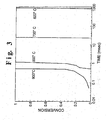
- Figure 3 illustrates that under many conditions no appreciable homogeneous reaction occurs in the HGR mixing chamber.
- the "Thermochemistry Calculator” available from the California Institute of Technology and based on CHEMKIN (a computer program developed by Sandia Livermore National Laboratory to calculate known homogeneous reaction kinetics) was used to calculate the fraction percent of propane reacted versus time for several different oxygen-propane mixtures.
- Konnov Detailed reaction mechanism for small hydrocarbons combustion. Release 0.1 http://homepages.vub.ac.be/ ⁇ akonnov/, 1996) was used.
- the initial composition of each different reaction mixture was set at the stoichiometric ratio for the production of CO, e.g. 2:3 propane:oxygen.
- the initial temperature was calculated by assuming complete and instantaneous mixing between oxygen at the temperatures indicated in Figure 3 and propane at 25°C.
- the residence time within the mixing zone will be less than 0.5 milliseconds (msec).
- Table 2 lists the operating limits for the vapor phase partial oxidation of butane to maleic anhydride (a process for which all three commercial catalytic reactor types have been used) for conventional reactor design and the HGR. Laboratory data for the oxidation of butane over a monolith reactor is also included. This table demonstrates the greater range of operating conditions achievable with the HGR as compared to conventional technology. Table 2. Comparison of HGR with conventional heterogeneous reactor designs.
- the HGR allows for the safe reaction of feed and reactant gas (e.g. oxygen) at concentrations, temperatures, and pressures that were previously unattainable due to flammability risk.
- feed and reactant gas e.g. oxygen
- the HGR allows for the use of oxygen without a diluent, thus resulting in reducing the size and improving the efficiency of downstream recovery operations and in greatly reducing the volume of the process tailstream.
- the reactants are pre-mixed under non-reactive conditions and then transported to a reaction zone where the conditions are such to initiate reaction.
- a reaction zone where the conditions are such to initiate reaction.
- either very complicated mixing chamber designs must be employed or the feed concentrations, temperature, and pressure must be such that reaction cannot occur.
- Complicated mixing chamber designs are undesirable because of their high associated construction costs. Limiting the feed conditions is undesirable because this leads to lower selectivities and capacity. Additionally undesired reactions can occur as the reactant mix is raised to the reaction temperature.
- the HGR avoids all of these problems.
- the mixing chamber is quite simple. The reactants can be safely mixed under a broader set of conditions, and reaction is suppressed until the reactants are well mixed and at the optimum reaction conditions.
- the HGR eliminates shortcomings associated with homogeneous in-situ mixed systems. By completely mixing the reactants before they undergo any reaction, the reaction time and reactant concentration are very well defined. Thus the reactor is operated under optimal conditions without experiencing variability in product yield, selectivity, and quality. Further, due to the fast mixing of reactants, flammability hazards are reduced.
- the design of the HGR is quite simple. This simplicity in design will make the engineering, construction, and maintenance of a commercial HGR reactor significantly less expensive than that of conventional reactors, both homogeneous and heterogeneous.
- the HGR can be used for a variety of chemical reactions, including currently performed vapor phase reactions as well as reactions which are not currently performed commercially. Examples include, but are not limited to: dehydrogenation reactions, production of syn-gas, ammoxidations, ammonia oxidation, selective free-radical reactions, formation of carbon black and metal oxide particle production, and thermal cracking with atomic hydrogen.
- the first hot gas may include inert gases (i.e. argon, helium, nitrogen, and carbon dioxide), or other gases such as hydrogen, carbon monoxide, chlorine, and fluorine or mixtures of any of the above gases. If the gas is argon, for example, the hot argon could serve to heat up the second reactant rapidly and provide a uniform, dilute reactant stream at the reaction zone.
- inert gases i.e. argon, helium, nitrogen, and carbon dioxide
- other gases such as hydrogen, carbon monoxide, chlorine, and fluorine or mixtures of any of the above gases.
- the hot argon could serve to heat up the second reactant rapidly and provide a uniform, dilute reactant stream at the reaction zone.
- Different methods of heating the first gas may be utilized. These would include combustion, electric arcs, and indirect heating such as resistance heating
- the second reactant is a gas.
- the gas may be, but is not limited to, a gaseous hydrocarbon such as methane, ethane, propane, butane, isobutane, ethylene, and propylene, butylene, and isobutylene, a gaseous non-hydrocarbon such as ammonia or titanium tetrachloride, or a mixture of these gaseous components.
- the second reactant may include inert or non-reactive components (e.g. the reactant may comprise 50% nitrogen/50% hydrocarbon)
- mixing chamber shows a single gas nozzle, two or more nozzles for the hot gas jets entering the mixing chamber are also contemplated.
- different mixing chamber designs are possible. For example, the following could be used: an expanding or contracting truncated cone, a cylinder with expansions or contraction at either or both ends, and a rectangular duct.
- the invention is not limited to particular catalyst materials or arrangements.
- different catalysts such as gauzes or packed beds could be used.
- the reaction zone could be non-catalytic as well.
- the mixing zone and/or reaction zone can be cooled by an external means of cooling including, but not limited to a water jacket or water spraying. Further, injectors for specifically introducing reactant B to the mixing zone may be added to the HGR.
Landscapes
- Chemical & Material Sciences (AREA)
- Organic Chemistry (AREA)
- Chemical Kinetics & Catalysis (AREA)
- Organic Low-Molecular-Weight Compounds And Preparation Thereof (AREA)
- Physical Or Chemical Processes And Apparatus (AREA)
- Devices And Processes Conducted In The Presence Of Fluids And Solid Particles (AREA)
Description
- The invention relates to the field of vapor phase chemical reactions. More particularly, the invention relates to a particular reaction process for such reactions.
- Many commodity chemicals, such as ethylene oxide, acrylonitrile, hydrogen cyanide, and titanium dioxide are produced via vapor phase reactions. The economics of these processes are largely determined by the reactant selectivity (the moles of product formed divided by the moles of reactant which undergo reaction), reactant conversion (the moles of reactant that react divided by the mole of reactant entering the reactor), and the capital cost of the reactor.
- Conventional vapor phase reactors are designed and operated in a manner to maximize selectivity and conversion within a narrow window of operational parameters. Chief among these operational parameters are reactant concentrations, pressure, temperature, and velocity, with limits on these parameters set primarily by reactant or product flammability and capital cost restrictions. In particular, reactant feed concentrations must often be kept below the lower flammability limit and the resulting oxygen to hydrocarbon ratio controls oxidation selectivity and conversion.
- In cases where pure oxygen alone is used at the optimum oxygen to hydrocarbon ratio, the oxygen-feed mixture is near stoichiometric, and therefore quite flammable. Thus, an added ballast gas such as methane, CO2 or steam is necessary as a diluent. The addition of a separate diluent gas is not necessary in air-based processes, as the nitrogen in air acts as the diluent. Unfortunately however, the use of either air or diluted oxygen results in decreased reaction efficiencies and increased reactor size.
- At present there are three broad categories of commercial reactor designs that are based on how the reactants are contacted. These categories are pre-mixed, in-situ mixed, and indirectly contacted.
- Pre-mixed reactors include fixed catalytic bed, catalytic gauze bed, and catalytic monolith. In pre-mixed systems, the reactants are separately conveyed to a device which mixes the two streams. The residence time within this mixing zone is typically on the order of seconds. The reaction mixture can be preheated by providing thermal energy to the mixture or to either one or both of the reactants prior to interacting. The uniform mixture flows to a reaction zone where the reaction is initiated. In most cases, the reaction zone contains a heterogeneous catalyst. The residence time within the reaction zone is on the order of one second for fixed bed reactors and 0.01 seconds for gauze bed and monolith reactors. In a few cases, the reaction is performed homogeneously without the aid of a catalyst. In these cases, the reaction zone may contain an ignition source or some flame stabilization mechanism, and the residence time in the reaction zone is on the order of 0.1 seconds.
- The most common catalytic pre-mixed reactor is a fixed bed reactor. In this type of reactor, a solid catalyst is packed within long tubes which are placed within a circulating heat transfer fluid which is used to remove the heat of reaction. Products such as phthalic anhydride, maleic anhydride, acrylic acid, ethylene oxide, and vinyl acetate are made using these reactors.
- Another commercialized catalytic pre-mixed reactor is a gauze reactor. In these reactors, the catalyst is a very thin (on the order of a centimeter) bundle of wire mesh through which the reaction mixture flows. No attempt is made to remove the heat of reaction from the catalyst bed. Hydrogen cyanide and nitric oxide are made using this type of reactor.
- A catalytic monolith reactor is a solid porous structure through which gas can flow. Catalytic monoliths have been used commercially to perform total oxidation reactions in catalytic combustion and in automotive catalytic converters. Typically with these reactors, no attempt is made to remove the heat of reaction within the reactor itself. Additionally, this type of reactor has been employed at bench scale to perform partial oxidation reactions.
- In-situ mixed reactors include fluid catalytic bed and homogeneous burner reactors. In in-situ mixed systems, the reactants are brought together for the first time within the reactor. The major commercial in-situ mixed reactor is a fluid bed reactor. In fluid bed reactors, the reactants are injected separately into a vessel which contains a large mass of circulating solid particles. The reactant gases cause the motion of the solid particles. Typically, these particles act as catalysts. These reactors are typically equipped with internal steam coils to remove the heat of reaction within the reactor. The residence time in these reactors is typically on the order of 10 seconds. Examples of products produced in fluid beds include acrylonitrile and maleic anhydride.
- Occasionally non-catalytic homogeneous reactions are also conducted in in-situ mixed systems, as disclosed in
U.S. Patents 2,559,638 ,2,934,410 ,3,172,729 ,3,403,001 . In these reactors, the reactants are separately conveyed to a single zone where they undergo simultaneous mixing and reaction. - The third class of reactors are indirectly contacted reactors, such as a catalytic transport bed reactor. With indirect contact reactors, the reactants are never actually brought together. Instead, the oxygen source and reactant are isolated from each other in the reactor either spatially or temporally. The only known commercial reactor of this type is the transport bed. In this type of reactor, the solid catalyst is conveyed between two different isolated sections of the reactor. One reactant is injected into one section while the second reactant is injected into the other. A version of such a reactor has recently been commercialized for the production of maleic anhydride.
- In a method known from
GB-A-911 421 -
EP-A-0 001 946 discloses an apparatus for mixing very rapidly, without the formation of carbon particles, the reacting gases entering oxygen reforming reactors containing a catalyst and where a highly exothermic redaction occurs instantaneously, before reaching the catalyst, between a free oxygen rich gas and a process gas containing hydrocarbons, and possibly steam hydrogen and carbon oxides. The known apparatus comprises a shell containing a distributor and a multitude of parallel channels. The shell is provided with one or more conduits through which the process gas is injected tangentially into the shell thereby subjecting it to a helical flow therein. The distributor receives the oxygen rich gas. The channels are parallel to the axis of the shell and arranged so as to allow the process gas to flow around and between the channels before coming into contact with the oxygen rich gas. Each one of these channels is welded at one end to the distributor and open at the other end, so that oxygen rich gas is injected in each channel at one end and issues at the other end, where it comes into contact with the process gas. The orifice through which the oxygen rich gas issues from each channel has at least one very reduced dimension, thus allowing to inject each jet of the oxygen rich gas in the form of a thin film or thread and to obtain an essentially homogeneous gas mixture before the partial oxidation reaction proceeds significantly. It is indicated that in industrial praxis it is found advantageous to preheat the reacting gases as much as possible. - While other vapor phase reactor designs have been proposed, there still remains a need in the art to develop a safe, low capital cost reactor with the potential of achieving uniquely high selectivities and high conversions for vapor phase reactions.
- It is therefore an object of the invention to provide a vapor phase reactor that ensures reactions having high selectivity and conversion.
- It is a further object of the invention to provide such a process that is safe and has low capital and operation costs.
- The invention provides for a chemical vapor reaction process as defined in
claim 1. - Other objects, features and advantages will occur to those skilled in the art from the following description of preferred embodiments and the accompanying drawings, in which:
- Figure 1 is a schematic diagram of a reactor used for carrying out the method according to the invention.
- Figure 2 is a graph of experimentally measured concentration profiles for oxygen, carbon dioxide water and propane at the exit of the mixing chamber of a reactor used for carrying out the method according to the invention.
- Figure 3 is a graph of the time to initiate homogeneous gas phase reaction for several different reactant gas mixtures.
- The invention is accomplished by a hot gas reactor ("HGR") having the general structure illustrated in Figure 1. We should note that by the term "hot" we mean a gas at a temperature greater than 500°C, preferably greater than 530 °C. The range of temperatures is 500°C to 2800°C, and more preferably 500°C to 1700°C.
- The first component of the reactor is a
source 1 of hot reactant gas (referred to as reactant A). Reactant A is preferably oxygen, but is not limited as such. Apreferred source 1 is via the use of the thermal nozzle combustion method described inU.S. Patent 5,266,024 to Anderson . - The reactor further comprises a mixing chamber 2 where reactant A and another reactant gas (referred to herein as Reactant B) undergo extremely rapid mixing, but experience substantially no reaction.
- Reactant A is injected into the mixing chamber 2 as an expanding jet 3. Expanding jet 3 may be formed by placing a restriction 4 (such as a flow nozzle) between the
hot gas source 1 and the mixing chamber 2. - The absolute pressure of the hot gas before it is injected into the mixing chamber is preferably at least 1.2 times, more preferably at least 1.5 times, and most preferably at least 2 times the absolute pressure in the mixing chamber. The pressure in the mixing chamber should preferably range from 200 to 0.01 atmospheres (atm), more preferably 100 to 0.01 atm, and most preferably 10 to 1 atm. All pressures referred to herein are absolute pressures.
- Running the HGR at the pressures described offers at least the following three advantages. The first is that there will be improvements in at least one of selectivity, conversion, productivity, and decreased byproduct formation. The second is that the reactor can be made smaller for the same mass flow rate, which will keep the mixing times small at very large flow rates and reduce the capital cost of the reactor. Third, high pressure operation of the HGR and subsequent discharge of the reaction products at high pressure may allow advantageous operation of unit operations downstream of the HGR. These unit operations include, but are not limited to, additional reaction, product separation, and product recovery.
- Reactant B is injected into the mixing chamber adjacent to the where reactant A is injected by some
suitable means 5 such as multiple injection ports preferably arranged perpendicular to the axis of the expanding jet of reactant A. - The velocity of reactant A is greater than 300 m/s. A critical element of the invention is that the use of a hot reactant jet enables the reactants to mix extremely rapidly. The contact time of the reactants in the mixing zone is short enough to prevent any significant reaction from occurring in the mixing section. The time required before significant reaction occurs depends on the particular reactants and reaction conditions. The contact time of reactant A and reactant B in the mixing chamber should preferably be less than about 10 milliseconds, more preferably less than about 1 millisecond, and most preferably less than about 0.5 milliseconds.
- The mixture of reactant A and Reactant B undergoes a vapor phase reaction in
reaction zone 6. The vapor phase reaction may be catalytic and/or non-catalytic. In the case of a catalytic reaction, the reaction zone is differentiated from the mixing zone by the presence of a catalyst such as a monolith, a packed bed, or a gauze pack. In the case of a homogeneous reaction, the reaction zone is differentiated from the mixing zone by the presence of a sharp chemical gradient or a flame stabilization device. - The use of a hot gas stream in the mixing step is critical to this invention. The heating of reactant A upstream of the mixing chamber 2 improves the mixing between the reactants in two respects. First, the velocity of the hot gas (Reactant A) entering the mixing chamber 2 increases with an increase in temperature of the hot gas. For example, if reactant A was oxygen provided at 21°C and 1.8 atm and discharged at 1 atm, the exit velocity of the gas from the
nozzle 4 would be 290 m/s. In comparison, if the oxygen were heated up to 1090°C , the exit velocity at the same supply pressure would be 625 m/s. Since the rate of gas mixing is a direct function of gas velocity, the advantage of heating reactant A is substantial. - Second, according to jet theory, the amount of mixing between a gas jet (e.g. Reactant A) and an ambient gas (e.g. Reactant B) increases as the density of the jet gas decreases. Gas density is inversely proportional to the absolute temperature. Thus for a given initial jet diameter, the amount of entrainment (and thereby mixing) of reactant B into the jet over a given jet length would be doubled as the jet gas temperature increased from 21°C to 904°C.
- The invention differs from prior art reactors, such as pre-mixed non-catalytic reactors, in that the mixing in the mixing chamber 2 takes place under reactive conditions. The invention differs from prior art reactors, such as in situ-mixed non-catalytic reactors, in that a substantially homogeneous mixture of reactants is formed within the mixing chamber 2 before any substantial reaction occurs. The rapid rate of mixing allows for a substantially homogeneous mixture to be formed within the mixing chamber 2 prior to the initiation of substantial reaction even though the mixing occurs under reactive conditions.
- In contrast to the presently described invention, in conventional pre-mixed reactor design, in order to avoid reaction and explosion upstream of the reaction section, it is usually necessary to reduce the preheat temperature and/or the concentration of the reactants to a relatively low level (e.g. on the order of 200°C or less). As a result, the product yield and selectivity for the process are reduced.
- Because of extremely rapid mixing in the HGR, the limitations on temperature, pressure, and reactant concentrations that have been placed on conventional reaction designs are unnecessary. A significantly expanded range of operating conditions can be safely used. Thus, the operating conditions can be set to obtain improved conversion and selectivity as compared to conventional reactors. The HGR allows for the mixing of reactants without the need for diluent (e.g. ballast gas).
- The invention has been reduced to practice by reacting a hot oxygen stream with hydrocarbon in a small scale HGR. The hot oxygen stream was obtained by continuously burning a small amount of fuel using a thermal nozzle as described in
U.S. Patent 5,266,024 . - The laboratory mixing chamber design had four equally spaced feed gas inlets located near the hot oxygen entrance nozzle. The mixing chamber was tube approximately 9 cm long and 1.9 cm in diameter, and had no internal baffles. The reaction zone was the same diameter as the diameter of the mixing zone, thus allowing for very simple construction. This also allowed the reaction mixture stream to be delivered to the reaction zone with a nearly uniform velocity profile. The laboratory HGR employed heterogeneous catalysts in the reaction zone.
- Data set forth in Table 1 below and in Figs. 2 and 3, illustrates that in this small scale HGR the mixing of the reactants is very rapid and done without the occurrence of any homogeneous reaction.
- Table 1 presents calculated results for the entrainment of methane into a hot oxygen jet for a 0.16 cm jet diameter and a 10:1 methane to oxygen ratio, wherein the first and second column refer to comparative examples and the third column applies to the process of the present invention. The data shows that the expected mixing time achieved with the laboratory HGR is on the order of 0.2 msec or less.
Temperature (°C) 27 1,650 1,650 Velocity (m/s) 300 300 760 Jet Length (cm) 3.5 1.4 1.4 Mixing Time (s) 0.4 0.16 0.06 - These calculations are based on the rate of entrainment equation developed by Ricou and Spalding, and reported in: M.A. Field et al, Combustion of Pulverized Coal, the British Utilization Research Association (1767)46.
- Figure 2 is an experimental gas concentration profile observed in the laboratory HGR at the end of the mixing chamber. In this example approximately 11 standard liters per minute (SLPM) of natural gas and approximately 137 SLPM of oxygen were routed to a thermal nozzle (see
US 5,266,024 ) where all the natural gas was completely combusted to produce a hot reactant oxygen stream containing approximately 115 SLPM of oxygen, 11 SLPM of carbon dioxide, and 22 SLPM of water vapor. This mixture served as the hot reactant A for the HGR. Approximately 90 SLPM of propane was routed to the mixing chamber to serve as reactant B. - Figure 2 shows the concentrations of oxygen, carbon dioxide and water vapor as measured at the exit of the mixing chamber at five different points along the diameter of the mixing chamber. The calculated concentrations of propane as derived from a species balance are also shown in Figure 2. No other chemical species were detected.
- The concentrations of all the chemical species were uniform across the diameter of the exit of the mixing zone. Thus the results illustrated in Figure 2 verify that by the end of the mixing chamber the two reactants (Reactant A: the hot oxygen gas from the thermal nozzle and Reactant B: the propane) were well mixed.
- Additionally, the measured oxygen, carbon dioxide, and water vapor concentrations were that which would be expected assuming complete mixing of the hot oxygen gas and propane in the mixing zone without any accompanying reaction. Thus the results illustrated in Figure 2 verifies that no appreciable reaction between the two reactants (Reactant A: hot oxygen gas from the thermal nozzle and Reactant B: propane) occurred within the mixing chamber.
- Figure 3 illustrates that under many conditions no appreciable homogeneous reaction occurs in the HGR mixing chamber. In Figure 3, the "Thermochemistry Calculator" (available from the California Institute of Technology and based on CHEMKIN (a computer program developed by Sandia Livermore National Laboratory to calculate known homogeneous reaction kinetics) was used to calculate the fraction percent of propane reacted versus time for several different oxygen-propane mixtures. For the calculation the reaction mechanism by Konnov, (Detailed reaction mechanism for small hydrocarbons combustion. Release 0.1 http://homepages.vub.ac.be/~akonnov/, 1996) was used.
- The initial composition of each different reaction mixture was set at the stoichiometric ratio for the production of CO, e.g. 2:3 propane:oxygen. The initial temperature was calculated by assuming complete and instantaneous mixing between oxygen at the temperatures indicated in Figure 3 and propane at 25°C. Typically, the residence time within the mixing zone will be less than 0.5 milliseconds (msec).. Thus, the data presented in Figure 3 demonstrates that at several temperatures the two reactants can be completely mixed and safely delivered to the reaction zone before homogeneous reaction is initiated.
- Table 2 lists the operating limits for the vapor phase partial oxidation of butane to maleic anhydride (a process for which all three commercial catalytic reactor types have been used) for conventional reactor design and the HGR. Laboratory data for the oxidation of butane over a monolith reactor is also included. This table demonstrates the greater range of operating conditions achievable with the HGR as compared to conventional technology.
Table 2. Comparison of HGR with conventional heterogeneous reactor designs. Reactor Type Feed Concentration Oxidant Temperature Pressure Gas Velocity Fixed Bed <2% Air 400°C 1.5 atm <0.1 m/sec Fluidized Bed <4% Air 400°C 2.5 atm <1 m/sec Transport Bed *1 Air 400°C 2.5 atm 1.5-12 m/sec Monolith 8-15 % Air 1000° C 1 atm <0.5 m/sec Hot Oxygen 0-75 % Oxygen 1000 °C 1.5-15 atm >400 m/sec 1 Separate hydrocarbon and oxygen entrances. - As is apparent from the above discussion, the HGR allows for the safe reaction of feed and reactant gas (e.g. oxygen) at concentrations, temperatures, and pressures that were previously unattainable due to flammability risk. In cases of oxidation, the HGR allows for the use of oxygen without a diluent, thus resulting in reducing the size and improving the efficiency of downstream recovery operations and in greatly reducing the volume of the process tailstream.
- It should be noted that the actual mixing time in the HGR would be expected to be less than shown in Table 1 because reactant B is typically introduced as forced jets oriented perpendicular to the hot gas jet. Thus the momentum of reactant B is not negligible and can promote mixing.
- In conventional homogeneous pre-mixed reactor designs, the reactants are pre-mixed under non-reactive conditions and then transported to a reaction zone where the conditions are such to initiate reaction. In order to insure that uncontrolled reaction does not occur within the mixing zone of these types of reactors, either very complicated mixing chamber designs must be employed or the feed concentrations, temperature, and pressure must be such that reaction cannot occur. Complicated mixing chamber designs are undesirable because of their high associated construction costs. Limiting the feed conditions is undesirable because this leads to lower selectivities and capacity. Additionally undesired reactions can occur as the reactant mix is raised to the reaction temperature.
- The HGR avoids all of these problems. The mixing chamber is quite simple. The reactants can be safely mixed under a broader set of conditions, and reaction is suppressed until the reactants are well mixed and at the optimum reaction conditions.
- In homogeneous in-situ mixed systems, the reactants are mixed directly in the reaction zone under reaction conditions. Thus reaction and mixing occur simultaneously. This means that the reaction time and reactant concentrations vary significantly with location. This makes the product yield, selectivities, and quality vary quite a bit. This variation is highly undesirable.
- The HGR eliminates shortcomings associated with homogeneous in-situ mixed systems. By completely mixing the reactants before they undergo any reaction, the reaction time and reactant concentration are very well defined. Thus the reactor is operated under optimal conditions without experiencing variability in product yield, selectivity, and quality. Further, due to the fast mixing of reactants, flammability hazards are reduced.
- As shown in Figure 1, the design of the HGR is quite simple. This simplicity in design will make the engineering, construction, and maintenance of a commercial HGR reactor significantly less expensive than that of conventional reactors, both homogeneous and heterogeneous.
- The HGR can be used for a variety of chemical reactions, including currently performed vapor phase reactions as well as reactions which are not currently performed commercially. Examples include, but are not limited to: dehydrogenation reactions, production of syn-gas, ammoxidations, ammonia oxidation, selective free-radical reactions, formation of carbon black and metal oxide particle production, and thermal cracking with atomic hydrogen.
- The invention is not limited to oxygen and hydrocarbon reactants. Rather, the first hot gas may include inert gases (i.e. argon, helium, nitrogen, and carbon dioxide), or other gases such as hydrogen, carbon monoxide, chlorine, and fluorine or mixtures of any of the above gases. If the gas is argon, for example, the hot argon could serve to heat up the second reactant rapidly and provide a uniform, dilute reactant stream at the reaction zone.
- Different methods of heating the first gas may be utilized. These would include combustion, electric arcs, and indirect heating such as resistance heating
- The second reactant is a gas. With respect to particular reactants the gas may be, but is not limited to, a gaseous hydrocarbon such as methane, ethane, propane, butane, isobutane, ethylene, and propylene, butylene, and isobutylene, a gaseous non-hydrocarbon such as ammonia or titanium tetrachloride, or a mixture of these gaseous components. We should also note that the second reactant may include inert or non-reactive components (e.g. the reactant may comprise 50% nitrogen/50% hydrocarbon)
- While the illustrated embodiment shows a single gas nozzle, two or more nozzles for the hot gas jets entering the mixing chamber are also contemplated. In addition, different mixing chamber designs are possible. For example, the following could be used: an expanding or contracting truncated cone, a cylinder with expansions or contraction at either or both ends, and a rectangular duct.
- The invention is not limited to particular catalyst materials or arrangements. For example, different catalysts such as gauzes or packed beds could be used. The reaction zone could be non-catalytic as well.
- The mixing zone and/or reaction zone can be cooled by an external means of cooling including, but not limited to a water jacket or water spraying. Further, injectors for specifically introducing reactant B to the mixing zone may be added to the HGR.
- Specific features of the invention are shown in one or more of the drawings for convenience only, as such feature may be combined with other features in accordance with the invention. Alternative embodiments will be recognized by those skilled in the art and are intended to be included within the scope of the claims.
Claims (11)
- A method for producing chemical products by a vapor phase reaction, comprising:a) feeding a first reactant gas at a first pressure to a first chamber (1);b) heating said first reactant gasc) expanding said first reactant gas having a temperature of from 500 °C to 2800 °C and a velocity greater than 300 m/s through one or more nozzles (4) in a mixing chamber (2);d) injecting a second reactant gas having a lower temperature than the first reactant gas in the mixing chamber (2) so that the second reactant gas is entrained with the first reactant gas and rapidly mixed together to produce, under reactive conditions, a substantially uniform mixture, wherein the contact time of the first and second reactant gases in the mixing chamber (2) is short enough to prevent any substantial reaction from taking place in the mixing chamber; ande) reacting the mixture in a reaction zone (6).
- The method of claim 1, wherein the first reactant gas comprises oxygen.
- The method of claim 1 or 2, wherein the first reactant gas includes inert gas, hydrogen, carbon monoxide, chlorine, fluorine or mixtures of any of said gases.
- The method of any one of the preceding claims, wherein the second reactant gas is a gaseous hydrocarbon.
- The method of any one of claims 1 to 3, wherein the second reactant gas is a gaseous non-hydrocarbon or a mixture of gaseous hydrocarbon and non-hydrocarbon.
- The method of any one of the preceding claims, wherein the second reactant gas includes inert or non-reactive components.
- The method of any one of the preceding claims, wherein the absolute pressure of the first reactant gas before it is injected into the mixing chamber (2) is at least 1.2 times the absolute pressure in the mixing chamber.
- The method of claim 7, wherein the absolute pressure of the first reactant gas before it is injected into the mixing chamber (2) is at least 1.5 times, and preferably at least 2 times, the absolute pressure in the mixing chamber.
- The method of any one of the preceding claims, wherein the contact time of the first and second reactant gases in the mixing chamber (2) is less than 10 milliseconds.
- The method of claim 9 wherein the contact time of the first and second reactant gases in the mixing chamber (2) is less than 1 millisecond, and preferably less than 0.5 milliseconds.
- The method of any one of the preceding claims, wherein the temperature of the first reactant gas is greater than 530°C.
Applications Claiming Priority (2)
| Application Number | Priority Date | Filing Date | Title |
|---|---|---|---|
| US09/148,779 US6471937B1 (en) | 1998-09-04 | 1998-09-04 | Hot gas reactor and process for using same |
| US148779 | 1998-09-04 |
Publications (3)
| Publication Number | Publication Date |
|---|---|
| EP0983790A2 EP0983790A2 (en) | 2000-03-08 |
| EP0983790A3 EP0983790A3 (en) | 2000-08-09 |
| EP0983790B1 true EP0983790B1 (en) | 2007-08-01 |
Family
ID=22527348
Family Applications (1)
| Application Number | Title | Priority Date | Filing Date |
|---|---|---|---|
| EP99117339A Expired - Lifetime EP0983790B1 (en) | 1998-09-04 | 1999-09-03 | Hot gas reactor and process for using same |
Country Status (17)
| Country | Link |
|---|---|
| US (1) | US6471937B1 (en) |
| EP (1) | EP0983790B1 (en) |
| JP (1) | JP2000084396A (en) |
| KR (1) | KR100437559B1 (en) |
| CN (1) | CN1203917C (en) |
| AR (1) | AR020386A1 (en) |
| AT (1) | ATE368510T1 (en) |
| AU (1) | AU757469B2 (en) |
| BR (1) | BR9904078A (en) |
| CA (1) | CA2281380C (en) |
| DE (1) | DE69936692T2 (en) |
| ID (1) | ID23719A (en) |
| MX (1) | MX219037B (en) |
| MY (1) | MY120259A (en) |
| RU (1) | RU2241532C2 (en) |
| TW (1) | TW585804B (en) |
| ZA (1) | ZA995709B (en) |
Families Citing this family (32)
| Publication number | Priority date | Publication date | Assignee | Title |
|---|---|---|---|---|
| JPH10185138A (en) * | 1996-12-20 | 1998-07-14 | Masao Kanai | Carbonizing device |
| JP3352982B2 (en) | 1999-09-14 | 2002-12-03 | 株式会社スクウェア | Rendering method and device, game device, and computer-readable recording medium for storing program for rendering three-dimensional model |
| EP1247566A1 (en) * | 2001-04-02 | 2002-10-09 | Michael Prof. Dr. Buback | Process for fast thermal excitation of a chemical reaction in a supercritical fluid solution |
| US6713036B1 (en) * | 2001-05-07 | 2004-03-30 | Uop Llc | Process for mixing and reacting two or more fluids |
| GB0229497D0 (en) | 2002-12-18 | 2003-01-22 | Bp Chem Int Ltd | Process for the production of olefins |
| US7255840B2 (en) * | 2003-06-26 | 2007-08-14 | Praxair Technology, Inc. | Autothermal reactor and method for production of synthesis gas |
| US7108838B2 (en) * | 2003-10-30 | 2006-09-19 | Conocophillips Company | Feed mixer for a partial oxidation reactor |
| US7470408B2 (en) * | 2003-12-18 | 2008-12-30 | Velocys | In situ mixing in microchannels |
| FR2865418B1 (en) * | 2004-01-28 | 2006-03-03 | Air Liquide | ULTRAVIOLET CROSS-LINKING EQUIPMENT WITH CONTROLLED ATMOSPHERE |
| US7416571B2 (en) * | 2005-03-09 | 2008-08-26 | Conocophillips Company | Compact mixer for the mixing of gaseous hydrocarbon and gaseous oxidants |
| US7547422B2 (en) * | 2006-03-13 | 2009-06-16 | Praxair Technology, Inc. | Catalytic reactor |
| US8808654B2 (en) * | 2009-09-29 | 2014-08-19 | Praxair Technology, Inc. | Process for sulfur removal from refinery off gas |
| MX2012009567A (en) | 2010-02-19 | 2012-10-01 | Cabot Corp | Methods for carbon black production using preheated feedstock and apparatus for same. |
| US8895274B2 (en) | 2011-11-28 | 2014-11-25 | Coskata, Inc. | Processes for the conversion of biomass to oxygenated organic compound, apparatus therefor and compositions produced thereby |
| US8609380B2 (en) | 2012-01-06 | 2013-12-17 | Coskata, Inc. | Sulfide generation process and system for syngas fermentation |
| WO2015061368A1 (en) * | 2013-10-22 | 2015-04-30 | Lp Amina Llc | Reactor with induction heater |
| US11939477B2 (en) | 2014-01-30 | 2024-03-26 | Monolith Materials, Inc. | High temperature heat integration method of making carbon black |
| US10370539B2 (en) | 2014-01-30 | 2019-08-06 | Monolith Materials, Inc. | System for high temperature chemical processing |
| JP6765305B2 (en) | 2014-01-31 | 2020-10-07 | モノリス マテリアルズ インコーポレイテッド | Plasma torch design |
| MX2017009982A (en) | 2015-02-03 | 2018-01-25 | Monolith Mat Inc | Regenerative cooling method and apparatus. |
| KR102705340B1 (en) | 2015-02-03 | 2024-09-09 | 모놀리스 머티어리얼스 인코포레이티드 | Carbon Black Production System |
| US9802176B2 (en) | 2015-03-24 | 2017-10-31 | Saudi Arabian Oil Company | Method for mixing in a hydrocarbon conversion process |
| CN108292826B (en) | 2015-07-29 | 2020-06-16 | 巨石材料公司 | DC plasma torch power design method and equipment |
| WO2017027385A1 (en) | 2015-08-07 | 2017-02-16 | Monolith Materials, Inc. | Method of making carbon black |
| US20170066923A1 (en) | 2015-09-09 | 2017-03-09 | Monolith Materials, Inc. | Circular few layer graphene |
| EP4379005A3 (en) | 2016-04-29 | 2024-10-16 | Monolith Materials, Inc. | Torch stinger method and apparatus |
| EP3592810A4 (en) * | 2017-03-08 | 2021-01-27 | Monolith Materials, Inc. | Systems and methods of making carbon particles with thermal transfer gas |
| CN115637064A (en) | 2017-04-20 | 2023-01-24 | 巨石材料公司 | Granular systems and methods |
| CN111278767A (en) | 2017-08-28 | 2020-06-12 | 巨石材料公司 | System and method for particle generation |
| EP3676335A4 (en) | 2017-08-28 | 2021-03-31 | Monolith Materials, Inc. | PARTICULAR SYSTEMS AND PROCESSES |
| WO2019084200A1 (en) | 2017-10-24 | 2019-05-02 | Monolith Materials, Inc. | Particle systems and methods |
| EP3476471A1 (en) * | 2017-10-25 | 2019-05-01 | Linde Aktiengesellschaft | Method and reactor for the forming and catalytic conversion of an educt mixture |
Family Cites Families (31)
| Publication number | Priority date | Publication date | Assignee | Title |
|---|---|---|---|---|
| US3172729A (en) | 1965-03-09 | Preheater | ||
| BE396270A (en) * | 1932-05-12 | |||
| US2559638A (en) | 1947-07-25 | 1951-07-10 | Du Pont | Production of titanium dioxide |
| SU75723A1 (en) * | 1948-07-12 | 1948-11-30 | Б.С. Гриненко | Pyrolysis reactor for methane and other hydrocarbons to acetylene |
| US2934410A (en) | 1955-06-21 | 1960-04-26 | Union Carbide Corp | Two-stage burner apparatus |
| US2946651A (en) * | 1956-08-09 | 1960-07-26 | Oxy Catalyst Inc | Catalytic treatment of gas streams |
| US3045422A (en) * | 1959-09-18 | 1962-07-24 | Oxy Catalyst Inc | Temperature control of a catalytic exhaust purifier |
| GB911421A (en) | 1960-02-26 | 1962-11-28 | Shell Int Research | Method of mixing gases |
| US3066477A (en) * | 1960-12-19 | 1962-12-04 | Oxy Catalyst Inc | Catalytic exhaust purifier having air control means therefor |
| GB1047713A (en) | 1962-07-17 | 1966-11-09 | Thann Fab Prod Chem | Improvements in or relating to the production of finely divided metal oxides |
| FR2040675A5 (en) | 1969-04-09 | 1971-01-22 | Distucil Sa | |
| CH527890A (en) * | 1969-07-31 | 1972-09-15 | Sir Soc Italiana Resine Spa | Process for the preparation of titanium dioxide |
| US3607119A (en) * | 1969-09-30 | 1971-09-21 | Midland Ross Corp | Apparatus for treating gases |
| US3701823A (en) * | 1970-09-02 | 1972-10-31 | Universal Oil Prod Co | Method and means for two-stage catalytic treating of engine exhaust gases |
| JPS5141026B2 (en) * | 1972-09-20 | 1976-11-08 | ||
| US4123220A (en) * | 1976-03-31 | 1978-10-31 | Ford, Bacon & Davis Texas, Inc. | Gas mixer and reactor |
| FR2407738A1 (en) | 1977-11-08 | 1979-06-01 | Banquy David | REACTION GAS MIXING APPARATUS FOR OXYGEN REFORMING REACTORS |
| ES2019383B3 (en) * | 1986-05-27 | 1991-06-16 | Ici Plc | METHOD TO INITIATE A PROCESS FOR THE PRODUCTION OF A GASEOUS CURRENT CONTAINING HYDROGEN AND CARBON OXIDES. |
| US4865820A (en) * | 1987-08-14 | 1989-09-12 | Davy Mckee Corporation | Gas mixer and distributor for reactor |
| US5204071A (en) * | 1990-04-04 | 1993-04-20 | Phillips Petroleum Company | Method and apparatus for producing carbide products |
| US5106590A (en) | 1990-05-11 | 1992-04-21 | Davy Mckee (London) Limited | Gas mixer and distributor with heat exchange between incoming gases |
| US5169620A (en) * | 1990-11-27 | 1992-12-08 | United Technologies Corporation | Method and apparatus for the manufacture of iron oxide particles |
| CA2100811C (en) | 1992-08-19 | 1999-01-19 | Akhilesh Kapoor | Hydrogen and carbon monoxide production by partial oxidation of hydrocarbon feed |
| US5362463A (en) * | 1992-08-26 | 1994-11-08 | University Of De | Process for removing NOx from combustion zone gases by adsorption |
| US5266024A (en) | 1992-09-28 | 1993-11-30 | Praxair Technology, Inc. | Thermal nozzle combustion method |
| RU2082486C1 (en) * | 1992-12-11 | 1997-06-27 | Волгоградский Политехнический Институт | Mixer-reactor |
| RU2070656C1 (en) * | 1994-08-17 | 1996-12-20 | Бойко Михаил Иванович | Method of and device for forming fuel-air mixture in internal combustion engine |
| JP3626319B2 (en) | 1997-03-31 | 2005-03-09 | 旺栄開発工業株式会社 | Reaction method and apparatus using high-temperature and high-pressure fluid |
| US6267912B1 (en) * | 1997-04-25 | 2001-07-31 | Exxon Research And Engineering Co. | Distributed injection catalytic partial oxidation process and apparatus for producing synthesis gas |
| US5886056A (en) | 1997-04-25 | 1999-03-23 | Exxon Research And Engineering Company | Rapid injection process and apparatus for producing synthesis gas (law 560) |
| US5883138A (en) * | 1997-04-25 | 1999-03-16 | Exxon Research And Engineering Company | Rapid injection catalytic partial oxidation process and apparatus for producing synthesis gas (law 562) |
-
1998
- 1998-09-04 US US09/148,779 patent/US6471937B1/en not_active Expired - Lifetime
-
1999
- 1999-08-10 TW TW088113635A patent/TW585804B/en not_active IP Right Cessation
- 1999-08-12 ID IDP990784D patent/ID23719A/en unknown
- 1999-09-03 CA CA002281380A patent/CA2281380C/en not_active Expired - Lifetime
- 1999-09-03 AR ARP990104438A patent/AR020386A1/en active IP Right Grant
- 1999-09-03 KR KR19990037262A patent/KR100437559B1/en not_active Expired - Fee Related
- 1999-09-03 AU AU47367/99A patent/AU757469B2/en not_active Ceased
- 1999-09-03 JP JP11250159A patent/JP2000084396A/en active Pending
- 1999-09-03 EP EP99117339A patent/EP0983790B1/en not_active Expired - Lifetime
- 1999-09-03 AT AT99117339T patent/ATE368510T1/en not_active IP Right Cessation
- 1999-09-03 CN CNB991184939A patent/CN1203917C/en not_active Expired - Fee Related
- 1999-09-03 DE DE69936692T patent/DE69936692T2/en not_active Expired - Lifetime
- 1999-09-03 ZA ZA9905709A patent/ZA995709B/en unknown
- 1999-09-03 BR BR9904078-6A patent/BR9904078A/en not_active Application Discontinuation
- 1999-09-03 RU RU99119091/15A patent/RU2241532C2/en not_active IP Right Cessation
- 1999-09-03 MX MX9908136A patent/MX219037B/en unknown
- 1999-09-03 MY MYPI99003832A patent/MY120259A/en unknown
Also Published As
| Publication number | Publication date |
|---|---|
| MY120259A (en) | 2005-09-30 |
| JP2000084396A (en) | 2000-03-28 |
| DE69936692T2 (en) | 2008-04-30 |
| RU2241532C2 (en) | 2004-12-10 |
| EP0983790A3 (en) | 2000-08-09 |
| BR9904078A (en) | 2000-10-17 |
| US6471937B1 (en) | 2002-10-29 |
| AU4736799A (en) | 2000-03-16 |
| CA2281380C (en) | 2003-12-23 |
| KR100437559B1 (en) | 2004-06-26 |
| MX9908136A (en) | 2000-04-30 |
| ZA995709B (en) | 2000-03-29 |
| ATE368510T1 (en) | 2007-08-15 |
| DE69936692D1 (en) | 2007-09-13 |
| ID23719A (en) | 2000-05-11 |
| MX219037B (en) | 2004-02-09 |
| KR20000022896A (en) | 2000-04-25 |
| AU757469B2 (en) | 2003-02-20 |
| CN1249959A (en) | 2000-04-12 |
| EP0983790A2 (en) | 2000-03-08 |
| TW585804B (en) | 2004-05-01 |
| CN1203917C (en) | 2005-06-01 |
| AR020386A1 (en) | 2002-05-08 |
| CA2281380A1 (en) | 2000-03-04 |
Similar Documents
| Publication | Publication Date | Title |
|---|---|---|
| US6471937B1 (en) | Hot gas reactor and process for using same | |
| MXPA99008136A (en) | Hot gas reactor and process to use the mi | |
| EP1705167B1 (en) | Process for the catalytic oxidation of hydrocarbons | |
| US5110563A (en) | Catalytic combustion | |
| US4724272A (en) | Method of controlling pyrolysis temperature | |
| US6267912B1 (en) | Distributed injection catalytic partial oxidation process and apparatus for producing synthesis gas | |
| US9227169B2 (en) | Plasma reactor for carrying out gas reactions and method for the plasma-supported reaction of gases | |
| US7255840B2 (en) | Autothermal reactor and method for production of synthesis gas | |
| CA2286286A1 (en) | Rapid injection process and apparatus for producing synthesis gas | |
| KR100397650B1 (en) | Method and device of catalytically decomposing nitrous oxide | |
| EP0287238B1 (en) | Process and apparatus for the production of a hot pressurised gas stream by catalytic combustion | |
| MX2011005794A (en) | Device and method for catalytic gas phase reactions and use thereof. | |
| US20020020113A1 (en) | Superadiabatic generation of hydrogen and hydrocarbons | |
| EP2192974B1 (en) | Mixing apparatus and reactor for mixing a first and a second gas, and related method | |
| EP4493515B1 (en) | Method and reactor for preparing nitric oxide | |
| JPS6270229A (en) | Improved method for converting uranium hexafluoride gas to uranium oxide and combustion reaction apparatus | |
| US5735970A (en) | Apparatus and process for the production of a neutral atmosphere | |
| EP0287380A2 (en) | Burner for conversion process | |
| KR20010104053A (en) | Method of preparing acrolein by oxidation of propylene | |
| JPH10273302A (en) | Syngas production equipment | |
| US20220112150A1 (en) | A process for producing hydrogen-lean syngas for acetic acid synthesis and dimethyl ether synthesis | |
| US20220112081A1 (en) | Process for producing hydrogen-lean syngas for synthesis processes |
Legal Events
| Date | Code | Title | Description |
|---|---|---|---|
| PUAI | Public reference made under article 153(3) epc to a published international application that has entered the european phase |
Free format text: ORIGINAL CODE: 0009012 |
|
| AK | Designated contracting states |
Kind code of ref document: A2 Designated state(s): AT BE CH CY DE DK ES FI FR GB GR IE IT LI LU MC NL PT SE |
|
| AX | Request for extension of the european patent |
Free format text: AL;LT;LV;MK;RO;SI |
|
| PUAL | Search report despatched |
Free format text: ORIGINAL CODE: 0009013 |
|
| AK | Designated contracting states |
Kind code of ref document: A3 Designated state(s): AT BE CH CY DE DK ES FI FR GB GR IE IT LI LU MC NL PT SE |
|
| AX | Request for extension of the european patent |
Free format text: AL;LT;LV;MK;RO;SI |
|
| RIC1 | Information provided on ipc code assigned before grant |
Free format text: 7B 01J 3/00 A, 7B 01J 3/02 B, 7B 01J 12/00 B, 7B 01J 8/00 B, 7B 01J 19/24 B, 7B 01F 3/02 B, 7B 01F 5/00 B, 7B 01F 5/04 B |
|
| 17P | Request for examination filed |
Effective date: 20000821 |
|
| AKX | Designation fees paid |
Free format text: AT BE CH CY DE DK ES FI FR GB GR IE IT LI LU MC NL PT SE |
|
| 17Q | First examination report despatched |
Effective date: 20010806 |
|
| APBR | Date of receipt of statement of grounds of appeal recorded |
Free format text: ORIGINAL CODE: EPIDOSNNOA3E |
|
| APAF | Appeal reference modified |
Free format text: ORIGINAL CODE: EPIDOSCREFNE |
|
| APBT | Appeal procedure closed |
Free format text: ORIGINAL CODE: EPIDOSNNOA9E |
|
| GRAP | Despatch of communication of intention to grant a patent |
Free format text: ORIGINAL CODE: EPIDOSNIGR1 |
|
| GRAS | Grant fee paid |
Free format text: ORIGINAL CODE: EPIDOSNIGR3 |
|
| GRAA | (expected) grant |
Free format text: ORIGINAL CODE: 0009210 |
|
| AK | Designated contracting states |
Kind code of ref document: B1 Designated state(s): AT BE CH CY DE DK ES FI FR GB GR IE IT LI LU MC NL PT SE |
|
| REG | Reference to a national code |
Ref country code: GB Ref legal event code: FG4D |
|
| REG | Reference to a national code |
Ref country code: CH Ref legal event code: EP |
|
| REG | Reference to a national code |
Ref country code: IE Ref legal event code: FG4D |
|
| REF | Corresponds to: |
Ref document number: 69936692 Country of ref document: DE Date of ref document: 20070913 Kind code of ref document: P |
|
| PG25 | Lapsed in a contracting state [announced via postgrant information from national office to epo] |
Ref country code: NL Free format text: LAPSE BECAUSE OF FAILURE TO SUBMIT A TRANSLATION OF THE DESCRIPTION OR TO PAY THE FEE WITHIN THE PRESCRIBED TIME-LIMIT Effective date: 20070801 Ref country code: FI Free format text: LAPSE BECAUSE OF FAILURE TO SUBMIT A TRANSLATION OF THE DESCRIPTION OR TO PAY THE FEE WITHIN THE PRESCRIBED TIME-LIMIT Effective date: 20070801 Ref country code: ES Free format text: LAPSE BECAUSE OF FAILURE TO SUBMIT A TRANSLATION OF THE DESCRIPTION OR TO PAY THE FEE WITHIN THE PRESCRIBED TIME-LIMIT Effective date: 20071112 |
|
| NLV1 | Nl: lapsed or annulled due to failure to fulfill the requirements of art. 29p and 29m of the patents act | ||
| REG | Reference to a national code |
Ref country code: CH Ref legal event code: PL |
|
| PG25 | Lapsed in a contracting state [announced via postgrant information from national office to epo] |
Ref country code: CH Free format text: LAPSE BECAUSE OF FAILURE TO SUBMIT A TRANSLATION OF THE DESCRIPTION OR TO PAY THE FEE WITHIN THE PRESCRIBED TIME-LIMIT Effective date: 20070801 Ref country code: LI Free format text: LAPSE BECAUSE OF FAILURE TO SUBMIT A TRANSLATION OF THE DESCRIPTION OR TO PAY THE FEE WITHIN THE PRESCRIBED TIME-LIMIT Effective date: 20070801 Ref country code: AT Free format text: LAPSE BECAUSE OF FAILURE TO SUBMIT A TRANSLATION OF THE DESCRIPTION OR TO PAY THE FEE WITHIN THE PRESCRIBED TIME-LIMIT Effective date: 20070801 |
|
| EN | Fr: translation not filed | ||
| PG25 | Lapsed in a contracting state [announced via postgrant information from national office to epo] |
Ref country code: BE Free format text: LAPSE BECAUSE OF FAILURE TO SUBMIT A TRANSLATION OF THE DESCRIPTION OR TO PAY THE FEE WITHIN THE PRESCRIBED TIME-LIMIT Effective date: 20070801 |
|
| PG25 | Lapsed in a contracting state [announced via postgrant information from national office to epo] |
Ref country code: MC Free format text: LAPSE BECAUSE OF NON-PAYMENT OF DUE FEES Effective date: 20070930 Ref country code: GR Free format text: LAPSE BECAUSE OF FAILURE TO SUBMIT A TRANSLATION OF THE DESCRIPTION OR TO PAY THE FEE WITHIN THE PRESCRIBED TIME-LIMIT Effective date: 20071102 Ref country code: DK Free format text: LAPSE BECAUSE OF FAILURE TO SUBMIT A TRANSLATION OF THE DESCRIPTION OR TO PAY THE FEE WITHIN THE PRESCRIBED TIME-LIMIT Effective date: 20070801 |
|
| PG25 | Lapsed in a contracting state [announced via postgrant information from national office to epo] |
Ref country code: PT Free format text: LAPSE BECAUSE OF FAILURE TO SUBMIT A TRANSLATION OF THE DESCRIPTION OR TO PAY THE FEE WITHIN THE PRESCRIBED TIME-LIMIT Effective date: 20080102 |
|
| PLBE | No opposition filed within time limit |
Free format text: ORIGINAL CODE: 0009261 |
|
| STAA | Information on the status of an ep patent application or granted ep patent |
Free format text: STATUS: NO OPPOSITION FILED WITHIN TIME LIMIT |
|
| PG25 | Lapsed in a contracting state [announced via postgrant information from national office to epo] |
Ref country code: SE Free format text: LAPSE BECAUSE OF FAILURE TO SUBMIT A TRANSLATION OF THE DESCRIPTION OR TO PAY THE FEE WITHIN THE PRESCRIBED TIME-LIMIT Effective date: 20071101 |
|
| 26N | No opposition filed |
Effective date: 20080506 |
|
| GBPC | Gb: european patent ceased through non-payment of renewal fee |
Effective date: 20071101 |
|
| PG25 | Lapsed in a contracting state [announced via postgrant information from national office to epo] |
Ref country code: FR Free format text: LAPSE BECAUSE OF FAILURE TO SUBMIT A TRANSLATION OF THE DESCRIPTION OR TO PAY THE FEE WITHIN THE PRESCRIBED TIME-LIMIT Effective date: 20080328 |
|
| PG25 | Lapsed in a contracting state [announced via postgrant information from national office to epo] |
Ref country code: IE Free format text: LAPSE BECAUSE OF NON-PAYMENT OF DUE FEES Effective date: 20070903 |
|
| PG25 | Lapsed in a contracting state [announced via postgrant information from national office to epo] |
Ref country code: GB Free format text: LAPSE BECAUSE OF NON-PAYMENT OF DUE FEES Effective date: 20071101 |
|
| PG25 | Lapsed in a contracting state [announced via postgrant information from national office to epo] |
Ref country code: CY Free format text: LAPSE BECAUSE OF FAILURE TO SUBMIT A TRANSLATION OF THE DESCRIPTION OR TO PAY THE FEE WITHIN THE PRESCRIBED TIME-LIMIT Effective date: 20070801 |
|
| PG25 | Lapsed in a contracting state [announced via postgrant information from national office to epo] |
Ref country code: LU Free format text: LAPSE BECAUSE OF NON-PAYMENT OF DUE FEES Effective date: 20070903 |
|
| PG25 | Lapsed in a contracting state [announced via postgrant information from national office to epo] |
Ref country code: IT Free format text: LAPSE BECAUSE OF NON-PAYMENT OF DUE FEES Effective date: 20070930 |
|
| PGFP | Annual fee paid to national office [announced via postgrant information from national office to epo] |
Ref country code: DE Payment date: 20180821 Year of fee payment: 20 |
|
| REG | Reference to a national code |
Ref country code: DE Ref legal event code: R071 Ref document number: 69936692 Country of ref document: DE |