EP0983480B1 - Ballistisch ausspreizbares rückhaltenetz - Google Patents
Ballistisch ausspreizbares rückhaltenetz Download PDFInfo
- Publication number
- EP0983480B1 EP0983480B1 EP98922288A EP98922288A EP0983480B1 EP 0983480 B1 EP0983480 B1 EP 0983480B1 EP 98922288 A EP98922288 A EP 98922288A EP 98922288 A EP98922288 A EP 98922288A EP 0983480 B1 EP0983480 B1 EP 0983480B1
- Authority
- EP
- European Patent Office
- Prior art keywords
- weights
- net
- charge
- restraining
- deployment
- Prior art date
- Legal status (The legal status is an assumption and is not a legal conclusion. Google has not performed a legal analysis and makes no representation as to the accuracy of the status listed.)
- Expired - Lifetime
Links
Images





Classifications
-
- F—MECHANICAL ENGINEERING; LIGHTING; HEATING; WEAPONS; BLASTING
- F41—WEAPONS
- F41H—ARMOUR; ARMOURED TURRETS; ARMOURED OR ARMED VEHICLES; MEANS OF ATTACK OR DEFENCE, e.g. CAMOUFLAGE, IN GENERAL
- F41H13/00—Means of attack or defence not otherwise provided for
- F41H13/0012—Electrical discharge weapons, e.g. for stunning
- F41H13/0031—Electrical discharge weapons, e.g. for stunning for remote electrical discharge by means of a wireless projectile
-
- F—MECHANICAL ENGINEERING; LIGHTING; HEATING; WEAPONS; BLASTING
- F41—WEAPONS
- F41H—ARMOUR; ARMOURED TURRETS; ARMOURED OR ARMED VEHICLES; MEANS OF ATTACK OR DEFENCE, e.g. CAMOUFLAGE, IN GENERAL
- F41H13/00—Means of attack or defence not otherwise provided for
- F41H13/0006—Ballistically deployed systems for restraining persons or animals, e.g. ballistically deployed nets
-
- F—MECHANICAL ENGINEERING; LIGHTING; HEATING; WEAPONS; BLASTING
- F42—AMMUNITION; BLASTING
- F42B—EXPLOSIVE CHARGES, e.g. FOR BLASTING, FIREWORKS, AMMUNITION
- F42B12/00—Projectiles, missiles or mines characterised by the warhead, the intended effect, or the material
- F42B12/02—Projectiles, missiles or mines characterised by the warhead, the intended effect, or the material characterised by the warhead or the intended effect
- F42B12/36—Projectiles, missiles or mines characterised by the warhead, the intended effect, or the material characterised by the warhead or the intended effect for dispensing materials; for producing chemical or physical reaction; for signalling ; for transmitting information
- F42B12/56—Projectiles, missiles or mines characterised by the warhead, the intended effect, or the material characterised by the warhead or the intended effect for dispensing materials; for producing chemical or physical reaction; for signalling ; for transmitting information for dispensing discrete solid bodies
- F42B12/58—Cluster or cargo ammunition, i.e. projectiles containing one or more submissiles
- F42B12/66—Chain-shot, i.e. the submissiles being interconnected by chains or the like
Definitions
- This invention relates to a ballistically deployed restraining net system in which a restraining net is packed in a projectile and unfurled in flight proximate the target to be restrained.
- PCT Application WO 97/14931 is directed to a ballistically deployed restraining net which provided the basis for the applicant's improved system.
- the applicant has improved upon prior restraining systems by, among others, providing spreader means adjacent or within the weights of the restraining system.
- the improved system includes a cartridge with an open end and the weights packaged in back of the restraining net.
- This invention results from the realization that the range, effectiveness, and safety of a ballistically deployed restraining net can be increased by packaging the restraining net weights in back instead of in front of the restraining net.
- the range of the net is increased because the weight spreader charge does not act against the restraining net.
- Safety is increased because, should the spreader charge fail, the weights will not directly impact the target.
- This invention results from the further realization that the effectiveness of a ballistically deployed restraining net used indoors or in close quarters can be increased by attaching the weights to the interior sections of the restraining net to reduce the change that a weight will strike an object in the path of the target.
- This invention results from the further realization that a 4.877 m (16 foot) diameter restraining net can be packaged within a 37 mm cartridge casing if the net is compressed both longitudinally and circumferentially within a compression jig.
- This invention features a ballistically deployed restraining net systems in accordance with claim 1.
- a cartridge casing for being fired from a handheld launcher receivable within a barrel, the cartridge casing having a base and an opposing open end.
- a restraining net or restraining film is packaged in the cartridge casing.
- a set of weights are attached to the restraining net and packaged within the cartridge casing between the base of the cartridge casing and the restraining net.
- There is a deployment charge positioned between the weights and the base of the cartridge casing for ejecting the restraining net and the set of weights out of the barrel and out of the cartridge casing.
- the cartridge casing includes a primer in communication with the deployment charge.
- spreader means e.g.
- a spreader charge positioned proximate said weights for deploying the weights after the net and the set of weights exit the cartridge casing, wherein the weights are arranged circumferentially and the spreader means is disposed adjacent or within the circumferential arrangement of the weights.
- delay means e.g. a delay fuse
- the net is ejected first and the weights then spread out and overtake the net to eliminate any forces acting on the net against its intended direction of travel. This also makes the device safer: if the spreader charge fails, the net rather than the weights will strike the target first.
- a plug receivable within the cartridge casing proximate the base portion includes a cavity in one surface thereof for housing the deployment charge.
- the plug includes the spreader charge on another surface thereof and an orifice therethrough in communication with both surfaces for housing the delay fuse.
- the one-piece plug design aids in manufacturing efficiency.
- the weights are attached to the restraining net via leader lines.
- the leader lines may be attached to the perimeter of the restraining net, or in some cases, for example, indoor applications, the leader lines are attached to interior sections of the restraining net.
- a housing for the restraining net there is a housing for the restraining net and the housing includes perforations for facilitating deployment of the restraining net.
- the weights may be made of rubber, lead, or a metal surrounded by rubber exterior.
- the net includes a power source and an open electrical circuit connected to the power source for disabling a target captured in the net
- This invention also features a method of ballistically deploying a restraining net system in accordance with claim 11.
- the method comprises packaging a restraining net and a set of weights attached to the restraining net within a cartridge casing such that the weights are located between the base of the cartridge casing and the restraining net, and the restraining net is located approximate an open end of the cartridge casing, a deployment charge including a primer in communication with said deployment charge between the base of the cartridge casing and the set of weights, and a plug receivable within the cartridge casing proximate said base said plug including a cavity in one surface thereof for housing said deployment charge; ejecting the restraining net and the set of weights out of a barrel and out of the cartridge casing, and initiating a spreader device to deploy the weights after the net and the set of weights exit the cartridge casing, wherein the weights are arranged circumferentially and the spreader device is disposed adjacent or within the circumferential arrangement of the
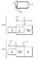
- Ballistically deployed restraining net system 10, Fig. 1, of this invention includes cartridge casing 12 having a base 14 and opposing open end 16, Fig. 4.
- Projectile 15 includes weight set 18, 20. 22, 24, 26, 28, 30, and 32 and eight other weights (not shown) attached to restraining net 34 within casing material 76.
- Projectile 15 is packaged within cartridge casing 12 with the weight set proximate the base portion of the cartridge casing.
- Deployment means such as a deployment charge in the form of 0.648 gram (ten grains) of gun powder 36, Fig. 4, eject restraining net 34 and weights 18-32 out of cartridge casing 12 which is fired from a 37 millimeter smooth bore tear gas gun.
- Spreader means or a spreader charge in the form of 0.334-0.648 gram (five to ten grains) of flash mix deploys weights 18-32 after they and net 34 exit the open end 16 of cartridge casing 12.
- one unique feature of the subject invention is that the set of weights 18-32 are packaged in back of instead of in front of the restraining net which surprisingly results in an increase of the range of the restraining net. Moreover, the safety of the restraining net system is increased because, should spreader charge 38 fail to fire, the net package will strike the target or perpetrator first rather than the weights as in previous designs.
- spreader charge 38 used to separate the weights when they are located in front of net 34, has a force F2 shown at 42 which acts against net 34 thereby decreasing its travel range.
- force F1 from spreader charge 38 as shown at 44, Fig. 3 urges net 34 forward and force F2 as shown at 42 also propels net 34 forward.
- the hammer of gun 50 strikes primer 52, Fig.4, of cartridge casing 12 which in turn ignites deployment charge 36 and delay fuse 54.
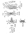
- the explosion of deployment charge 36 ejects the combination of weight and net package 56, Fig. 4, and approximately 20 to 30 milliseconds thereafter, as shown in Fig. 5B, delay fuse 54, Fig.4, ignites spreader charge 38 which spreads out weights 18-32 as shown in Fig. 5C.
- weights 18-32 are now fully deployed and as shown in Fig. 5E, net 34 is fully deployed as weights 18-32 accelerate ahead of net 34.
- Full deployment of net 34 occurs within about 1.524 m (5 feet) of gun 50, Fig. 5A.
- the effective capture zone for capturing perpetrator 60 is approximately 7.62 additional meters (25 additional feet) after full deployment at 1.524 m (5 feet). This increased range is an improvement over prior devices wherein the weights are always packaged in front of the capture net. And, as explained above, should spreader charge 38, Fig. 4 fail to fire, net 34 will strike perpetrator 60. Fig. 5E first rather than weight set 18-32.
- weights 18-32 are not attached directly to the perimeter 62, Fig. 5E of net 34 but instead are attached via .91 cm (3 foot) long leader lines 64 as shown for weight 18. These leader lines act in a "bola” like fashion to improve the effectiveness of the restraining net system. In the embodiment shown in Fig. 5E, the leader lines are attached to the perimeter 62 of 3.048 m (ten foot) diameter net 34.
- Weights 18-32, Fig. 4 are made of lead, rubber such as "Ultra High Mass” rubber available from the Griffiths Rubber Co. 2625 NW Industrial Portland, Oregon 97210, are fabricated of a lead core covered in rubber, or are made up of bean bag type structures.
- Each lead weight as shown for weight 18, has a hole through it as shown at 66 for attaching leader line 64 to the perimeter weight.
- the net is cut into an octagon shape and there are 16 weights, one attached to each corner of the octagon shaped net on 2.54 cm (one inch) leader lines and one disposed between the corners on 0.6096 m (two foot) leader lines.
- the short leader line weights function to deploy the net and the long leader line weights function to assist in the capture of the perpetrator via a bola type action.
- plastic plug 70 houses both deployment charge 36 and spreader charge 38.
- Plug 70 is receivable within cartridge 12 proximate base portion 14 thereof.
- Plug 70 includes cavity 72 for housing deployment charge 36.
- Spreader charge 38 is received on post 74 of plug 70 and there is an orifice through this post through which delay fuse 54 is received.
- the one piece design of plug 70 facilitates the efficiency of manufacturing the ballistically deploying net system of this invention.
- Net 34 is packaged within cardboard or heat shrinkable plastic housing 76 which may perforated as shown at 78 for assisting in its separation upon the ignition of spreader charge 38.
- housing 76 When packaged within cartridge 12, housing 76 is rendered nearly flush with the open end 16 of cartridge 12 as shown in Fig. 1.
- Orifice 80 created by the circle of weights 18-32 receives spreader charge 38. Weights 18-32 rest on surface 71 of plug 70.
- the perimeter weights 18. 20. 22. 24. 26. 28, and 30 are attached to net 34 such as they do not extend beyond the perimeter of the capture net.
- leader line 64a as shown for perimeter weight 18, is attached somewhere near the center of net 34 rather than at the perimeter as shown in phantom for close quarters or indoor maneuvers wherein the action of a perimeter weight striking surface 82 as shown at 84 would tend to collapse or tangle net 34.
- the "Ultra High Mass" rubber weights used in the preferred embodiment also reduce the chance that a given weight will bounce off surface 82.
- Net 32 may be fabricated from a lightweight, high strength twine or braided cord of nylon, Spectra or Kevlar. The Spectra and Kevlar materials have the advantage of high strength to weight, and low weight to volume ratios thus allowing a relatively large net with adequate line strength to be packaged into munitions for hand held launchers such as 37 mm and 40 mm caliber weapons.
- Cord breaking strengths on the order of 22.7 to 45.4 kg (50 to 100 lbs) are used for the personal capture nets.
- the net diameter and mesh size can be optimized for different munitions.
- Personal capture nets range in diameter from 3.04 m to 4.877 m (10 feet to 16 feet) with a mesh size ranging from 7.62 cm to 20.3 cm (3 inches to 8 inches).
- vectran netting available from FNT Industries, Inc., 927 First St., Menominee, MI 49858-0157 is used and cut into an within housing 76, Fig. 4, without the separate parts of the net sticking to each other.
- the nets are a knotted construction with a knot at each node or line intersection.
- the net knots are single knot square mesh netting knots, the perimeter line knots arc single overhand knots and the pull point knots are "double overhand" knots.
- the weights can be fabricated from any material which will provide the mass to fully deploy the net, provide forward momentum for sustained flight and enough momentum to swing the net around the target and become entangled.
- the net can be incorporated with one or more "sting" circuits to shock and disable a perpetrator.
- a power source 180 Fig. 7, such as a 6-volt battery, supplies current to sting circuits 182, 184, and 186 to provide open 50 kv electrical circuits integral within net 34, Fig. 5E.
- DC/DC voltage converter generator 181 with a step-up transformer and full wave bridge rectifier converts the battery voltage and charges energy storage capacitor 184 to an intermediate voltage of 500 to 1000V.
- Microcontroller 186 provides the ability to sequentially activate several electronic switches to channel the energy in storage capacitor 184 through a step-up transformer to wiring in the net.
- Several independent output circuits 182, 184, 186 each driven by one of the electric switches provide redundancy in case one or more of the circuits in the net is shorted or broken.
- Arming circuit 128 activates the sting circuit only after the net has been unfurled.
- Primary power is provided to first stage dc/dc converter 181 that produces an intermediate voltage of about 1000VDC and powers the individual sting circuits 182, 184, and 186. Power is also sent to the lethality level selector and controller 186.
- Circuit 186 controls the pulse rate and voltage level of the individual sting circuits.
- Capacitor 184 maintains energy storage in the intermediate voltage supply system.
- Sting circuits 182, 184, and 186 step the final voltage level up to 2kV to 100kV, depending on the level selected. Should one of the HVP outputs become shorted, the other circuits will continue to operate independently.
- non-tunable circuit 182a Fig. 8
- on/off switch 200 is automatically closed by arming circuit 128, Fig. 7 and power from battery 201 is applied to the circuit.
- Transistor 202, Fig. 8, together with transformer 206 form a self-oscillating DC-DC converter.
- the output of the converter is a transformer which produces a 400V AC signal across the diode 208.
- the output diode 208 is a half wave rectifier that converts the waveform back to a DC waveform of 200V peak.
- neon gas source 220 ionizes causing SCR 222 to turn on thereby discharging the voltage across transformer 226 which produces a 2000V charge at the output 230.
- Tunable sting circuit 182b produces extremely high voltages varying from 2kV to 100,000kV, at repetition rates between 1 and 20 pulses per second.
- the high voltage output pulse of circuit 182b is tunable prior to deployment to deliver different voltages to a perpetrator based on the circumstances.
- Circuit 182b provides a shock for 5 to 15 seconds, then turns off for 1 to 3 minutes before shocking again. This cycle will continue for up to 30 minutes or until the batteries die.
- a set of metal electrodes are incorporated into the net to apply the shock to the body.
- on/off switch 240 is automatically closed by arming circuit 128 to supply battery power to transistors 242 and 244 which, together with transformer 246, form a self-oscillating DC-DC converter.
- the output of the converter is a step-up transformer which produces a 2000V AC signal across the secondary winding of transformer 246.
- Diodes 248 and 250 form a full-wave rectifier that converts the waveform back to a DC waveform of 1000V.
- the transformer is sized to limit the current available at its output. The amount of energy available for each high voltage pulse is determined by the value of storage capacitance.
- Switch 252 permits capacitators 254 and 256 to be connected in parallel with capacitor 258 thereby increasing the duration of the output pulse.
- microcontroller 260 Periodically, microcontroller 260 triggers SCRs 262, 264 and 266, thereby completing a resonant circuit consisting of a capacitor 258 and the inductance of the primary winding of the step-up transformers 268, 270 and 272, etc.
- the output voltage is a decaying oscillation of peak magnitude of 2 to 100,000 kV with an oscillation frequency and pulse duration determined by the chosen position of switch 252. The user will have the option to disable the sting circuit prior to firing should the situation not warrant its use.
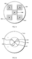
- the output from sting circuits 182, 184, and 186, Fig. 7, may be arranged as wires forming alternating concentric rings as shown in Fig. 10, as alternating pie slices as shown in Fig. 11, or as alternating lines as shown in Fig. 12.
- net 34, Fig. 13 may be used as a blockade in the form of an electric fence, with additional grounding wire 300.
- Another design includes 2.743 m (9 ft.) square circuits 302, 306, 308. 310, Fig. 14 and, each with four spirals spaced 10.16 cm (4 inches) apart.
- Still another design includes an 3.353 m (11 foot) diameter net 312.
- a capture film Fig. 5F
- films may be incorporated into a net for the purposes of aiding deployment, sustaining opened flight, and for the purpose of reducing the visibility of the target, thereby adding to confusion and enhancing entanglement and increasing escape times.
- the film is constructed of light weight, thin 0.0254 mm ( ⁇ .001 in.) polymer materials, optionally coated with reflective aluminum powder.
- the film is attached in layers on the leading edge in a series of concentric rings forming air passage which minimize aerodynamic drag.
- the films are also independent of the mesh therefore acting as a secondary barrier against escape. This independent construction where the film is on the outside prevents self entanglement of the law enforcement officer.
- markers foams, gaseous, liquid or power based markets, irritants or incapacitants can be incorporated into the net such as chloroacetophenone (CN), orthochlorobenzal-malononitrile (CS), oleoresin capsicum ,(OC), or their blends. Also a variety of UV or visual markers and dyes can be used.
- Sticky foam or other structural adhesives can be applied and in application, the net is encased in a polymer sock and sealed around the spreader gun. The net is stored in the adhesive. During deployment, the spreader gun ruptures the sock and spreads the net which is coated with the adhesive, irritant, or marker.
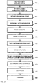
- Projectile 56, Fig. 4. is packaged in accordance with the methodology depicted via the flow chart shown in Fig. 21.
- the bulk net material is first cut into the desired shape, step 460.
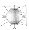
- the weights are then attached to the leader lines of the net as shown in Fig. 16.
- Eight weights, as shown for weight 26, are attached to each corner of the octagon shaped net via 2.54 cm (one inch) leader lines and eight additional weights are attached to each side of the net as shown for weight 28, step 462, Fig. 21.
- a 5.08 cm (two inch) wide nylon cloth perimeter strip 399, Fig. 16, is then woven around the perimeter of the net, step 464, Fig. 21.
- Perimeter strip 399 reduces the snapback effect of the net during deployment and also causes a flotation effect for net 34 during deployment.
- 1.219 m (48") long aluminum separator unit 400, Fig. 17, is then used, step 466, as follows.
- Each pair of weights, as shown for weights 26 and 28, Fig. 16, are held together and placed in a channel abutting bottom ring 402 of separator unit 400, Fig. 17.
- a piece of tape is then used to keep the weights in place about plug 404, Fig. 18.
- Separator unit 400, Fig. 17, is then hung vertically, step 470, Fig. 21.
- the tendrils of the net are then aligned and taped in the appropriate sectors of separator unit 400, step 472, Fig. 21.
- a piece of duct tape may then be placed about the weights and bottom ring 402 to keep it from sliding, step 468, Fig. 21.
- Tube 406 has a constant inner diameter of about 37mm.
- the sleeve is then heat shrunk about end 408 in all areas except the very top which will receive the weight set.
- Separator 400, Fig. 17, is then inserted into end 410 of acrylic tube 406, Fig. 19. While the acrylic tube is held steady, the net is drawn through acrylic tube 406 using a vacuum connected to end 412, step 474, Fig. 21.
- a plunger (not shown), is then inserted into end 412 of the acrylic tube and the net is compressed longitudinally until the net and weight package is fully within the heat shrinkable sleeve located about end 408 of acrylic tube 406.
- the assembly is ready for compression and compression jig 420, Fig. 20.
- the duct tape is removed and the plastic sleeve is slid over the weight set and a small round plug is placed between the weights to maintain the orientation, step 476, Fig. 21.
- the plastic sleeve is then removed from acrylic tube 406, Fig. 19, and the plastic sleeve now fully surrounds the net and the weights.
- Plastic spacer disk 426 Fig. 20, is placed in the acrylic tube abutting the net. Two opposing strips of duct tape are used to secure spacer disk 426 within the heat shrinkable plastic sleeve to keep it from wrinkling. This assembly is then placed in lower half 424 of jig 420 and end plug 428 is inserted so that it abuts the weights. The other half 422 of the compression jig is then coupled to lower half 424 and end plug cover 430 is secured to this assembly to maintain the position of end plug 428 during compression.
- Jig 420 is then placed in a press such as a Enerpack Press from Applied Power Industry and a pressure rod (not shown) is placed against spacer disk 426 and subjected to a pressure of about 0.5516 bar (8 psi) for five minutes, step 480, Fig. 21.
- a press such as a Enerpack Press from Applied Power Industry and a pressure rod (not shown) is placed against spacer disk 426 and subjected to a pressure of about 0.5516 bar (8 psi) for five minutes, step 480, Fig. 21.
- end cap 426 is removed, along with the duct tape securing it and a heat gun is used to heat shrink the ends of the plastic sleeve about the weight package.
- the spacer plug is then removed, a paper wafer is inserted in the plastic sleeve abutting the net, and the heat gun is then used to heat shrink the plastic sleeve about the paper wafer and the nets.
- Kapton disk is pressed in between the weights to protect them and their leader lines from heat caused by spreader charge 38, Fig. 4.
- the plastic sleeve is trimmed as necessary, and the projectile is now ready for insertion along with spreader charge 38 and plastic plug 70 into cartridge casing 12, Fig. 4, step 482, Fig. 21.
Landscapes
- Engineering & Computer Science (AREA)
- General Engineering & Computer Science (AREA)
- Radar, Positioning & Navigation (AREA)
- Remote Sensing (AREA)
- Chemical & Material Sciences (AREA)
- Combustion & Propulsion (AREA)
- Buffer Packaging (AREA)
- Catching Or Destruction (AREA)
- Packaging Of Annular Or Rod-Shaped Articles, Wearing Apparel, Cassettes, Or The Like (AREA)
- Burglar Alarm Systems (AREA)
- Addition Polymer Or Copolymer, Post-Treatments, Or Chemical Modifications (AREA)
- Pharmaceuticals Containing Other Organic And Inorganic Compounds (AREA)
- Devices Affording Protection Of Roads Or Walls For Sound Insulation (AREA)
Claims (16)
- Ein nicht-tödliches ballistisch ausgeworfenes bzw. ausgespreiztes Rückhaltenetz-System, das aus einem Handwerfer abgefeuert werden soll, wobei besagtes System aufweist:eine Patrone, die in einem Lauf aufgenommen werden kann, wobei besagte Patrone aufweist: Eine Patronenhülse (12) mit einem Boden (14) und einem gegenüberliegenden offenen Ende (16),dadurch gekennzeichnet, daß besagtes Netz-System weiter einen Stopfen (70) aufweist, der innerhalb der Patronenhülse (12) zunächst besagtem Boden (14) aufgenommen werden kann, wobei besagter Stopfen (70) aufweist eine erste Oberfläche, eine zweite Oberfläche gegenüberliegend besagter erster Oberfläche, eine Höhlung (72) in besagter erster Oberfläche besagten Stopfens (70) um besagte Auswerfladung (36) aufzunehmen, wobei besagte Spreizladung auf besagter zweiter Oberfläche besagten Stopfens (70) plaziert ist, eine Öffnung durch besagten Stopfen in Verbindung mit beiden Oberflächen, in der sich besagte Verzögerungszündung (54)befindet, wobei besagte Verzögerungszündung (54) an einem ihrer Enden mit besagter Spreizladung (38) und an deren anderem Ende mit besagter Auswerfladung (36) in Verbindung ist, und dadurch, daß-- ein nicht-tödliches Rückhaltenetz (34) oder Rückhaltefolie, die in der Patronenhülse nächst dem offenem Ende eingepackt ist,-- einen Satz von Gewichten (18, 20, 22, 24, 26, 28, 30 und 32), angebracht an besagtem Rückhaltenetz (34) und eingepackt innerhalb der Patronenhülse (12) zwischen dem Boden (14) der Patronehülse und dem Rückhaltenetz (34),-- eine Auswerfladung (36), die sich zwischen dem Boden der Patronenhülse (12) und dem Gewichtssatz befindet um besagtes Rückhaltenetz (34) und besagten Gewichtssatz aus dem Lauf und aus besagter Patronenhülse (12) auszustoßen,-- eine Zündung (52) in Nachrichtenverbindung mit besagter Auswerfladung (36),-- eine Spreizladung (38), die sich zwischen besagter Auswerfladung und besagtem Gewichtssatz befindet und zunächst besagten Gewichten in Stellung gebracht ist um besagte Gewichte zu verteilen, nachdem besagtes Netz (34) und besagter Gewichtssatz aus der Patronenhülse (12) austreten, worin die Gewichte am Umfang angeordnet sind und die Spreizladung benachbart oder innerhalb der Umfangsanordnung der Gewichte plaziert ist, und-- eine Verzögerungssicherung oder -zündschnur, die zwischen besagter Auswerfladung und besagter Spreizladung in Stellung gebracht ist, in Nachrichtenverbindung mit besagter Auswerfladung und besagter Spreizladung um besagte Spreizladung auszulösen nach einer Zeitverzögerung zur Auslösung der Auswerfladung,
das Rückhaltenetz (34), der Gewichtssatz (18-32), die Auswerfladung (36), die Spreizladung (38), die Verzögerungszündung (54) und der Stopfen (70) innerhalb der Patronenhülse (12) eingepackt sind. - Das System des Anspruchs 1, in dem besagte Gewichte an besagtem Rückhaltenetz (34) über Führungsschnüre (64) angebracht sind.
- Das System des Anspruchs 2, in dem besagte Führungsschnüre (64) an dem Umfang (62) besagten Rückhaltenetzes (34) angebracht sind.
- Das System des Anspruchs 2, in dem besagtes Führungsschnüre (64) an inneren Abschnitten besagten Rückhaltenetzes (34) angebracht sind.
- Das System des Anspruchs 1, weiter aufweisend ein Gehäuse (76) für besagtes Rückhaltenetz (34).
- Das System des Anspruchs 5, in dem besagtes Gehäuse (76) Lochungen (78) aufweist, um das Auswerfen besagten Rückhaltenetzes (34) zu erleichtern.
- Das System des Anspruchs 1, in dem besagte Gewichte (18, 20, 22, 24, 26, 28, 30 und 32) Gummi sind.
- Das System des Anspruchs 1, in dem besagte Gewichte (18, 20, 22, 24, 26, 28, 30 und 32) Blei sind.
- Das System des Anspruchs 1, in dem besagte Gewichte (18, 20, 22, 24, 26, 28, 30 und 32) metallisch, umgeben von einem Gummiäußeren, sind.
- Das System des Anspruchs 1, in dem besagtes Netz eine Kraftquelle (180) und eine offene elektrische Schaltung, die an besagte Kraftquelle angeschlossen ist, um ein Ziel, das in besagtem Netz gefangen ist, auszuschalten, aufweist.
- Ein Verfahren des ballistischen Ausspreizens eines nicht-tödlichen Rückhaltenetz-Systems, wobei das Verfahren aufweist:Einpacken ein nicht-tödliches Rückhaltenetz (34) und einen Gewichtssatz (18, 20, 22, 24, 26, 28, 30 und 32), der an dem Rückhaltenetz (34) angebracht ist innerhalb einer Patronehülse (12) zum Abfeuern von einem Handwerfer derart, daß sich die Gewichte zwischen dem Boden (14) der Patronenhülse (12) und dem Rückhaltenetz (34) befinden und das Rückhaltenetz sich zunächst einem offenen Ende der Patronenhülse (12) befindet, eine Auswerfladung (36), die einen Zünder (32) in Verbindung mit besagter Auswerfladung (36) aufweist, zwischen dem Boden der Patronenhülse (12) und dem Gewichtssatz, eine Spreizladung (38), die sich zwischen besagter Auswerfladung und besagtem Gewichtssatz befindet und nächst besagten Gewichten in Stellung gebracht ist um besagte Gewichte auszuspreizen nachdem besagtes Netz (34) und besagter Gewichtssatz aus der Patronenhülse (12) austreten, worin die Gewichte am Umfang angeordnet sind und die Spreizladung benachbart oder innerhalb der Umfangsanordnung der Gewichte platziert ist, und einen Stopfen (70), der innerhalb der Patronenhülse (12) zunächst besagtem Boden (14) aufgenommen werden kann, wobei besagter Stopfen (70) aufweist eine erste Oberfläche, eine zweite Oberfläche gegenüber besagter erster Oberfläche, eine Höhlung (72) in besagter erster Oberfläche besagten Stopfens um besagte Auswerfladung aufzunehmen, wobei besagte Spreizladung auf besagter zweiter Oberfläche besagten Stopfens (70) plaziert ist, eine Öffnung durch besagten Stopfen in Verbindung mit beiden Oberflächen, in der sich besagte Verzögerungszündung (54) befindet, wobei besagte Verzögerungszündung (54) an einem ihrer Enden mit besagter Spreizladung (38) und an deren anderem Ende mit besagter Auswerfladung (36) in Verbindung ist,Ausstoßen besagten Rückhaltenetzes (34) und besagten Gewichtsatzes aus einem Lauf und aus besagter Patronenhülse (12), undAuslösen der Spreizladung (38) durch eine Verzögerungszündung, die zwischen besagter Auswerfladung und besagter Spreizladung in Stellung gebracht ist, in Nachrichtenverbindung mit besagter Auswerfladung und besagter Spreizladung um besagte Gewichte auszuspreizen nachdem besagtes Netz (34) und besagter Gewichtssatz aus dem Patronengehäuse (12) austreten, worin die Gewichte umfangsmäßig angeordnet sind und die Spreizladung (38) benachbart oder innerhalb der umfangsmäßigen Anordnung der Gewichte plaziert ist.
- Das Verfahren des Anspruchs 11, in dem besagte Gewichte an besagtem Rückhaltenetz (34) über Führungsschnüre (64) angebracht sind.
- Das Verfahren des Anspruchs 12, in dem besagte Führungsschnüre (64) am Umfang (62) besagten Rückhaltenetzes (34) angebracht sind.
- Das Verfahren des Anspruchs 12, in dem besagte Führungsschnüre (64) an einem inneren Abschnitt besagten Rückhaltenetzes (34) angebracht sind.
- Das Verfahren des Anspruchs 11, weiter aufweisend das Plazieren eines Gehäuses (76) um besagtes Rückhaltenetz (34), das innerhalb der Patronenhülse (12) aufgenommen werden kann.
- Das Verfahrendes des Anspruchs 15, weiter aufweisend das Durchlöchern des Gehäuses (76) um das Ausspreizen besagten Rückhaltenetzes (34) zu erleichtern.
Applications Claiming Priority (3)
| Application Number | Priority Date | Filing Date | Title |
|---|---|---|---|
| US08/866,745 US5898125A (en) | 1995-10-17 | 1997-05-30 | Ballistically deployed restraining net |
| PCT/US1998/009855 WO1998054538A1 (en) | 1997-05-30 | 1998-05-14 | Ballistically deployed restraining net system |
| US866745 | 2004-06-15 |
Publications (3)
| Publication Number | Publication Date |
|---|---|
| EP0983480A2 EP0983480A2 (de) | 2000-03-08 |
| EP0983480A4 EP0983480A4 (de) | 2000-11-08 |
| EP0983480B1 true EP0983480B1 (de) | 2007-03-07 |
Family
ID=25348317
Family Applications (1)
| Application Number | Title | Priority Date | Filing Date |
|---|---|---|---|
| EP98922288A Expired - Lifetime EP0983480B1 (de) | 1997-05-30 | 1998-05-14 | Ballistisch ausspreizbares rückhaltenetz |
Country Status (7)
| Country | Link |
|---|---|
| US (2) | US5898125A (de) |
| EP (1) | EP0983480B1 (de) |
| JP (1) | JP3449732B2 (de) |
| AT (1) | ATE356334T1 (de) |
| CA (1) | CA2291809C (de) |
| DE (1) | DE69837256T2 (de) |
| WO (1) | WO1998054538A1 (de) |
Cited By (1)
| Publication number | Priority date | Publication date | Assignee | Title |
|---|---|---|---|---|
| WO2012082012A3 (ru) * | 2010-12-14 | 2012-09-13 | В & С Ворлд Ко. Лтд | Снаряд дистанционного электрошокового оружия и способ его изготовления |
Families Citing this family (113)
| Publication number | Priority date | Publication date | Assignee | Title |
|---|---|---|---|---|
| US5898125A (en) * | 1995-10-17 | 1999-04-27 | Foster-Miller, Inc. | Ballistically deployed restraining net |
| DE19832777B4 (de) * | 1998-07-22 | 2008-08-28 | J.P. Sauer & Sohn GmbH gegründet 1751 | Feuerwaffe, insbesondere Selbstladepistole |
| AU5489700A (en) * | 1999-06-18 | 2001-01-09 | Less Lethal, Inc. | Bean bag baton |
| US7075770B1 (en) * | 1999-09-17 | 2006-07-11 | Taser International, Inc. | Less lethal weapons and methods for halting locomotion |
| US6820560B1 (en) | 1999-09-30 | 2004-11-23 | Juha Romppanen | Non-killing cartridge |
| US6202562B1 (en) | 1999-11-05 | 2001-03-20 | Michael Brunn | Method of preparing a low lethality projectile for flight |
| US6374742B1 (en) | 1999-11-05 | 2002-04-23 | Michael Brunn | Method of preparing a low lethality projectile for flight in 37mm and 40mm weapon shells |
| WO2001060689A1 (en) | 2000-02-18 | 2001-08-23 | General Dynamics Ordnance And Tactical Systems, Inc. | Deployable net for control of watercraft |
| US6381894B1 (en) | 2000-08-29 | 2002-05-07 | The United States Of America As Represented By The Secretary Of The Navy | Bola launcher |
| DE60113372T2 (de) * | 2001-02-20 | 2006-06-22 | Raikka Oy | Nichttödliche Patrone |
| US6782828B2 (en) * | 2001-04-09 | 2004-08-31 | Charles D. Widener | Pliant firearm projectiles |
| US6997110B2 (en) * | 2001-09-05 | 2006-02-14 | Omnitek Partners, Llc. | Deployable bullets |
| US6655294B1 (en) * | 2002-01-21 | 2003-12-02 | James T. Kerr | Ammunition for a less-lethal projectile |
| US6763875B2 (en) | 2002-02-06 | 2004-07-20 | Andersen Corporation | Reduced visibility insect screen |
| GB0206676D0 (en) * | 2002-03-21 | 2002-10-30 | Roke Manor Research | Target immobilisation device |
| CN2544359Y (zh) * | 2002-06-07 | 2003-04-09 | 宋有洲 | 室内防暴捕捉器 |
| US6880466B2 (en) * | 2002-06-25 | 2005-04-19 | Brent G. Carman | Sub-lethal, wireless projectile and accessories |
| US7145762B2 (en) * | 2003-02-11 | 2006-12-05 | Taser International, Inc. | Systems and methods for immobilizing using plural energy stores |
| US6776079B1 (en) | 2003-07-25 | 2004-08-17 | The United States Of America As Represented By The Secretary Of The Navy | Asymetrically contoured elastomeric disk |
| US7057872B2 (en) | 2003-10-07 | 2006-06-06 | Taser International, Inc. | Systems and methods for immobilization using selected electrodes |
| US7042696B2 (en) | 2003-10-07 | 2006-05-09 | Taser International, Inc. | Systems and methods using an electrified projectile |
| US7602597B2 (en) * | 2003-10-07 | 2009-10-13 | Taser International, Inc. | Systems and methods for immobilization using charge delivery |
| DE602004032268D1 (de) * | 2003-10-07 | 2011-05-26 | Taser Int Inc | Systeme zur bewegungshemmung |
| CN100511902C (zh) * | 2003-10-07 | 2009-07-08 | 天射国际公司 | 利用所选电极制动的系统和方法 |
| US7701692B2 (en) * | 2003-11-13 | 2010-04-20 | Taser International, Inc. | Systems and methods for projectile status reporting |
| US7398617B2 (en) * | 2004-01-30 | 2008-07-15 | Harry Mattox | Method and apparatus for deploying an animal restraining net |
| US6904838B1 (en) * | 2004-03-30 | 2005-06-14 | The United States Of America As Represented By The Secretary Of The Army | Ballistically deployed restraining net |
| US7278357B2 (en) * | 2004-04-08 | 2007-10-09 | Keith Michael A | Accuracy less lethal projectile |
| US7387387B2 (en) * | 2004-06-17 | 2008-06-17 | Amo Manufacturing Usa, Llc | Correction of presbyopia using adaptive optics and associated methods |
| US7520081B2 (en) * | 2004-07-13 | 2009-04-21 | Taser International, Inc. | Electric immobilization weapon |
| US20060169832A1 (en) * | 2005-01-06 | 2006-08-03 | Glasson Richard O | Rocket propelled barrier defense system |
| US8399816B2 (en) * | 2005-01-06 | 2013-03-19 | Cpi Ip, Llc | Rocket propelled barrier defense system |
| US7314007B2 (en) * | 2005-02-18 | 2008-01-01 | Li Su | Apparatus and method for electrical immobilization weapon |
| JP4975436B2 (ja) * | 2005-10-17 | 2012-07-11 | 日本工機株式会社 | 携行型拘束網展開装置 |
| US20090217811A1 (en) | 2006-01-17 | 2009-09-03 | David William Leeming | Textile armour |
| US7866250B2 (en) | 2006-02-09 | 2011-01-11 | Foster-Miller, Inc. | Vehicle protection system |
| US7900548B2 (en) | 2006-02-09 | 2011-03-08 | Foster Miller, Inc. | Protection system including a net |
| US7986506B2 (en) * | 2006-05-03 | 2011-07-26 | Taser International, Inc. | Systems and methods for arc energy regulation and pulse delivery |
| US20070261542A1 (en) * | 2006-05-09 | 2007-11-15 | Chang Industry, Inc. | Airborne platform protection apparatus and associated system and method |
| US7305981B1 (en) * | 2006-06-13 | 2007-12-11 | Hsin-Hung Lin | Anti-riot device |
| JP2009544000A (ja) * | 2006-07-17 | 2009-12-10 | エヴゲニエヴィッチ ナズドラチェンコ、アンドレイ | 網投射装置 |
| US7582988B2 (en) | 2006-09-30 | 2009-09-01 | Zareba Security, Inc. | Lethal electric fence energizer |
| US7786417B2 (en) * | 2006-12-11 | 2010-08-31 | Dese Research, Inc. | RAM neutralization system and method |
| EP2205929B1 (de) * | 2007-03-29 | 2015-10-07 | Mechanical Solutions Inc. | System zum schutz vor raketen |
| US7984676B1 (en) | 2007-06-29 | 2011-07-26 | Taser International, Inc. | Systems and methods for a rear anchored projectile |
| US7856929B2 (en) | 2007-06-29 | 2010-12-28 | Taser International, Inc. | Systems and methods for deploying an electrode using torsion |
| US20090174555A1 (en) * | 2008-01-06 | 2009-07-09 | Lin Yung-San | Mesh-type anti-theft device |
| US8245620B2 (en) * | 2008-04-16 | 2012-08-21 | QinetiQ North America, Inc. | Low breaking strength vehicle and structure shield net/frame arrangement |
| US8468927B2 (en) | 2008-04-16 | 2013-06-25 | QinetiQ North America, Inc. | Vehicle and structure shield with a cable frame |
| US8615851B2 (en) | 2008-04-16 | 2013-12-31 | Foster-Miller, Inc. | Net patching devices |
| US8443709B2 (en) * | 2008-04-16 | 2013-05-21 | QinetiQ North America, Inc. | Vehicle and structure shield hard point |
| US8464627B2 (en) | 2008-04-16 | 2013-06-18 | QinetiQ North America, Inc. | Vehicle and structure shield with improved hard points |
| US20110079135A1 (en) | 2008-04-16 | 2011-04-07 | Farinella Michael D | Vehicle and structure shield net/frame arrangement |
| US8607685B2 (en) | 2008-04-16 | 2013-12-17 | QinetiQ North America, Inc. | Load sharing hard point net |
| US8453552B2 (en) | 2008-04-16 | 2013-06-04 | QinetiQ North America, Inc. | Method of designing an RPG shield |
| US8011285B2 (en) | 2008-04-16 | 2011-09-06 | Foster-Miller, Inc. | Vehicle and structure shield |
| US8024889B2 (en) | 2008-06-25 | 2011-09-27 | Brett Bunker | Pest control method and apparatus |
| US8205537B1 (en) * | 2008-08-11 | 2012-06-26 | Raytheon Company | Interceptor projectile with net and tether |
| US8387540B2 (en) * | 2008-08-11 | 2013-03-05 | Raytheon Company | Interceptor projectile and method of use |
| US8375837B2 (en) * | 2009-01-19 | 2013-02-19 | Honeywell International Inc. | Catch and snare system for an unmanned aerial vehicle |
| US7964830B2 (en) * | 2009-02-23 | 2011-06-21 | Raytheon Company | Large cross-section interceptor vehicle and method |
| EP2567177A2 (de) | 2010-05-06 | 2013-03-13 | Warwick Mills, Inc. | System zur linderung der bedrohung durch von selbstmordattentätern herbbeigeführte explosionen |
| US8677882B2 (en) | 2010-09-08 | 2014-03-25 | QinetiQ North America, Inc. | Vehicle and structure shield with flexible frame |
| EP2453199B1 (de) | 2010-11-16 | 2014-06-04 | Mechanical Solutions Inc. | System zum Schutz gegen Projektile |
| WO2012078215A1 (en) * | 2010-12-06 | 2012-06-14 | Raytheon Company | Non-lethal delivery canister, threat mitigation system, and methods for mitigating bomber and perpetrator threats |
| US8596178B2 (en) | 2011-01-28 | 2013-12-03 | The Boeing Company | Expanding countermeasure and launcher system |
| US9074858B2 (en) * | 2012-07-13 | 2015-07-07 | The Boeing Company | Projectile-deployed countermeasure system |
| US9091513B2 (en) * | 2012-09-06 | 2015-07-28 | Jason J. Shand | Method and apparatus for guided missile and/or net shield |
| US8813631B1 (en) | 2013-02-13 | 2014-08-26 | Foster-Miller, Inc. | Vehicle and structure film/hard point shield |
| US9134099B2 (en) * | 2013-12-16 | 2015-09-15 | Starjet Technologies Co., Ltd. | Net throwing device |
| JP6517025B2 (ja) * | 2015-01-27 | 2019-05-22 | 日本工機株式会社 | 携行型拘束網展開装置 |
| US20170356726A1 (en) | 2015-02-26 | 2017-12-14 | Shawn M. Theiss | Aerial arresting system for unmanned aerial vehicle |
| DE102015003324A1 (de) * | 2015-03-17 | 2016-09-22 | Diehl Bgt Defence Gmbh & Co. Kg | Projektil zum Abfangen einer Kleindrohne |
| US10663266B2 (en) * | 2015-08-27 | 2020-05-26 | Airspace Systems, Inc. | Interdiction system and method of operation |
| WO2017083361A1 (en) * | 2015-11-10 | 2017-05-18 | Leimbach Wendell B | Portable net and deployment system |
| WO2017160750A1 (en) * | 2016-03-12 | 2017-09-21 | Kestrel Science and Innovation, LLC | Interdiction and recovery for small unmanned aircraft systems |
| US10107599B2 (en) * | 2016-03-25 | 2018-10-23 | Wrap Technologies, Inc. | Entangling projectiles and systems for their use |
| US10036615B2 (en) * | 2016-03-25 | 2018-07-31 | Wrap Technologies, Inc. | Entangling projectile deployment system |
| US9989336B2 (en) | 2017-02-17 | 2018-06-05 | James W. Purvis | Device for non-lethal immobilization of threats |
| US10634461B2 (en) | 2017-06-24 | 2020-04-28 | Wrap Technologies, Inc. | Entangling projectiles and systems for their use |
| USD822785S1 (en) | 2017-09-29 | 2018-07-10 | Wrap Technologies, Inc. | Projectile casing |
| USD820940S1 (en) | 2017-09-29 | 2018-06-19 | Wrap Technologies, Inc. | Projectile launcher |
| US11027845B2 (en) | 2017-09-29 | 2021-06-08 | Shawn M. Theiss | Device and method to intercept an aerial vehicle |
| WO2019079288A1 (en) | 2017-10-18 | 2019-04-25 | Wrap Technologies, Inc. | SYSTEMS AND METHODS FOR GENERATING TARGETING BEAMS |
| US10852114B2 (en) | 2018-07-03 | 2020-12-01 | Wrap Technologies, Inc. | Adhesive-carrying entangling projectiles and systems for their use |
| US11371810B2 (en) | 2018-07-03 | 2022-06-28 | Wrap Technologies, Inc. | Seal-carrying entangling projectiles and systems for their use |
| US10866069B1 (en) * | 2018-09-07 | 2020-12-15 | Counter Assault Security Services, Llc | Device for nonlethally incapacitating a human target |
| US11835320B2 (en) | 2018-09-11 | 2023-12-05 | Wrap Technologies, Inc. | Systems and methods for non-lethal, near-range detainment of subjects |
| US10890419B2 (en) | 2018-09-11 | 2021-01-12 | Wrap Technologies, Inc. | Systems and methods for non-lethal, near-range detainment of subjects |
| US10859346B2 (en) * | 2018-10-31 | 2020-12-08 | Fortem Technologies, Inc. | System and method of managing a projectile module on a flying device |
| US11498679B2 (en) | 2018-10-31 | 2022-11-15 | Fortem Technologies, Inc. | System and method of providing a projectile module having a net with a drawstring |
| US11597517B2 (en) * | 2018-10-31 | 2023-03-07 | Fortem Technologies, Inc. | System and method of providing a cocklebur net in a projectile module |
| US12209844B2 (en) | 2018-10-31 | 2025-01-28 | Fortem Technologies, Inc. | System and method of managing a plurality of projectile modules on a flying device |
| US10948269B2 (en) | 2018-12-04 | 2021-03-16 | Wrap Technologies Inc. | Perimeter security system with non-lethal detainment response |
| ES2799373A1 (es) * | 2019-06-13 | 2020-12-16 | Ruiz Juan Antonio Zamora | Cartucho con red para escopeta |
| US11280591B2 (en) * | 2019-09-03 | 2022-03-22 | Harkind Dynamics, LLC | Intelligent munition |
| US11493310B1 (en) | 2019-09-09 | 2022-11-08 | Counter Assault Security Services, Llc | Net for nonlethally incapacitating a target |
| JP7364416B2 (ja) * | 2019-10-15 | 2023-10-18 | 日本工機株式会社 | 捕獲網展開飛翔装置 |
| GB202001705D0 (en) * | 2020-02-07 | 2020-03-25 | Synbiosys Ltd | A vehicle arrest device |
| US11156432B1 (en) | 2020-08-31 | 2021-10-26 | Wrap Techologies, Inc. | Protective coverings and related methods for entangling projectiles |
| JP7437764B2 (ja) | 2020-09-14 | 2024-02-26 | 株式会社オン | 捕獲装置 |
| US11674778B1 (en) | 2020-10-14 | 2023-06-13 | Clifford L. Borter | Projectile entangling device, cartridge and method |
| US11761737B2 (en) | 2021-02-18 | 2023-09-19 | Wrap Technologies, Inc. | Projectile launching systems with anchors having dissimilar flight characteristics |
| US11555673B2 (en) | 2021-02-18 | 2023-01-17 | Wrap Technologies, Inc. | Projectile launching systems with anchors having dissimilar flight characteristics |
| GB2611336B (en) * | 2021-09-30 | 2024-06-05 | Gibson Robotics Ltd | Net-launching system |
| US11852439B2 (en) | 2021-11-24 | 2023-12-26 | Wrap Technologies, Inc. | Systems and methods for generating optical beam arrays |
| DE102023000394A1 (de) | 2023-02-08 | 2024-08-08 | Stanislav Tkadlec | Sonder-Gefechtskopf |
| KR102575841B1 (ko) * | 2023-03-21 | 2023-09-06 | 최진호 | 불법 드론 포획용 포획탄 |
| US12264899B2 (en) | 2023-04-04 | 2025-04-01 | Wrap Technologies, Inc. | Anchors for entangling projectiles |
| KR102705825B1 (ko) * | 2023-06-30 | 2024-09-12 | 송민규 | 드론 포획탄 |
| US20250290733A1 (en) * | 2024-02-05 | 2025-09-18 | Nl Enterprises, Llc | Projectile Construction and Payloads Therefor |
| WO2025178516A1 (ru) * | 2024-06-07 | 2025-08-28 | Андрей Валерьевич РИЯНОВ | Приспособление для присоединения к боеприпасу дополнительного поражающего элемента |
| US12584716B1 (en) | 2024-11-25 | 2026-03-24 | Dorian Cucereanu | Aerial drone incapacitator |
Family Cites Families (28)
| Publication number | Priority date | Publication date | Assignee | Title |
|---|---|---|---|---|
| US1309530A (en) * | 1919-07-08 | Aircraft-projectile | ||
| US644896A (en) * | 1898-05-09 | 1900-03-06 | John J Coneys | Explosive shell. |
| US1388503A (en) * | 1919-02-04 | 1921-08-23 | Newton D Baker | Canister |
| US2251918A (en) * | 1939-03-15 | 1941-08-12 | Horace W Dawson | Antiaircraft projectile |
| US2373363A (en) * | 1939-04-05 | 1945-04-10 | Wellcome Hubert | Projectile |
| FR859282A (fr) * | 1939-05-04 | 1940-12-14 | Projectile à filet | |
| US2776621A (en) * | 1954-06-28 | 1957-01-08 | Rosenblatt Jordan | Projectile |
| US2866412A (en) * | 1956-03-14 | 1958-12-30 | Arthur R Meyer | Cylindrical obturating cartridge |
| US3400660A (en) * | 1965-10-20 | 1968-09-10 | Richard L. Malter | Ammunition projectile |
| US3710720A (en) * | 1970-05-21 | 1973-01-16 | Mb Ass | High energy minimum lethality weapon system |
| US4014263A (en) * | 1976-02-23 | 1977-03-29 | The United States Of America As Represented By The Secretary Of The Army | Caseless projectile |
| US4253132A (en) * | 1977-12-29 | 1981-02-24 | Cover John H | Power supply for weapon for immobilization and capture |
| DE2844675A1 (de) * | 1978-10-13 | 1980-04-24 | Heckler & Koch Gmbh | Nichttoedliches wuchtgeschoss |
| GB2166225A (en) * | 1984-10-27 | 1986-04-30 | Leslie Charles Hall | Riot control |
| DE3522661A1 (de) * | 1985-06-25 | 1987-01-08 | Gerhard Norbutat | Verfahren, mittels klebebaendern angriffe abzuwehren |
| US4768417A (en) * | 1987-10-13 | 1988-09-06 | Wright James E | Detonator net weapon |
| US4912869A (en) * | 1987-11-02 | 1990-04-03 | Tetra Industries Pty. Limited | Net gun |
| US5649466A (en) * | 1992-11-25 | 1997-07-22 | The United States Of America As Represented By The Secretary Of The Army | Method of rapidly deploying volume-displacement devices for restraining movement of objects |
| DE9402227U1 (de) * | 1993-04-23 | 1994-09-15 | Bugiel, Horst-Georg, Dipl.-Ing., 53127 Bonn | Selbstschutz-Einrichtung |
| US5326101A (en) * | 1993-05-03 | 1994-07-05 | Fay Larry R | Law enforcement baton with projectable restraining net |
| CH688946A5 (fr) * | 1993-11-01 | 1998-06-15 | Frederic Baillod | Dispositif de capture, notamment pour arme à feu. |
| DE4409424C1 (de) * | 1994-03-18 | 1995-08-10 | Daimler Benz Aerospace Ag | Abfangvorrichtung für Flugobjekte |
| DE4439762C1 (de) * | 1994-11-07 | 1995-12-07 | Daimler Benz Aerospace Ag | Personen-Fernfessel |
| JP3223756B2 (ja) * | 1995-05-23 | 2001-10-29 | ヤマハ株式会社 | ミュージックシステムおよび電子楽器 |
| US5750918A (en) * | 1995-10-17 | 1998-05-12 | Foster-Miller, Inc. | Ballistically deployed restraining net |
| US5898125A (en) * | 1995-10-17 | 1999-04-27 | Foster-Miller, Inc. | Ballistically deployed restraining net |
| US5698815A (en) * | 1995-12-15 | 1997-12-16 | Ragner; Gary Dean | Stun bullets |
| JP5542319B2 (ja) | 2008-11-10 | 2014-07-09 | 株式会社日立産機システム | 電気チェーンブロック |
-
1997
- 1997-05-30 US US08/866,745 patent/US5898125A/en not_active Expired - Lifetime
-
1998
- 1998-05-14 EP EP98922288A patent/EP0983480B1/de not_active Expired - Lifetime
- 1998-05-14 DE DE69837256T patent/DE69837256T2/de not_active Expired - Fee Related
- 1998-05-14 JP JP50072099A patent/JP3449732B2/ja not_active Expired - Fee Related
- 1998-05-14 CA CA002291809A patent/CA2291809C/en not_active Expired - Fee Related
- 1998-05-14 WO PCT/US1998/009855 patent/WO1998054538A1/en not_active Ceased
- 1998-05-14 AT AT98922288T patent/ATE356334T1/de not_active IP Right Cessation
-
1999
- 1999-01-13 US US09/229,696 patent/US5988036A/en not_active Expired - Lifetime
Cited By (2)
| Publication number | Priority date | Publication date | Assignee | Title |
|---|---|---|---|---|
| WO2012082012A3 (ru) * | 2010-12-14 | 2012-09-13 | В & С Ворлд Ко. Лтд | Снаряд дистанционного электрошокового оружия и способ его изготовления |
| RU2486451C2 (ru) * | 2010-12-14 | 2013-06-27 | В & C Ворлд Ко. Лтд | Снаряд дистанционного электрошокового оружия и способ его изготовления |
Also Published As
| Publication number | Publication date |
|---|---|
| JP3449732B2 (ja) | 2003-09-22 |
| CA2291809A1 (en) | 1998-12-03 |
| HK1028994A1 (en) | 2001-03-16 |
| WO1998054538A1 (en) | 1998-12-03 |
| EP0983480A4 (de) | 2000-11-08 |
| EP0983480A2 (de) | 2000-03-08 |
| DE69837256D1 (de) | 2007-04-19 |
| US5988036A (en) | 1999-11-23 |
| ATE356334T1 (de) | 2007-03-15 |
| US5898125A (en) | 1999-04-27 |
| JP2000513089A (ja) | 2000-10-03 |
| DE69837256T2 (de) | 2007-12-20 |
| CA2291809C (en) | 2002-08-20 |
Similar Documents
| Publication | Publication Date | Title |
|---|---|---|
| US5898125A (en) | Ballistically deployed restraining net | |
| US5750918A (en) | Ballistically deployed restraining net | |
| US5831199A (en) | Weapon for immobilization and capture | |
| US7096792B1 (en) | Sub-lethal, wireless projectile and accessories | |
| US7859818B2 (en) | Electronic control device with wireless projectiles | |
| US5962806A (en) | Non-lethal projectile for delivering an electric shock to a living target | |
| US6802261B2 (en) | Tetherless neuromuscular disrupter gun with liquid-based capacitor (spray discharge) | |
| US6381894B1 (en) | Bola launcher | |
| US20070019358A1 (en) | Immobilization weapon | |
| CA2162221A1 (en) | Long-range personal restraining device | |
| KR20080039900A (ko) | 신경근육 파괴에 의해 타깃을 이동 불가능하게 하기 위한비살상 무선 스턴 발사체 시스템 | |
| WO2007001987A2 (en) | High efficiency power supply circuit for an electrical discharge weapon | |
| EP1893934A2 (de) | Geschoss für eine elektroschockwaffe | |
| WO1998054538B1 (en) | Ballistically deployed restraining net system | |
| US12044509B1 (en) | Projectile entangling device, cartridge and method | |
| US6845715B2 (en) | Explosion simulator | |
| HK1028994B (en) | Ballistically deployed restraining net system | |
| RU2790259C1 (ru) | Способ нелетального воздействия на биологическую цель и устройство для его осуществления | |
| RU2439480C2 (ru) | Боеприпас нелетального действия | |
| JPH11337296A (ja) | 不動化及び捕獲のための改良された武器 | |
| FR3105392A1 (fr) | Pistolet à impulsion électrique à mécanisme de propulsion magnétique des dards. | |
| IL148109A (en) | Explosion simulator |
Legal Events
| Date | Code | Title | Description |
|---|---|---|---|
| PUAI | Public reference made under article 153(3) epc to a published international application that has entered the european phase |
Free format text: ORIGINAL CODE: 0009012 |
|
| 17P | Request for examination filed |
Effective date: 19991129 |
|
| AK | Designated contracting states |
Kind code of ref document: A2 Designated state(s): AT BE CH CY DE DK ES FI FR GB GR IE IT LI LU MC NL PT SE |
|
| A4 | Supplementary search report drawn up and despatched |
Effective date: 20000921 |
|
| AK | Designated contracting states |
Kind code of ref document: A4 Designated state(s): AT BE CH CY DE DK ES FI FR GB GR IE IT LI LU MC NL PT SE |
|
| RIC1 | Information provided on ipc code assigned before grant |
Free format text: 7F 42B 12/00 A, 7F 42B 12/66 B |
|
| 17Q | First examination report despatched |
Effective date: 20030204 |
|
| GRAP | Despatch of communication of intention to grant a patent |
Free format text: ORIGINAL CODE: EPIDOSNIGR1 |
|
| GRAS | Grant fee paid |
Free format text: ORIGINAL CODE: EPIDOSNIGR3 |
|
| GRAA | (expected) grant |
Free format text: ORIGINAL CODE: 0009210 |
|
| AK | Designated contracting states |
Kind code of ref document: B1 Designated state(s): AT BE CH CY DE DK ES FI FR GB GR IE IT LI LU MC NL PT SE |
|
| PG25 | Lapsed in a contracting state [announced via postgrant information from national office to epo] |
Ref country code: NL Free format text: LAPSE BECAUSE OF FAILURE TO SUBMIT A TRANSLATION OF THE DESCRIPTION OR TO PAY THE FEE WITHIN THE PRESCRIBED TIME-LIMIT Effective date: 20070307 Ref country code: LI Free format text: LAPSE BECAUSE OF FAILURE TO SUBMIT A TRANSLATION OF THE DESCRIPTION OR TO PAY THE FEE WITHIN THE PRESCRIBED TIME-LIMIT Effective date: 20070307 Ref country code: FI Free format text: LAPSE BECAUSE OF FAILURE TO SUBMIT A TRANSLATION OF THE DESCRIPTION OR TO PAY THE FEE WITHIN THE PRESCRIBED TIME-LIMIT Effective date: 20070307 Ref country code: CH Free format text: LAPSE BECAUSE OF FAILURE TO SUBMIT A TRANSLATION OF THE DESCRIPTION OR TO PAY THE FEE WITHIN THE PRESCRIBED TIME-LIMIT Effective date: 20070307 Ref country code: BE Free format text: LAPSE BECAUSE OF FAILURE TO SUBMIT A TRANSLATION OF THE DESCRIPTION OR TO PAY THE FEE WITHIN THE PRESCRIBED TIME-LIMIT Effective date: 20070307 Ref country code: AT Free format text: LAPSE BECAUSE OF FAILURE TO SUBMIT A TRANSLATION OF THE DESCRIPTION OR TO PAY THE FEE WITHIN THE PRESCRIBED TIME-LIMIT Effective date: 20070307 |
|
| REG | Reference to a national code |
Ref country code: GB Ref legal event code: FG4D |
|
| REG | Reference to a national code |
Ref country code: CH Ref legal event code: EP |
|
| REF | Corresponds to: |
Ref document number: 69837256 Country of ref document: DE Date of ref document: 20070419 Kind code of ref document: P |
|
| REG | Reference to a national code |
Ref country code: IE Ref legal event code: FG4D |
|
| REG | Reference to a national code |
Ref country code: HK Ref legal event code: GR Ref document number: 1028994 Country of ref document: HK |
|
| PG25 | Lapsed in a contracting state [announced via postgrant information from national office to epo] |
Ref country code: SE Free format text: LAPSE BECAUSE OF FAILURE TO SUBMIT A TRANSLATION OF THE DESCRIPTION OR TO PAY THE FEE WITHIN THE PRESCRIBED TIME-LIMIT Effective date: 20070607 |
|
| PGFP | Annual fee paid to national office [announced via postgrant information from national office to epo] |
Ref country code: DE Payment date: 20070607 Year of fee payment: 10 |
|
| PG25 | Lapsed in a contracting state [announced via postgrant information from national office to epo] |
Ref country code: ES Free format text: LAPSE BECAUSE OF FAILURE TO SUBMIT A TRANSLATION OF THE DESCRIPTION OR TO PAY THE FEE WITHIN THE PRESCRIBED TIME-LIMIT Effective date: 20070618 |
|
| PG25 | Lapsed in a contracting state [announced via postgrant information from national office to epo] |
Ref country code: PT Free format text: LAPSE BECAUSE OF FAILURE TO SUBMIT A TRANSLATION OF THE DESCRIPTION OR TO PAY THE FEE WITHIN THE PRESCRIBED TIME-LIMIT Effective date: 20070807 |
|
| NLV1 | Nl: lapsed or annulled due to failure to fulfill the requirements of art. 29p and 29m of the patents act | ||
| ET | Fr: translation filed | ||
| REG | Reference to a national code |
Ref country code: CH Ref legal event code: PL |
|
| PGFP | Annual fee paid to national office [announced via postgrant information from national office to epo] |
Ref country code: GB Payment date: 20070510 Year of fee payment: 10 |
|
| PGFP | Annual fee paid to national office [announced via postgrant information from national office to epo] |
Ref country code: IT Payment date: 20070525 Year of fee payment: 10 |
|
| PLBE | No opposition filed within time limit |
Free format text: ORIGINAL CODE: 0009261 |
|
| STAA | Information on the status of an ep patent application or granted ep patent |
Free format text: STATUS: NO OPPOSITION FILED WITHIN TIME LIMIT |
|
| PG25 | Lapsed in a contracting state [announced via postgrant information from national office to epo] |
Ref country code: MC Free format text: LAPSE BECAUSE OF NON-PAYMENT OF DUE FEES Effective date: 20070531 Ref country code: DK Free format text: LAPSE BECAUSE OF FAILURE TO SUBMIT A TRANSLATION OF THE DESCRIPTION OR TO PAY THE FEE WITHIN THE PRESCRIBED TIME-LIMIT Effective date: 20070307 |
|
| 26N | No opposition filed |
Effective date: 20071210 |
|
| PG25 | Lapsed in a contracting state [announced via postgrant information from national office to epo] |
Ref country code: GR Free format text: LAPSE BECAUSE OF FAILURE TO SUBMIT A TRANSLATION OF THE DESCRIPTION OR TO PAY THE FEE WITHIN THE PRESCRIBED TIME-LIMIT Effective date: 20070608 |
|
| PGFP | Annual fee paid to national office [announced via postgrant information from national office to epo] |
Ref country code: FR Payment date: 20070531 Year of fee payment: 10 |
|
| PG25 | Lapsed in a contracting state [announced via postgrant information from national office to epo] |
Ref country code: IE Free format text: LAPSE BECAUSE OF NON-PAYMENT OF DUE FEES Effective date: 20070514 |
|
| GBPC | Gb: european patent ceased through non-payment of renewal fee |
Effective date: 20080514 |
|
| REG | Reference to a national code |
Ref country code: FR Ref legal event code: ST Effective date: 20090119 |
|
| PG25 | Lapsed in a contracting state [announced via postgrant information from national office to epo] |
Ref country code: FR Free format text: LAPSE BECAUSE OF NON-PAYMENT OF DUE FEES Effective date: 20080602 Ref country code: DE Free format text: LAPSE BECAUSE OF NON-PAYMENT OF DUE FEES Effective date: 20081202 |
|
| PG25 | Lapsed in a contracting state [announced via postgrant information from national office to epo] |
Ref country code: GB Free format text: LAPSE BECAUSE OF NON-PAYMENT OF DUE FEES Effective date: 20080514 |
|
| PG25 | Lapsed in a contracting state [announced via postgrant information from national office to epo] |
Ref country code: CY Free format text: LAPSE BECAUSE OF FAILURE TO SUBMIT A TRANSLATION OF THE DESCRIPTION OR TO PAY THE FEE WITHIN THE PRESCRIBED TIME-LIMIT Effective date: 20070307 |
|
| PG25 | Lapsed in a contracting state [announced via postgrant information from national office to epo] |
Ref country code: LU Free format text: LAPSE BECAUSE OF NON-PAYMENT OF DUE FEES Effective date: 20070514 Ref country code: IT Free format text: LAPSE BECAUSE OF NON-PAYMENT OF DUE FEES Effective date: 20080514 |