EP0983012B1 - Siphon-vorrichtung zum begiessen und abscheiden von flüssigkeit. - Google Patents
Siphon-vorrichtung zum begiessen und abscheiden von flüssigkeit. Download PDFInfo
- Publication number
- EP0983012B1 EP0983012B1 EP97932193A EP97932193A EP0983012B1 EP 0983012 B1 EP0983012 B1 EP 0983012B1 EP 97932193 A EP97932193 A EP 97932193A EP 97932193 A EP97932193 A EP 97932193A EP 0983012 B1 EP0983012 B1 EP 0983012B1
- Authority
- EP
- European Patent Office
- Prior art keywords
- liquid
- body member
- valve
- air
- hollow body
- Prior art date
- Legal status (The legal status is an assumption and is not a legal conclusion. Google has not performed a legal analysis and makes no representation as to the accuracy of the status listed.)
- Expired - Lifetime
Links
- 239000007788 liquid Substances 0.000 title claims abstract description 147
- 238000000926 separation method Methods 0.000 title claims abstract description 7
- 230000002093 peripheral effect Effects 0.000 claims abstract description 5
- 239000012530 fluid Substances 0.000 claims description 10
- 210000000746 body region Anatomy 0.000 claims description 5
- 238000000034 method Methods 0.000 claims description 5
- 230000005484 gravity Effects 0.000 claims description 4
- 230000003213 activating effect Effects 0.000 claims description 3
- 235000013305 food Nutrition 0.000 claims description 3
- 238000005086 pumping Methods 0.000 claims description 2
- 238000012546 transfer Methods 0.000 claims description 2
- 238000013461 design Methods 0.000 description 8
- 239000012528 membrane Substances 0.000 description 6
- 230000009471 action Effects 0.000 description 5
- 238000004140 cleaning Methods 0.000 description 5
- 239000000463 material Substances 0.000 description 5
- 238000004519 manufacturing process Methods 0.000 description 4
- 230000000903 blocking effect Effects 0.000 description 3
- 235000011389 fruit/vegetable juice Nutrition 0.000 description 3
- 230000008901 benefit Effects 0.000 description 2
- 239000006071 cream Substances 0.000 description 2
- 239000003814 drug Substances 0.000 description 2
- 235000013372 meat Nutrition 0.000 description 2
- 230000005012 migration Effects 0.000 description 2
- 238000013508 migration Methods 0.000 description 2
- 239000000126 substance Substances 0.000 description 2
- 229910001369 Brass Inorganic materials 0.000 description 1
- 239000002253 acid Substances 0.000 description 1
- 239000010951 brass Substances 0.000 description 1
- 230000005587 bubbling Effects 0.000 description 1
- 239000000919 ceramic Substances 0.000 description 1
- 238000004891 communication Methods 0.000 description 1
- 238000010411 cooking Methods 0.000 description 1
- 230000001186 cumulative effect Effects 0.000 description 1
- 230000001419 dependent effect Effects 0.000 description 1
- 239000011521 glass Substances 0.000 description 1
- 238000003780 insertion Methods 0.000 description 1
- 230000037431 insertion Effects 0.000 description 1
- 230000007246 mechanism Effects 0.000 description 1
- 239000002184 metal Substances 0.000 description 1
- 229910052751 metal Inorganic materials 0.000 description 1
- 150000002739 metals Chemical class 0.000 description 1
- 239000004033 plastic Substances 0.000 description 1
- 229920001296 polysiloxane Polymers 0.000 description 1
- 238000002360 preparation method Methods 0.000 description 1
- 230000008569 process Effects 0.000 description 1
- 230000003252 repetitive effect Effects 0.000 description 1
- 230000000717 retained effect Effects 0.000 description 1
- 239000007787 solid Substances 0.000 description 1
- 229910001220 stainless steel Inorganic materials 0.000 description 1
- 239000010935 stainless steel Substances 0.000 description 1
- 238000003860 storage Methods 0.000 description 1
- XLYOFNOQVPJJNP-UHFFFAOYSA-N water Substances O XLYOFNOQVPJJNP-UHFFFAOYSA-N 0.000 description 1
Images


Classifications
-
- A—HUMAN NECESSITIES
- A47—FURNITURE; DOMESTIC ARTICLES OR APPLIANCES; COFFEE MILLS; SPICE MILLS; SUCTION CLEANERS IN GENERAL
- A47J—KITCHEN EQUIPMENT; COFFEE MILLS; SPICE MILLS; APPARATUS FOR MAKING BEVERAGES
- A47J43/00—Implements for preparing or holding food, not provided for in other groups of this subclass
- A47J43/005—Basting devices
Definitions
- the invention relates to a siphoning device having particular utility as a "food baster,” but also lending itself for use as a device for medical, scientific and industrial applications.
- the device can be used for the separation of immiscible liquids.
- the device can further be used for withdrawal of a measured or unmeasured amount of liquid from a container in one location, storage of the liquid during transportation and deposit of the liquid in a container at a remote location.
- the device uses a combination of an air valve and a liquid valve.
- the devices commonly known as basters do not effectively contain the liquid which has been drawn into the device. Typically these devices expel some of whatever liquid the user is attempting to move before the device has reached the final destination.
- the simple baster In its simplest form (hereinafter referred to as the 'simple baster') the simple baster consists of only two parts.
- the first part is the bulb, which is typically made of rubber or a rubber-like plastic.
- the bulb is generally thick and soft to allow for flexibility as the device is operated by squeezing and releasing the bulb by hand.
- the second part is a hollow round tube or cylinder, tapered at one end to a small opening.
- the bulb is attached to the tube at the wider end, with the small opening being used to collect and disperse liquids.
- the simple baster when the liquid is drawn into the tube, it is frequently hot. The hot liquid heats the air in the tube and the bulb, causing expansion of the air.
- Another way the simple baster is often used is to separate the meat juices into their component lighter fat and heavier water-soluble parts.
- the nature of the simple baster is not well suited for use as a separator because the contents begin to exit as soon as they have entered, often with outside air bubbling through and remixing the liquids to be separated. Any attempts to draw all the pan juices into the baster for separating in one operation results in mixing the pan juices, just the opposite of the desired separation.
- the problems encountered in the simple baster is the inability to prevent the liquid from dripping out due to simple gravity. Further, the heat of the air trapped above the liquid, in both the tube and bulb, drives the liquid out of the baster in an uncontrolled manner.
- the simple baster can also be used for a multitude of tasks that involve moving liquids. These liquids can be hot or cold, acid or base, aqueous or not, highly fluid or partially viscous.
- Small versions of the prior art simple baster, such as the medicine dropper generally operate as intended. Volatile solutions, however can generate vapor pressure sufficient to force the liquid from the tube. Due to the small amount of liquid, the capillary action and/or surface tension, are sufficient to allow the dropper to retain the liquid until it is dispensed. As the medicine dropper is enlarged to the size of the simple baster, the flaws of the design appear.
- Capillary action refers to the force that results from greater adhesion of a liquid to a solid surface than internal cohesion of the liquid itself. This action causes the liquid to be raised against a vertical surface, as water is in a clean glass tube.
- Surface tension refers to a property of liquids arising from unbalanced molecular cohesive forces at or near the surface. As a result, the surface tends to contract and has properties resembling those of a stretched elastic membrane.
- US Patent 2,243,908 issued to W. Kassab discloses a syringe that incorporates a flap valve located within the upper end of the nozzle with an arm extending from the flap to the lower edge of the discharged nozzle.
- the bottom end contacts the base of the receptacle, pushing the arm toward the bulb, opening the flap valve.
- the weight of the arm forces the arm to drop beyond the lower edge, closing the flap valve. This action maintains the bulb in a collapsed mode and keeps the user from having to maintain pressure on the bulb.
- U.S. 1,977,062 to Higley discloses a cream extractor similar to the turkey basters commonly used today.
- the Higley device does, however, incorporate a valve member that prevents the liquid within the cylinder from pouring out.
- the valve member has a stem that extends through the discharge end to a disk that has a diameter substantially equal to the diameter of the valve member.
- Ribs extend along the stem from the valve to the plate and then along the top of the plate. The ribs along the top of the plate cause liquid to be drawn in into the cylinder laterally rather than a point concentric from the cylinder.
- the Higley patent does not provide for any way with which the air can be removed from the bulb other than through the inlet/outlet. Therefore, the Higley can only contain the amount of cream that can be drawn into the tube at one time.
- the disclosed siphoning device can be repeatedly filled in order to transfer the maximum amount of liquid to the desired location.
- the siphoning device is used in liquid-liquid separation for medical, scientific and industrial employment and food preparation.
- the body member has an outlet region with an open tip and a body region.
- the body region generally has a second open end.
- the outlet region can have a peripheral rim proximate the open tip region containing notches extending from the interior to the exterior of the outlet region. The notches allow for liquid passage into the hollow body member.
- the body portion can be provided with measuring means to indicate, in increments, the capacity of the body portion.
- a two-way liquid valve positioned within the outlet region controls liquid flow out of the hollow body member and permits flow of liquid into the body.
- the body of the liquid valve is contoured to approximate the contour of the outlet's interior wall.
- the valve is in a closed position when it is in contact with the interior wall of the outlet region, preventing liquid from passing between the valve and the wall. In the open position the valve is out of contact with the interior wall, allowing for passage of the liquid.
- a stem portion affixed to the liquid valve extends through and beyond the open tip of the outlet. The stem can, if desired, be removably connected to the valve. Pressure on the stem in the direction of the liquid valve body places the valve in an open position and permits liquid to be discharged.
- An o-ring can be positioned between the liquid valve and the interior wall to further seal the contact. The specific gravity of the valve must be greater than that of the liquids being separated.
- An air pump interacts with the open second end of the body to expel air and draw in the liquids.
- the air pump is a flexible bulb affixed to the second open end of the hollow body.
- a one-way air valve restricts air flow into the body while permitting air flow out.
- the one-way air valve can be of various designs as an integral part of said flexible bulb. Alternatively the one-way air valve can be within the body of the hollow body member.
- the hollow body in one embodiment has a first and second portion which are removably connected to one another.
- the connection can be threaded.
- the travel of the liquid valve within the hollow body is limited by optional stops.
- the stops are within the hollow body member proximate the outlet region.
- the end of the stem portion can serve as a stop. The end would have a diameter greater than the stem portion and slightly less than the open tip region.
- the end of the stem portion can be removable from the stem.
- the siphoning device further comprises a flexible, elongated, connecting tube to connect the outlet portion and the body portion. This allows the device to siphon liquids at a distance from the body.
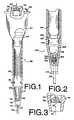
- Baster 100 employs the basic two parts as described heretofore in the prior art, a hollow tube 102 and a bulb 104. Both the hollow tube 102 and bulb 104 are provided with valves which work in conjunction with each other to produce several new and non-obvious results. It should be noted that other body configurations can be incorporated with the improvements disclosed herein, dependent upon end use. A conventional hollow, elongated tube is shown and described in detail herein, as this would be the most commonly used configuration. One example of an alternate used is illustrated in Figure 9 and, although not intended to limit the embodiments in any way, will give an example of alternate uses.
- the bulb 104 has been modified by the addition of a one-way air valve 120 installed at the top 103 of the bulb 104, as illustrated in further detail in Figure 3.
- the one-way valve 120 permits air to exit the bulb 104, as indicated by arrow 107.
- the materials of manufacture of the one-way valve is not narrowly critical and flexible rubber, silicone or other polymeric materials can be used.
- the one-way valve 120 can be formed integrally with the bulb 104, although other methods of manufacture can be utilized.
- the bulb design is similarly not narrowly critical and the bulb can be formed of the same or materials similar to those used to form the one-way valve 120.
- the bulb can be attached to the tube 102 and prevented from separating from the tube through use of a groove which cooperates with an annular ring 105 in the upper peripheral end of the tube 102.
- the connection design is not narrowly critical and other means, known in the art, can be used to attach the bulb 104 to the tube 102.
- the tube 102 is modified by the addition of a two-way liquid valve 109 that rests partially inside and partially outside of the tapered end 114.
- the special two-way liquid valve 109 consists of a valve body member 111 and a stem portion 110 and can be either a unitary member, or formed in parts, as described further herein.
- the liquid valve 109 is positioned inside the tapered end 114, of the tube 102 and conforms to the taper of the tapered end 114.
- the degree to which the body member 111 of the valve 109 and the interior surface 115 of the tapered end 114 conform is not narrowly critical. It is only critical that the body member 111 and the interior surface 115 have a region of equal diameter so that a seal can be formed and liquid flow past the sealed region restricted.
- the seal can be enhanced by the use of an O-ring as is well known in the art, or by having the taper, or contour, of the two surfaces close or the same.
- a restricting portion such as threaded screws 116 of Figure 1 or molded tabs 910 of Figure 9, extend into the tube 102 to prevent the valve 109 from sliding the entire length of the tube 102.
- the liquid valve 109 must be formed of an inert material having a higher specific gravity than that of the liquid which is being stored in the tube 102. Were the reverse true, the valve 109 would float in the liquid, thus opening the valve.
- the valve can be spring loaded to maintain the valve in the closed position.
- Such materials as brass and stainless steel can be used for the body member 111 and the stem 110 of the valve 109.
- the valve 109 can also be used with the two piece baster 200 as illustrated in Figure 2.
- the tube outlet tip 112 of the tapered end 114 of the tube 102 can be provided with one or a plurality of slits or notches 117 which provide for liquid communication between the exterior of the tube and the interior of the tube 102.
- the tip 112 is placed at the bottom of a vessel, thereby moving the stem 110 into the tube 102. Because of the contact between the tip 112 and the bottom of the vessel, flow can be restricted, depending upon the pressure placed on the tip 112. To maintain a maximum flow, the notches 117 allow for liquid to be drawn into the tube 102 even if the tip 112 is placed flush with the bottom of the vessel.
- the usual operation of the baster 100 of the present invention involves squeezing the bulb 104, thereby forcing air out of the baster 100.
- the device tube outlet tip 112 is inserted into the liquid to be drawn into the device.
- the pressure on the bulb 104 is then released and the liquid is thus drawn into the tube 102. If it is desired to draw additional liquid into the tube 102, the process can be repeated until a desired quantity is retained in the tube 102.
- the repetitive action is possible because the liquid valve 109 is forced against the interior surface 115 by the gravitational pressure of the liquid, thereby preventing the liquid from being expelled. Pressure from the heated air is eliminated as the built-up air pressure released through the upper one-way air valve 120, in the direction of arrow 107.
- the upper and lower valves act together to provide the desired result.
- the stem portion 110 is placed against the surface intended to receive the liquid. This action forces the stem portion 110 into a position flush with the tube outlet tip 112, raising the valve 109 into a position where the valve 109 is no longer blocking the tapered portion of the tube 102. In this manner the liquid valve 109 is opened and the liquid is discharged through the open end of the tube. If the surface tension or viscosity is sufficient to hold back the liquid, the bulb can be squeezed to force the liquid past the liquid valve 109 while maintaining continued contact between the stem portion 110 and the desired deposit location. As noted heretofore, excessive migration of the liquid valve 109 into the tube can be prevented, if so desired, by use of a restricting region, as disclosed herein.
- FIG 2 shows an alternate embodiment in which the baster 200 is manufactured in sections.
- the tube base 202 is attached to the tapered end 204 through threaded sections 208 and 206.
- the baster tube 200 can be easily opened for cleaning.
- the interior threading is illustrated in Figure 2 utilizes a smaller diameter tube base 202 with the wider tapered end 204, thereby preventing the liquid valve 209 from migrating to the top of the base 202.
- exterior thread designed is used which does not provide for the decrease of interior diameter
- screws 116 or tabs 910 of Figure 9 can be used to block the migration of the liquid valve 209.
- the baster 200 illustrated in Figure 2 utilizes a threaded connection, other means known in the art can be utilized to connect the tapered end 204 to the tube base 202.
- the alternate liquid valve 209 can be used with any of the tube embodiments illustrated herein.
- the stem portion 218 of the valve 209 can be removed from the valve body member 216 of the valve 209.
- the stem 218 is removably secured to the valve body member 216 by providing the stem portion 218 with threads 222 which mate with corresponding threads 214, on the interior of the stem-receiving-recess 220.
- the ability to remove the stem portion 218 from the valve body member 216 allows for an ease in cleaning.
- the air valve 120 of Figure 1 is shown in more detail in Figure 3, in which the air flow is indicated by the arrow 107.
- the valve 120 is provided with a flexible exterior body 108 and interior lips 106.
- the air passes through the space 122 between the lips 106, which flex when compressed and allow air to escape in the direction of the arrow 107. Pressure from the reverse direction does not cause lips 106 to separate, thereby resulting in a one-way valve.
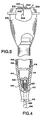
- the end of the stem portion 402 can be fitted with a round end ball 400 which is sufficiently large to restrict easy retraction into the open end of the tapered portion 414 of the baster.
- the stem 402 is dimensioned to provide only a small gap between the ball 400 and the baster tube rim 418 when the valve body member 411 is in contact with the interior surface 415 of the tube.
- the liquid valve can normally only move a small distance up and down in the tube.
- the ball 400 can be removably attached to the stem 402 to allow for easy removal of the ball 400 for cleaning.
- the diameter of the end ball 400 is such that it can be forced up into the tube to allow removal of the entire liquid valve for purposes of cleaning.
- the elongated tip or ball can be manufactured from any inert substance which can withstand the exposure to heat. This can include many types of metals, such as used for cooking pots. To decrease the risk of a burn due to contact with the tip of the baster a low conducting ceramic can be used.
- FIG. 5 a membrane 504 is placed over the vent hole 502 and secured to the bulb 500 at hinge 512.
- the hinge 512 is simply a self-hinge formed by affixing the membrane 504 to the bulb 500.
- the air is allowed to vent out the vent hole 502 in the direction of arrow 506.
- the membrane 504 Under extreme pressure, such as when the bulb is being squeezed, the membrane 504 will lift from the surface of the bulb 500. Air can also escape without the membrane 504 being lifted in the direction of arrow 508. Air is prevented by the membrane 504 from entering the bulb 500 through the vent hole 502, in the direction of arrow 510.
- valves 608 and 708 incorporate safety mechanisms to prevent the flow of hot liquid out of the one-way air valve should the user invert the baster, filling the bulb with hot liquid.
- the valve 608 incorporates a curved lid 604 affixed to a stem 610 which extends through the vent hole of the bulb 600. Within the bulb 600 the stem is affixed to a blocking plate 606 which, when the bulb 600 is inverted, prevents liquid from escaping through the vent hole. The air is allowed to escape on either side of the stem 610 in the direction of arrows 602.
- the valve 708 uses a ball top 704 rather than the curved lid 604.
- the valve 708 is also provided with a blocking plate 706 to prevent spillage. As with valve 608, the air is allowed to escape on either side of the valve in the direction of arrows 702. To provide for more convenient handling, it is preferable that the top of the bulb 700 be curved to allow for the ball top 704 to be recessed within the top.
- FIG. 8 An alternate air valve is illustrated in baster 800 of Figure 8 wherein the vent hole 806 is placed in the upper portion of the tube 812. A vent hole 806 is placed in the tube 812 and covered with a flexible band 810 which serves as a one way valve. When pressure is built up within the tube 812, the trapped air forces the band 810 to expand, allowing the air to be expelled in the direction of arrow 804. Air is prevented from entering the tube 812, in the direction 802, by the band 810.
- FIG. 9 An alternate to the tapered end is illustrated in Figure 9 wherein the tapered tip of the prior embodiments have been replaced with curved tip 902.
- the molded tabs 910 illustrated in this Figure, are used to maintain the liquid valve 904 in place.
- the molded tabs 910 replace the screws 116 illustrated in Figure 1 and can either be configured as a ring along the interior periphery or as tabs periodically extending into the interior of the body 906.
- the curved tip 902 is preferably in threaded connection with the body 906, as described in Figure 2.
- the threaded connection can either by flush, as illustrated, or graduated, as illustrated in Figure 2. In the event the graduated design used, the tabs 910 can be eliminated.
- the liquid valve 904 can be any of the designs described heretofore configured to the shape of the curved tip 902.
- the curved tip 902 provides the advantage that the valve 904 does not get lodged, or stick, within the tip 902.
- the body of the valve 904 must have a width greater than the liquid inlet 908 to prevent the valve 904 from migrating to the body 906.
- the operation of the device involves the steps of:
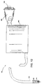
- FIG 10 illustrates an example .of an alternate use and design of the instant invention.
- the siphoning device 1000 comprises a flexible tube 1002, retaining receptacle 1006 and air pump 1008.
- the tube 1002 is provided with stop tabs 1010 which prevent the liquid valve 1004 from migrating into the retaining receptacle 1006.
- the air pump 1008 contains a one-way air valve 1012 which prevents air from entering the retaining receptacle.
- the end of the tube 1002, containing the liquid valve 1004 is placed in the liquid to be siphoned, such as oil from an engine.
- the air pump 1008 is activated, drawing the liquid up and into the retaining receptacle 1006.
- the retaining vessel 1006 is preferably manufactured with port 1014 to allow for easy emptying of the retaining vessel 1006.
- the design allows for the retaining vessel 1006 to be a size to accommodate the liquid to be stored.
- the tube 1002 is advantageous in siphoning liquids in hard to reach areas, such as engines, manufacturing equipment, etc.
- the exterior tube 1052 of the siphoning device 1050 is either removably connected, integral with, the interior tube 1064.
- the interior tube 1064 extends to the base of the container 1056.
- the exterior tube 1052 is placed within the liquid and the air pump 1058, containing one way air valve 1062, expels the air from the container 1056, drawing the fluid up the tube 1052.
- the stop tabs 1060 prevent the liquid valve 1054 from being pulled into the tube 1052.
- the container 1056 can alternatively be manufactured from a heavy duty coated cardboard which has been provided with perforations to receive the exterior tube 1052 and air pump 1058. This would allow for the removal of a substance such as oil from an engine, interior tube 1064 and air pump 1058 removed and the container taken for disposal. Plugs are preferably provided to prevent the contents from leaking out of the container 1056.
- Another safety-oriented variation for use with the bulb basters could be the use of a non-air tight cover or deflector to be placed at the top of the air valve to dilute the hot air being ejected from the bulb to preclude any chance of a user being met with hot air from the bulb. Further, a simple hand pump could be substituted for the rubber bulb.
Landscapes
- Engineering & Computer Science (AREA)
- Mechanical Engineering (AREA)
- Food Science & Technology (AREA)
- Containers And Packaging Bodies Having A Special Means To Remove Contents (AREA)
- Soy Sauces And Products Related Thereto (AREA)
- Jet Pumps And Other Pumps (AREA)
- Cyclones (AREA)
- Reciprocating Pumps (AREA)
Claims (9)
- Saughebevorrichtung (100, 200, 800, 900, 1000) für die Verwendung zum Begießen von Lebensmitteln mit einer heißen Flüssigkeit oder bei der Flüssigkeit/Flüssigkeit-Trennung, mit:einem Hohlkörperelement (102, 202, 410, 812, 1002), daswobei die Saughebevorrichtung ferner versehen ist mit:einen Auslaßbereich mit einer inneren kegelförmigen Oberfläche (114, 204, 414) und einem ersten offenen, spitzigen Ende (112, 212, 418, 902) mit einer Fluidströmungsöffnung, die eine radiale Abmessung besitzt, undeinen langgestreckten Körperbereich mit einem zweiten offenen Ende umfaßt,wobei das Zweiwege-Flüssigkeitsventil (109, 209, 411, 904, 1004) von einer ersten Position in eine zweite Position beweglich ist und mit der inneren kegelförmigen Oberfläche (114, 204, 414) des Auslaßbereichs in der Nähe des ersten offenen, spitzigen Endes (112, 212, 418, 902) in Eingriff gelangt, wenn es in der ersten Position ist, um dadurch von vornherein eine Fluidströmung aus dem Hohlkörperelement (102, 202, 410, 812, 1002) auszuschließen, und außer Eingriff mit der inneren kegelförmigen Oberfläche ( 114, 204, 414) des Auslaßbereichs gelangt, wenn es in der zweiten Position ist, um dadurch eine Strömung in das Hohlkörperelement (102, 202, 410, 812, 1002) und aus diesem zu ermöglichen, wobei der Schaftabschnitt (110, 218, 402, 904) ein erstes Ende und ein zweites Ende besitzt und an dem Ventilkörperelement (111, 216, 411) mit dem ersten Ende befestigt ist, um sich zusammen mit dem Ventilkörperelement (111, 216, 411) zu bewegen, wobei die Länge des Schaftabschnitts (110, 218, 402, 904) wesentlich größer als die radiale Abmessung der Fluidströmungsöffnung des ersten offenen, spitzigen Endes (112, 212, 418, 902) ist,einem Zweiwege-Flüssigkeitsventil (109, 209, 411, 904, 1004), das im Auslaßbereich in der Nähe des ersten offenen, spitzigen Endes ( 112, 212, 418, 902) positioniert ist und einen langgestreckten Schaftabschnitt ( 110, 218, 402, 904) und ein Ventilkörperelement (111, 216, 411), das in dem Auslaßbereich beweglich positioniert ist, besitzt, undLuftpumpmitteln (104, 500, 600, 700, 1008), die mit dem zweiten Ende des Hohlkörperelements (102, 202, 410, 812, 1002) zusammenwirkt, um Luft aus dem Hohlkörperelement (102, 202, 410, 812, 1002) auszustoßen und Flüssigkeit in das Hohlkörperelement (102, 202, 410, 812, 1002) anzusaugen,
wobei sich der Schaftabschnitt (110, 218, 402, 904) dann, wenn sich das Ventilkörperelement (111, 216, 411) in der ersten Position befindet, durch das offene, spitzige Ende ( 112, 212, 418, 902) und im wesentlichen darüber hinaus erstreckt und das Ventilkörperelement (111, 216, 411) dann, wenn das zweite Ende des Schaftabschnitts (110, 218, 402, 904) zu dem offenen, spitzigen Ende (112, 212, 418, 902) des Auslaßbereichs bewegt wird, von der inneren kegelförmigen Oberfläche (114, 204, 414) des Auslaßbereichs um eine Strecke wegbewegt wird, die wesentlich größer als die radiale Abmessung der Fluidströmungsöffnung ist, und eine allmählich sich vergrößernde Öffnung und eine axiale Flüssigkeitsströmung aus dem offenen, spitzigen Ende (112, 212, 418, 902) und am Schaftabschnitt ( 110, 218, 402, 904) vorbei geschaffen wird;
und wobei der Druck auf den Schaftabschnitt (110, 218, 402, 904) in Richtung des Ventilkörperelements (111, 216, 411) das Ventilkörperelement (111, 216, 411) außer Kontakt mit der Innenwand bewegt, wodurch das Flüssigkeitsventil (109, 209, 411, 904, 1004) in einer geöffneten Position angeordnet wird, so daß Flüssigkeit aus dem Hohlkörperelement (102, 202, 410, 812, 1002) axial durch die Fluidströmungsöffnung des ersten offenen, spitzigen Endes (112, 212, 418, 902) und längs des Schaftabschnitts (110, 218, 402, 904) entleert werden kann, dadurch gekennzeichnet, daß sie ferner ein Einweg-Luftventil (120, 504, 608, 708, 810, 1012) umfaßt, das mit den Luftpumpmitteln (104, 500, 600, 700, 1008) in Wechselwirkung steht, wobei das Einweg-Luftventil (120, 504, 608, 708, 810, 1012) die Luftströmung in das Hohlkörperelement (102, 202, 410, 812, 1002) begrenzt und eine Luftströmung aus dem Hohlkörperelement (102, 202, 410, 812, 1002) zuläßt. - Saughebevorrichtung (100, 200, 800, 900, 1000) nach Anspruch 1, bei der das Flüssigkeits-Ventilkörperelement (111, 216, 411) ein spezifisches Gewicht besitzt, das wesentlich größer als dasjenige der zu trennenden Flüssigkeiten ist.
- Saughebevorrichtung (100, 200, 800, 900, 1000) nach Anspruch 1, bei der der Auslaßbereich ferner einen Umfangsrand in der Nähe des offenen, spitzigen Endes (112) aufweist, der Kerben (117) besitzt, die sich von der Innenseite zur Außenseite des Auslaßbereichs erstrecken, um einen Flüssigkeitsdurchgang in das Hohlkörperelement (102) zuzulassen.
- Saughebevorrichtung (100, 200, 800, 900, 1000) nach Anspruch 1, bei der die Luftpumpmittel (104, 500, 600, 700, 1008) ein flexibler Kolben sind, der am zweiten offenen Ende des Hohlkörperelements (102, 202, 410, 812, 1002) befestigt ist.
- Saughebevorrichtung (100, 200, 800, 900, 1000) nach Anspruch 1, die ferner Anschlagmittel (400) umfaßt, die sich an dem Endabschnitt des Schaftabschnitts (402) befinden und einen Durchmesser besitzen, der größer als der Durchmesser der Fluidströmungsöffnung ist.
- Saughebevorrichtung nach Anspruch 5, bei der die Bewegung des Flüssigkeits-Ventilkörperelements (411) in die geöffnete Position durch die Anschlagmittel (400) begrenzt ist.
- Saughebevorrichtung (100, 200, 800, 900, 1000) nach Anspruch 1, die ferner einen Begrenzungsabschnitt (116, 910, 1010) umfaßt, der die Bewegung des Flüssigkeitskörperelements (111, 216, 411) zu dem zweiten offenen Ende des langgestreckten Körperbereichs verhindert.
- Verfahren zur Trennung und Übertragung von Flüssigkeit unter Verwendung einer Vorrichtung (100, 200, 800, 900, 1000), die versehen ist mit einem Hohlkörperelement (102, 202, 410, 812, 1002), das ein offenes, spitziges Ende ( 112, 212, 418, 902) und ein Zweiwege-Flüssigkeitsventil (109, 209, 411, 904, 1004), das in einer inneren kegelförmigen Oberfläche (115, 204, 414) positioniert ist und eine Flüssigkeitsströmung aus dem Hohlkörperelement (102, 202, 410, 812, 1002) begrenzt und die Strömung von Flüssigkeit in das Hohlkörperelement (102, 202, 410, 812, 1002) zuläßt, umfaßt, Luftpumpmitteln (104, 500, 600, 700, 1008) und einem Einweg-Luftventil (120, 504, 608, 708, 810, 1012) in der Nähe der Luftpumpmittel (104, 500, 600, 700, 1008), wobei die Luftpumpmittel (104, 500, 600, 700, 1008) mit dem Hohlkörperelement (102, 202, 410, 812, 1002) in Wechselwirkung treten, um Luft aus dem Hohlkörperelement (102, 202, 410, 812, 1002) auszustoßen, und das Luftventil (120, 504, 608, 708, 810, 1012) eine Luftströmung in das Hohlelement (102, 202, 410, 812, 1002) verhindert und eine Luftströmung aus dem Hohlkörperelement (102, 202, 410, 812, 1002) zuläßt, umfassend die folgenden Schritte:dadurch gekennzeichnet, daß es ferner die folgenden Schritte umfaßt:Pumpen von Luft aus der Vorrichtung (100, 200, 800, 900, 1000) durch die Luftpumpmittel (104, 500, 600, 700, 1008) durch Einschnüren der Luftpumpmittel (104, 500, 600, 700, 800),Einsetzen des offenen, spitzigen Endes (112, 212, 418, 902) in eine Flüssigkeit, derart, daß sich das offene spitzige Ende (112, 212, 418, 902) unterhalb der Oberfläche der Flüssigkeit befindet,Heben von Flüssigkeit durch Saugen in die Vorrichtung (100, 200, 800, 900, 1000) durch Freigeben der Luftpumpmittel (104, 500, 600, 700, 1008), wobei durch das Luftventil (120, 504, 608, 708, 810, 1012) verhindert wird, daß Luft in das Hohlkörperelement (102, 202, 410, 812, 1002) eintritt,Zurückziehen des offenen, spitzigen Endes (112, 212, 418, 902) aus der Flüssigkeit, wobei das Zweiwege-Flüssigkeitsventil (109, 209, 411, 904, 1004) die Strömung von Flüssigkeit aus der Vorrichtung (100, 200, 800, 900, 1000) beschränkt,Bewegen der Vorrichtung (100, 200, 800, 900, 1000) an einen gewünschten Ort,Betätigen des Flüssigkeitsventils (109, 209, 411, 904, 1004), um eine Strömung der Flüssigkeit aus dem Hohlkörperelement (102, 202, 410, 812, 1002) an den gewünschten Ort zuzulassen und dadurch wenigstens einen Teil der Flüssigkeit an den gewünschten Ort abzugeben,wiederholtes Betätigen der Luftpumpe (104, 500, 600, 700, 1008), während sich das offene, spitzige Ende (112, 212, 418, 902) unterhalb der Oberfläche der Flüssigkeit befindet, wobei das Flüssigkeitsventil (109, 209, 411, 904, 1004) verhindert, daß Flüssigkeit von der Vorrichtung (100, 200, 800, 900, 1000) ausströmt, während es eine Fluidströmung in die Vorrichtung (100, 200, 800, 900, 1000) zuläßt, und wobei das Einweg-Luftventil (120, 504, 608, 708, 810, 1012) eine Luftströmung aus dem Hohlkörperelement (102, 202, 410, 812, 1002) ermöglicht, während es ein Eintreten von Luft in das Hohlkörperelement (102, 202, 410, 812, 1002) verhindert, wodurch wiederholt Flüssigkeit in die Vorrichtung (100, 200, 800, 900, 1000) gesaugt wird.
- Verfahren nach Anspruch 8, bei dem die Flüssigkeit mehrere unvermischbare Flüssigkeiten umfaßt und das ferner den Schritt des sukzessiven Trennens wenigstens zweier der unvermischbaren Flüssigkeiten in getrennte Behälter umfaßt, um dadurch die unvermischbaren Flüssigkeiten zu trennen.
Applications Claiming Priority (2)
| Application Number | Priority Date | Filing Date | Title |
|---|---|---|---|
| US08/518,006 US5638872A (en) | 1995-08-22 | 1995-08-22 | Siphoning device for use in basting, measuring or immiscible liquid separation |
| PCT/US1997/010455 WO1998057574A1 (en) | 1995-08-22 | 1997-06-17 | Siphoning device for use in liquid basting and separation |
Publications (3)
| Publication Number | Publication Date |
|---|---|
| EP0983012A1 EP0983012A1 (de) | 2000-03-08 |
| EP0983012A4 EP0983012A4 (de) | 2000-04-05 |
| EP0983012B1 true EP0983012B1 (de) | 2003-12-03 |
Family
ID=26792573
Family Applications (1)
| Application Number | Title | Priority Date | Filing Date |
|---|---|---|---|
| EP97932193A Expired - Lifetime EP0983012B1 (de) | 1995-08-22 | 1997-06-17 | Siphon-vorrichtung zum begiessen und abscheiden von flüssigkeit. |
Country Status (6)
| Country | Link |
|---|---|
| US (1) | US5638872A (de) |
| EP (1) | EP0983012B1 (de) |
| AT (1) | ATE255352T1 (de) |
| AU (1) | AU3571597A (de) |
| DE (1) | DE69726616T2 (de) |
| WO (1) | WO1998057574A1 (de) |
Families Citing this family (19)
| Publication number | Priority date | Publication date | Assignee | Title |
|---|---|---|---|---|
| US5720330A (en) * | 1997-01-23 | 1998-02-24 | Schmalz, Jr.; John W. | Squeeze bulb for liquid extraction device |
| US6634393B2 (en) | 2000-08-16 | 2003-10-21 | Jerry Porter | Siphoning device for use in basting, measuring or immiscible liquid separation |
| US6412528B1 (en) * | 2000-09-19 | 2002-07-02 | Peter Alex | Siphoning pump apparatus |
| US6782803B2 (en) | 2001-01-11 | 2004-08-31 | Hutzler Manufacturing Co., Inc. | Method of and device for basting |
| US6457400B1 (en) * | 2001-01-11 | 2002-10-01 | Hutzler Manufacturing Co., Inc. | Baster |
| US7140069B1 (en) | 2002-07-19 | 2006-11-28 | Dangerfield John N | Grease extractor |
| CA2425350A1 (en) * | 2003-04-14 | 2004-10-14 | Peter Alex | Container shut-off valve with venting |
| CA2441991C (en) * | 2003-09-19 | 2012-11-13 | Ronald R. Chisholm | Fluid transfer apparatus |
| US20050115606A1 (en) * | 2003-10-01 | 2005-06-02 | Chisholm Ronald R. | System for effecting liquid transfer from an elevated supply container |
| WO2005082214A1 (en) * | 2004-02-25 | 2005-09-09 | Andhow Innovations, Llc. | Leak resistant siphoning device for use in fluid transfer |
| US7819293B1 (en) | 2004-05-19 | 2010-10-26 | O'connell Thomas P | Replenishable drinking vessel |
| US20070181007A1 (en) * | 2006-02-09 | 2007-08-09 | Browne & Co. | Basting device |
| US20080240841A1 (en) * | 2007-03-28 | 2008-10-02 | Helen Of Troy Limited | Fluid dispensing apparatus |
| USD611310S1 (en) * | 2009-03-21 | 2010-03-09 | Wki Holding Company, Inc. | Meat injector |
| USD640902S1 (en) * | 2010-09-12 | 2011-07-05 | Timothy Corcoran Repp | Bulb actuated suction device |
| US8683914B1 (en) * | 2011-03-11 | 2014-04-01 | Fox Run Usa, Llc | Baster and method |
| ES3033914T3 (en) * | 2015-10-21 | 2025-08-11 | Boehringer Ingelheim Vetmedica Gmbh | Storage and dispenser device |
| USD878877S1 (en) | 2018-09-26 | 2020-03-24 | Venturi, Llc | Meat injector |
| US11350793B2 (en) | 2018-12-19 | 2022-06-07 | Michael J. Alvarez | Meat injector |
Family Cites Families (23)
| Publication number | Priority date | Publication date | Assignee | Title |
|---|---|---|---|---|
| USRE15017E (en) * | 1920-12-28 | somerville | ||
| US972075A (en) * | 1909-11-18 | 1910-10-04 | George M Freeman | Cream-collecting pump. |
| US1036822A (en) * | 1911-12-04 | 1912-08-27 | George M Freeman | Combined pump and pitcher. |
| US1106937A (en) * | 1912-12-19 | 1914-08-11 | Abbot Porter Goff | Automatic reacting siphon air-pump and stopper. |
| US1263453A (en) * | 1917-02-07 | 1918-04-23 | William W Medley | Cream-extractor. |
| US1977062A (en) * | 1932-05-24 | 1934-10-16 | James C Kilburn | Cream extractor |
| US2234884A (en) * | 1939-03-03 | 1941-03-11 | Florence M Teel | Basting device |
| US2243908A (en) * | 1940-05-01 | 1941-06-03 | Kassab Wadea | Self-filling syringe |
| US2489035A (en) * | 1948-02-27 | 1949-11-22 | Jones Richard O'd | Shock absorber fluid dispensing and metering device |
| US3171446A (en) * | 1963-02-11 | 1965-03-02 | Delman Co | Fluid dispenser and container |
| US3713378A (en) * | 1971-02-18 | 1973-01-30 | Cobb J | Baster and tenderizer |
| US3908532A (en) * | 1974-09-30 | 1975-09-30 | Paul W Underwood | Automatic baster cooker |
| USD245140S (en) | 1975-07-14 | 1977-07-26 | Benson William E | Butter baster |
| US4066010A (en) * | 1977-01-27 | 1978-01-03 | Kim Larsson | Automatic baster |
| US4177721A (en) * | 1978-02-01 | 1979-12-11 | Redhead Walden K | Barbecue rotisserie baster |
| US4129066A (en) * | 1978-02-03 | 1978-12-12 | Corley John C | Basting device |
| NL8600111A (nl) * | 1986-01-20 | 1987-08-17 | Bernardus Johannes Josephus Au | Stop voor een houder, zoals een fles en een daarop aansluitbare pomp voor het afzuigen resp. inpersen van gasvormig medium uit resp. in de houder. |
| US4968298A (en) * | 1988-09-12 | 1990-11-06 | Michelson Gary K | Interspace irrigator |
| US4979944A (en) * | 1989-08-21 | 1990-12-25 | The Pullman Company | Surgical vacuum evacuation device |
| US5244021A (en) * | 1991-12-13 | 1993-09-14 | Hau Ernest F | Fuel transfer container |
| US5408919A (en) * | 1993-03-02 | 1995-04-25 | Hutzler Manufacturing Company Inc. | Baster |
| US5394789A (en) * | 1993-07-08 | 1995-03-07 | Evans; John P. | Manually operable device for metering air through a valve system for drawing into, retaining and evacuating material from a chamber |
| DE9400551U1 (de) * | 1994-01-14 | 1994-05-05 | Stasch, Günter, 76761 Rülzheim | Saucen-Sauger |
-
1995
- 1995-08-22 US US08/518,006 patent/US5638872A/en not_active Expired - Lifetime
-
1997
- 1997-06-17 DE DE69726616T patent/DE69726616T2/de not_active Expired - Lifetime
- 1997-06-17 WO PCT/US1997/010455 patent/WO1998057574A1/en not_active Ceased
- 1997-06-17 AU AU35715/97A patent/AU3571597A/en not_active Abandoned
- 1997-06-17 EP EP97932193A patent/EP0983012B1/de not_active Expired - Lifetime
- 1997-06-17 AT AT97932193T patent/ATE255352T1/de not_active IP Right Cessation
Also Published As
| Publication number | Publication date |
|---|---|
| DE69726616T2 (de) | 2004-09-30 |
| ATE255352T1 (de) | 2003-12-15 |
| EP0983012A1 (de) | 2000-03-08 |
| US5638872A (en) | 1997-06-17 |
| AU3571597A (en) | 1999-01-04 |
| HK1026830A1 (en) | 2000-12-29 |
| DE69726616D1 (de) | 2004-01-15 |
| WO1998057574A1 (en) | 1998-12-23 |
| EP0983012A4 (de) | 2000-04-05 |
Similar Documents
| Publication | Publication Date | Title |
|---|---|---|
| EP0983012B1 (de) | Siphon-vorrichtung zum begiessen und abscheiden von flüssigkeit. | |
| US5875823A (en) | Siphoning device for use in basting, measuring or immiscible liquid separation | |
| CA1302370C (en) | Method and apparatus for dispensing liquids | |
| US4875603A (en) | Metered dispensing cap for tubes | |
| CA2064905C (en) | Device for dispensing flowing substances | |
| AU749233B2 (en) | Combined measuring cup, funnel and strainer utensil | |
| JPH0364122B2 (de) | ||
| US4211346A (en) | Variable volume dispensing bottle with push-pull closure | |
| EP2491814A1 (de) | Flüssigkeitstropfer mit dosierter entnahme und damit ausgestatteter kosmetisches behälter | |
| US4856677A (en) | Portioning device for paste or semi-liquid products | |
| JP3905934B2 (ja) | 容器に装着可能な液量装置 | |
| JPH0825569B2 (ja) | 液状またはペ−スト状内容物に用いる使い捨て型デイスペンサ−ポンプ | |
| CN111918824B (zh) | 液体容器用定量排出装置 | |
| CA2097283C (en) | Tube liquid dispenser | |
| US6702160B1 (en) | No spill container | |
| US5394789A (en) | Manually operable device for metering air through a valve system for drawing into, retaining and evacuating material from a chamber | |
| US4535918A (en) | Dispenser with squeeze-bulb actuator | |
| US5624059A (en) | Device for dispensing corrosive liquids accurately and without contamination | |
| HK1026830B (en) | Siphoning device for use in liquid basting and separation | |
| US3763903A (en) | Funnels | |
| JPH0672791B2 (ja) | 大容量の深い容器から吸引容器によって液体を取出す方法、及びこの方法を実施するための大容量の深い容器に対する吸引補助手段としての装置 | |
| US6634393B2 (en) | Siphoning device for use in basting, measuring or immiscible liquid separation | |
| CA2282857C (en) | Siphoning device for use in liquid basting and separation | |
| US20080202631A1 (en) | Leak Resistant Siphoning Device For Use in Fluid Transfer | |
| GB2304825A (en) | Dispenser for edible food spreads |
Legal Events
| Date | Code | Title | Description |
|---|---|---|---|
| PUAI | Public reference made under article 153(3) epc to a published international application that has entered the european phase |
Free format text: ORIGINAL CODE: 0009012 |
|
| 17P | Request for examination filed |
Effective date: 19990924 |
|
| AK | Designated contracting states |
Kind code of ref document: A1 Designated state(s): AT BE CH DE DK ES FI FR GB GR IE IT LI LU MC NL PT SE |
|
| A4 | Supplementary search report drawn up and despatched |
Effective date: 20000218 |
|
| AK | Designated contracting states |
Kind code of ref document: A4 Designated state(s): AT BE CH DE DK ES FI FR GB GR IE IT LI LU MC NL PT SE |
|
| RIC1 | Information provided on ipc code assigned before grant |
Free format text: 7A 47J 37/00 A, 7A 47J 37/10 B |
|
| 17Q | First examination report despatched |
Effective date: 20020409 |
|
| RAP1 | Party data changed (applicant data changed or rights of an application transferred) |
Owner name: PORTER, JERRY |
|
| RIN1 | Information on inventor provided before grant (corrected) |
Inventor name: PORTER, JERRY |
|
| GRAH | Despatch of communication of intention to grant a patent |
Free format text: ORIGINAL CODE: EPIDOS IGRA |
|
| GRAS | Grant fee paid |
Free format text: ORIGINAL CODE: EPIDOSNIGR3 |
|
| GRAA | (expected) grant |
Free format text: ORIGINAL CODE: 0009210 |
|
| RAP1 | Party data changed (applicant data changed or rights of an application transferred) |
Owner name: NATIONAL SAFETY ADVISORS, INC. |
|
| RIN1 | Information on inventor provided before grant (corrected) |
Inventor name: PORTER, JERRY |
|
| AK | Designated contracting states |
Kind code of ref document: B1 Designated state(s): AT BE CH DE DK ES FI FR GB GR IE IT LI LU MC NL PT SE |
|
| PG25 | Lapsed in a contracting state [announced via postgrant information from national office to epo] |
Ref country code: NL Free format text: LAPSE BECAUSE OF FAILURE TO SUBMIT A TRANSLATION OF THE DESCRIPTION OR TO PAY THE FEE WITHIN THE PRESCRIBED TIME-LIMIT Effective date: 20031203 Ref country code: LI Free format text: LAPSE BECAUSE OF FAILURE TO SUBMIT A TRANSLATION OF THE DESCRIPTION OR TO PAY THE FEE WITHIN THE PRESCRIBED TIME-LIMIT Effective date: 20031203 Ref country code: FI Free format text: LAPSE BECAUSE OF FAILURE TO SUBMIT A TRANSLATION OF THE DESCRIPTION OR TO PAY THE FEE WITHIN THE PRESCRIBED TIME-LIMIT Effective date: 20031203 Ref country code: CH Free format text: LAPSE BECAUSE OF FAILURE TO SUBMIT A TRANSLATION OF THE DESCRIPTION OR TO PAY THE FEE WITHIN THE PRESCRIBED TIME-LIMIT Effective date: 20031203 Ref country code: BE Free format text: LAPSE BECAUSE OF FAILURE TO SUBMIT A TRANSLATION OF THE DESCRIPTION OR TO PAY THE FEE WITHIN THE PRESCRIBED TIME-LIMIT Effective date: 20031203 Ref country code: AT Free format text: LAPSE BECAUSE OF FAILURE TO SUBMIT A TRANSLATION OF THE DESCRIPTION OR TO PAY THE FEE WITHIN THE PRESCRIBED TIME-LIMIT Effective date: 20031203 |
|
| REG | Reference to a national code |
Ref country code: GB Ref legal event code: FG4D |
|
| REG | Reference to a national code |
Ref country code: CH Ref legal event code: EP |
|
| REG | Reference to a national code |
Ref country code: IE Ref legal event code: FG4D |
|
| REF | Corresponds to: |
Ref document number: 69726616 Country of ref document: DE Date of ref document: 20040115 Kind code of ref document: P |
|
| PG25 | Lapsed in a contracting state [announced via postgrant information from national office to epo] |
Ref country code: SE Free format text: LAPSE BECAUSE OF FAILURE TO SUBMIT A TRANSLATION OF THE DESCRIPTION OR TO PAY THE FEE WITHIN THE PRESCRIBED TIME-LIMIT Effective date: 20040303 Ref country code: GR Free format text: LAPSE BECAUSE OF FAILURE TO SUBMIT A TRANSLATION OF THE DESCRIPTION OR TO PAY THE FEE WITHIN THE PRESCRIBED TIME-LIMIT Effective date: 20040303 Ref country code: DK Free format text: LAPSE BECAUSE OF FAILURE TO SUBMIT A TRANSLATION OF THE DESCRIPTION OR TO PAY THE FEE WITHIN THE PRESCRIBED TIME-LIMIT Effective date: 20040303 |
|
| PG25 | Lapsed in a contracting state [announced via postgrant information from national office to epo] |
Ref country code: ES Free format text: LAPSE BECAUSE OF FAILURE TO SUBMIT A TRANSLATION OF THE DESCRIPTION OR TO PAY THE FEE WITHIN THE PRESCRIBED TIME-LIMIT Effective date: 20040314 |
|
| NLV1 | Nl: lapsed or annulled due to failure to fulfill the requirements of art. 29p and 29m of the patents act | ||
| REG | Reference to a national code |
Ref country code: CH Ref legal event code: PL |
|
| PG25 | Lapsed in a contracting state [announced via postgrant information from national office to epo] |
Ref country code: LU Free format text: LAPSE BECAUSE OF NON-PAYMENT OF DUE FEES Effective date: 20040617 Ref country code: IE Free format text: LAPSE BECAUSE OF NON-PAYMENT OF DUE FEES Effective date: 20040617 Ref country code: GB Free format text: LAPSE BECAUSE OF NON-PAYMENT OF DUE FEES Effective date: 20040617 |
|
| PG25 | Lapsed in a contracting state [announced via postgrant information from national office to epo] |
Ref country code: MC Free format text: LAPSE BECAUSE OF NON-PAYMENT OF DUE FEES Effective date: 20040630 |
|
| ET | Fr: translation filed | ||
| PLBE | No opposition filed within time limit |
Free format text: ORIGINAL CODE: 0009261 |
|
| STAA | Information on the status of an ep patent application or granted ep patent |
Free format text: STATUS: NO OPPOSITION FILED WITHIN TIME LIMIT |
|
| 26N | No opposition filed |
Effective date: 20040906 |
|
| REG | Reference to a national code |
Ref country code: HK Ref legal event code: GR Ref document number: 1026830 Country of ref document: HK |
|
| GBPC | Gb: european patent ceased through non-payment of renewal fee |
Effective date: 20040617 |
|
| REG | Reference to a national code |
Ref country code: IE Ref legal event code: MM4A |
|
| PG25 | Lapsed in a contracting state [announced via postgrant information from national office to epo] |
Ref country code: PT Free format text: LAPSE BECAUSE OF NON-PAYMENT OF DUE FEES Effective date: 20040503 |
|
| PGFP | Annual fee paid to national office [announced via postgrant information from national office to epo] |
Ref country code: FR Payment date: 20110629 Year of fee payment: 15 |
|
| PGFP | Annual fee paid to national office [announced via postgrant information from national office to epo] |
Ref country code: DE Payment date: 20110629 Year of fee payment: 15 |
|
| PGFP | Annual fee paid to national office [announced via postgrant information from national office to epo] |
Ref country code: IT Payment date: 20110628 Year of fee payment: 15 |
|
| PG25 | Lapsed in a contracting state [announced via postgrant information from national office to epo] |
Ref country code: IT Free format text: LAPSE BECAUSE OF NON-PAYMENT OF DUE FEES Effective date: 20120617 |
|
| REG | Reference to a national code |
Ref country code: FR Ref legal event code: ST Effective date: 20130228 |
|
| PG25 | Lapsed in a contracting state [announced via postgrant information from national office to epo] |
Ref country code: DE Free format text: LAPSE BECAUSE OF NON-PAYMENT OF DUE FEES Effective date: 20130101 Ref country code: FR Free format text: LAPSE BECAUSE OF NON-PAYMENT OF DUE FEES Effective date: 20120702 |
|
| REG | Reference to a national code |
Ref country code: DE Ref legal event code: R119 Ref document number: 69726616 Country of ref document: DE Effective date: 20130101 |