EP0982465A2 - Protective device for an overhead door - Google Patents
Protective device for an overhead door Download PDFInfo
- Publication number
- EP0982465A2 EP0982465A2 EP99116577A EP99116577A EP0982465A2 EP 0982465 A2 EP0982465 A2 EP 0982465A2 EP 99116577 A EP99116577 A EP 99116577A EP 99116577 A EP99116577 A EP 99116577A EP 0982465 A2 EP0982465 A2 EP 0982465A2
- Authority
- EP
- European Patent Office
- Prior art keywords
- frame
- door leaf
- protection device
- fastening
- protective
- Prior art date
- Legal status (The legal status is an assumption and is not a legal conclusion. Google has not performed a legal analysis and makes no representation as to the accuracy of the status listed.)
- Granted
Links
Images


Classifications
-
- E—FIXED CONSTRUCTIONS
- E05—LOCKS; KEYS; WINDOW OR DOOR FITTINGS; SAFES
- E05D—HINGES OR SUSPENSION DEVICES FOR DOORS, WINDOWS OR WINGS
- E05D13/00—Accessories for sliding or lifting wings, e.g. pulleys, safety catches
- E05D13/10—Counterbalance devices
- E05D13/12—Counterbalance devices with springs
- E05D13/1207—Counterbalance devices with springs with tension springs
- E05D13/1215—Counterbalance devices with springs with tension springs specially adapted for overhead wings
-
- E—FIXED CONSTRUCTIONS
- E05—LOCKS; KEYS; WINDOW OR DOOR FITTINGS; SAFES
- E05D—HINGES OR SUSPENSION DEVICES FOR DOORS, WINDOWS OR WINGS
- E05D15/00—Suspension arrangements for wings
- E05D15/40—Suspension arrangements for wings supported on arms movable in vertical planes
- E05D15/42—Suspension arrangements for wings supported on arms movable in vertical planes with pivoted arms and horizontally-sliding guides
- E05D15/425—Suspension arrangements for wings supported on arms movable in vertical planes with pivoted arms and horizontally-sliding guides specially adapted for overhead wings
-
- E—FIXED CONSTRUCTIONS
- E06—DOORS, WINDOWS, SHUTTERS, OR ROLLER BLINDS IN GENERAL; LADDERS
- E06B—FIXED OR MOVABLE CLOSURES FOR OPENINGS IN BUILDINGS, VEHICLES, FENCES OR LIKE ENCLOSURES IN GENERAL, e.g. DOORS, WINDOWS, BLINDS, GATES
- E06B1/00—Border constructions of openings in walls, floors, or ceilings; Frames to be rigidly mounted in such openings
- E06B1/04—Frames for doors, windows, or the like to be fixed in openings
- E06B1/52—Frames specially adapted for doors
- E06B1/522—Frames specially adapted for doors for overhead garage doors
-
- E—FIXED CONSTRUCTIONS
- E06—DOORS, WINDOWS, SHUTTERS, OR ROLLER BLINDS IN GENERAL; LADDERS
- E06B—FIXED OR MOVABLE CLOSURES FOR OPENINGS IN BUILDINGS, VEHICLES, FENCES OR LIKE ENCLOSURES IN GENERAL, e.g. DOORS, WINDOWS, BLINDS, GATES
- E06B7/00—Special arrangements or measures in connection with doors or windows
- E06B7/16—Sealing arrangements on wings or parts co-operating with the wings
- E06B7/22—Sealing arrangements on wings or parts co-operating with the wings by means of elastic edgings, e.g. elastic rubber tubes; by means of resilient edgings, e.g. felt or plush strips, resilient metal strips
- E06B7/23—Plastic, sponge rubber, or like strips or tubes
- E06B7/2305—Plastic, sponge rubber, or like strips or tubes with an integrally formed part for fixing the edging
- E06B7/2307—Plastic, sponge rubber, or like strips or tubes with an integrally formed part for fixing the edging with a single sealing-line or -plane between the wing and the part co-operating with the wing
- E06B7/231—Plastic, sponge rubber, or like strips or tubes with an integrally formed part for fixing the edging with a single sealing-line or -plane between the wing and the part co-operating with the wing with a solid sealing part
-
- E—FIXED CONSTRUCTIONS
- E06—DOORS, WINDOWS, SHUTTERS, OR ROLLER BLINDS IN GENERAL; LADDERS
- E06B—FIXED OR MOVABLE CLOSURES FOR OPENINGS IN BUILDINGS, VEHICLES, FENCES OR LIKE ENCLOSURES IN GENERAL, e.g. DOORS, WINDOWS, BLINDS, GATES
- E06B7/00—Special arrangements or measures in connection with doors or windows
- E06B7/28—Other arrangements on doors or windows, e.g. door-plates, windows adapted to carry plants, hooks for window cleaners
- E06B7/36—Finger guards or other measures preventing harmful access between the door and the door frame
-
- E—FIXED CONSTRUCTIONS
- E05—LOCKS; KEYS; WINDOW OR DOOR FITTINGS; SAFES
- E05D—HINGES OR SUSPENSION DEVICES FOR DOORS, WINDOWS OR WINGS
- E05D13/00—Accessories for sliding or lifting wings, e.g. pulleys, safety catches
- E05D13/10—Counterbalance devices
- E05D13/12—Counterbalance devices with springs
- E05D13/1207—Counterbalance devices with springs with tension springs
- E05D13/1223—Spring safety devices
-
- E—FIXED CONSTRUCTIONS
- E05—LOCKS; KEYS; WINDOW OR DOOR FITTINGS; SAFES
- E05Y—INDEXING SCHEME RELATING TO HINGES OR OTHER SUSPENSION DEVICES FOR DOORS, WINDOWS OR WINGS AND DEVICES FOR MOVING WINGS INTO OPEN OR CLOSED POSITION, CHECKS FOR WINGS AND WING FITTINGS NOT OTHERWISE PROVIDED FOR, CONCERNED WITH THE FUNCTIONING OF THE WING
- E05Y2201/00—Constructional elements; Accessories therefore
- E05Y2201/40—Motors; Magnets; Springs; Weights; Accessories therefore
- E05Y2201/47—Springs; Spring tensioners
- E05Y2201/488—Traction springs
-
- E—FIXED CONSTRUCTIONS
- E05—LOCKS; KEYS; WINDOW OR DOOR FITTINGS; SAFES
- E05Y—INDEXING SCHEME RELATING TO HINGES OR OTHER SUSPENSION DEVICES FOR DOORS, WINDOWS OR WINGS AND DEVICES FOR MOVING WINGS INTO OPEN OR CLOSED POSITION, CHECKS FOR WINGS AND WING FITTINGS NOT OTHERWISE PROVIDED FOR, CONCERNED WITH THE FUNCTIONING OF THE WING
- E05Y2800/00—Details, accessories and auxiliary operations not otherwise provided for
- E05Y2800/20—Combinations of elements
- E05Y2800/21—Combinations of elements of identical elements, e.g. of identical compression springs
-
- E—FIXED CONSTRUCTIONS
- E05—LOCKS; KEYS; WINDOW OR DOOR FITTINGS; SAFES
- E05Y—INDEXING SCHEME RELATING TO HINGES OR OTHER SUSPENSION DEVICES FOR DOORS, WINDOWS OR WINGS AND DEVICES FOR MOVING WINGS INTO OPEN OR CLOSED POSITION, CHECKS FOR WINGS AND WING FITTINGS NOT OTHERWISE PROVIDED FOR, CONCERNED WITH THE FUNCTIONING OF THE WING
- E05Y2800/00—Details, accessories and auxiliary operations not otherwise provided for
- E05Y2800/69—Permanence of use
- E05Y2800/696—Permanence of use during transport or storage
-
- E—FIXED CONSTRUCTIONS
- E05—LOCKS; KEYS; WINDOW OR DOOR FITTINGS; SAFES
- E05Y—INDEXING SCHEME RELATING TO HINGES OR OTHER SUSPENSION DEVICES FOR DOORS, WINDOWS OR WINGS AND DEVICES FOR MOVING WINGS INTO OPEN OR CLOSED POSITION, CHECKS FOR WINGS AND WING FITTINGS NOT OTHERWISE PROVIDED FOR, CONCERNED WITH THE FUNCTIONING OF THE WING
- E05Y2900/00—Application of doors, windows, wings or fittings thereof
- E05Y2900/10—Application of doors, windows, wings or fittings thereof for buildings or parts thereof
- E05Y2900/106—Application of doors, windows, wings or fittings thereof for buildings or parts thereof for garages
-
- E—FIXED CONSTRUCTIONS
- E06—DOORS, WINDOWS, SHUTTERS, OR ROLLER BLINDS IN GENERAL; LADDERS
- E06B—FIXED OR MOVABLE CLOSURES FOR OPENINGS IN BUILDINGS, VEHICLES, FENCES OR LIKE ENCLOSURES IN GENERAL, e.g. DOORS, WINDOWS, BLINDS, GATES
- E06B9/00—Screening or protective devices for wall or similar openings, with or without operating or securing mechanisms; Closures of similar construction
- E06B9/56—Operating, guiding or securing devices or arrangements for roll-type closures; Spring drums; Tape drums; Counterweighting arrangements therefor
- E06B9/58—Guiding devices
- E06B2009/587—Mounting of guiding devices to supporting structure
Definitions
- the invention relates to a protective device for a especially overhead tilting or swinging arm for protective sealing and / or covering an intermediate or transition area between two relative to each other movable sub-elements of the tilt or Swing gates, in particular an intermediate area between the frame and the door leaf or between the frame and a swivel or rocker arm mechanism. Also concerns the invention has such a protective device Tilt or swing gate, in particular a single-leaf overhead door, comprising a frame and a pivoting or tiltable and in particular held overhead Door leaf.
- the object of the invention is to provide a protective device to create the kind mentioned by the operation the danger of the gate is reduced. Farther should create a safer tilting or swinging arm become.
- a protective device is the initially mentioned type characterized by at least one preferably from a first, rigid, unyielding and / or existing shock-insensitive material Support or support element that is used to fix the protective device or a part of it on one of the two Partial elements can be attached or - possibly in one piece executed with it - connected to it, and through at least one protective strip or lip element, the such on the support or support element or one of several Support or support elements attached and relative to the support or support element so movable or resilient is that one is in transition or Foreign bodies located in between, in particular a hand or a finger of a person, in the course one to move towards each other to move the sub-elements can cause jamming or crushing of the foreign body to decrease or prevent.
- the protective device therefore has a more rigid part, the support or support element, with which they are attached to the Frame, the door leaf or any other particularly movable Partial element of the gate, e.g. the tipping or Swing lever mechanism, is attached and the other Features such as a cover to protect against mechanical stress or interference, in particular by fingers or the like.
- the protective device includes a compliant part in the form of a protruding lip or -strip element, which in particular sealing functions, but also additional or alternative covering functions to protect against interference.
- the compliance is by a movable suspension or preferably by choosing a softer or more elastic Material guaranteed.
- the Protection device has a material mix, so to speak consists of two components.
- the support or Support element made of a first, the more rigid material, while the attached protective lip or strip element consists of a second material or a has such to ensure its compliance.
- the second material is more flexible than the first Made of material, in particular elastic or softer.
- related Materials such as hard and soft rubber (Hard rubber and rubber) or hard and soft PVC or the like more are used that are made together or have it processed, for example together let extrude.
- too many other material combinations possible for example could use metal for the support or support element the (soft) rubber lips or (soft) PVC strips or the like glued, injection molded or otherwise be attached protruding.
- the invention is essentially for two purposes Particularly advantageous at the gate: on the one hand for covering or sealing the door gap between the frame and the door leaf or on the other hand to cover a pivot lever mechanism, in both cases a finger intervention, if not at all avoided, but still less dangerous (for nonetheless intervening Fingers) should be made.
- a first basic design is in the form of one or more sealing strips in particular instead of or in addition to the usual one or more on frame side rails or side door leaf edges existing contact strip (s) provided, whereby in a particularly advantageous embodiment of the Invention the support or support element the function of Contact strip with met.
- a second basic Design is as a cover or cover for executed the swing lever mechanism, there especially for the area where the counterbalance spring engages and which in the course of the door leaf closing movement of the Frame approaches.
- the invention Sealing strip is in a preferred embodiment formed as a profile strip, for example essentially with L or Z-shaped cross section.
- a profile strip for example essentially with L or Z-shaped cross section.
- the second Profile section which in the example of the L-shaped cross section can be formed by the short leg, is particularly suitable as a sealing lip or stop flag for executed the other sub-element, the Sealing lip or stop lug preferably from such Compliant material is that instead of a finger squeezing it, evades, e.g. him soft encloses.
- the protective lip element In addition to the protective function for itself in the intermediate area fingers (or an entire hand or another foreign body) has the protective lip element naturally in his training as a sealing lip also sealing functions, i.e. it covers the Intermediate space or sealingly engages in this. Also because of its sealing effects, the preferred one is used compliant second material of the two-component sealing strip advantageous so that the sealing lip can also be used is suitable in which it has no finger protection function Fulfills. In principle, although this is preferred is not the entire second profile section consist of the softer material. It is e.g. for finger protection also sufficient if an end range or a Connection area consists of such material, as long as thereby evading the protective lip element upon finger intervention or the like can be guaranteed.
- the first profile section which is the support or support element forms, can be used to attach the sealing strip to the Frame or door leaf can be designed differently.
- it includes a particularly strip-shaped straight, load-bearing piece, e.g. the wide profile web an essentially L-shaped sealing strip, of which except the protective lip element also a fastening section protrudes, with the help of which the attachment of the Sealing strip can be carried out on the door leaf or frame.
- the fastening section to intervene in such usually at the frame face parallel to the reveal and facing the door leaf existing groove is formed.
- the fastening section can be on the frame or the door leaf on others Place retaining grooves for attaching the invention Sealing strips are provided, e.g. at the in the inside of the frame side facing the locked room, then the fastening section accordingly is trained.
- Fastening section can be another or further fastening section may be provided, which itself on an edge of the gate element, on which the sealing strip is to be attached, supported or embraced.
- the encompassing fastening section can in particular be longer be executed and with screws or the like Fastening devices on the frame or door leaf be determined, the groove engagement then also entirely can be omitted.
- the entire sealing strip can be Z-shaped be designed, preferably the sealing or Stop lip at one end and a fastening section at the other end of the load-bearing center piece in protrude different directions.
- the encompassing free end area of the fastening section can also be specified again. So are screw connections, bonds, rivets and the same more conceivable.
- protruding devices such as pillow blocks, Track holders, roller bearings or other Bearings or guides for the door leaf, the swivel or Rocker arm mechanism, the weight compensation spring element or the like, each with a recess or recess provided in which the free end of the encompassing Fastening section introduced and possibly also can get stuck in it.
- the protective device a cover for the at least partial coverage of the swivel or rocker arm mechanism includes, this is preferably directly on the Swivel or rocker arm or thus for joint movement connected parts attachable.
- the main body has a profiled in a preferred embodiment Form on, which varies depending on the protective function Shape can be. A very good one because it is comprehensive Protection is provided by a U-shaped cross-sectional shape with a straight profile web and two profile legs protruding from it reached.
- the end regions of the legs or other in particular edge areas of the cover pointing towards the frame are preferred as the protective strip elements according to the invention trained, i.e. so resilient that a located in the vicinity of the frame Finger or hand area from injury from these edge areas is protected.
- the protective strip elements consist of (Soft) rubber or (soft) PVC or the like.
- the cover is on one end of a pivot lever or one existing there Lever arm bearing and / or a spring band acting on it attached.
- a spring band is used to Swivel lever with an existing one for weight compensation Expansion spring element, e.g. a coil spring or a spring assembly, in particular adjustable to connect.
- Expansion spring element e.g. a coil spring or a spring assembly, in particular adjustable to connect.
- the fastener preferably includes locking or clamping elements or press nipple.
- swing gates 100, 200, 300 for garages.
- the swing gates 100, 200, 300 shown each have a frame 1 and a door leaf that can be moved overhead 2 on.
- the door leaf 2 is at the top when installed Area over rollers 3 (Fig. 6) in on the ceiling or not like the garage in the horizontal direction illustrated but well known manner attached Runs 4 out.
- the door leaf swings to open 2 in such a way that its lower edge 2a describes an arch that extends outwards from the gate opening, until it's essentially through the running tracks 4 defined largely horizontal opening position reached.
- This swiveling overhead movement will guided by a pivot lever mechanism 5, which on each side area of the swing gate 100, 200, 300 one on the respective side frame member 6 mounted pivot lever 7 and a weight compensation device 8 comprises.
- the pivot lever 7 engages with one end 9 on the lower corner 10 of the door leaf 2 (see e.g. Fig. 1).
- the pivot lever 7 is on a bracket 11 for pivoting mounted about a pivot axis A (Fig. 2).
- the other End 12 of the pivot lever 7 is a lever arm bearing 13 is provided on which the weight compensation device 8 attacks to balance the door leaf weight.
- the weight compensation device 8 has an expansion spring element 14, and a spring band 15 for adjustable fastening of the spring element 14 at the end 12 of the Swivel lever 7 on.
- the expansion spring element 14 is at the versions shown formed by a spring assembly and has several parallel tension springs 16, 16 'on the tie rods 17, 17' and 18, 18 'together on the frame 1 (see Fig. 1, 10) or the Spring band 15 (e.g. Fig. 2, 11) are attached.
- the first, 1 to 6 shown and the third, in Figs. Embodiment 100, 300 of the swing gate shown in FIGS. 10 to 13 differ essentially only in that Number and type of their coil springs 16, 16 'and through their respective adapted tie rods 17, 18 and 17 ', 18'.
- the individual sub-elements 1, 2 and 5 of the swing gate 100, 200, 300 i.e. frame 1, door leaf 2 and that Swiveling lever mechanism 5, move in the course of the opening and Closing movement relative to each other.
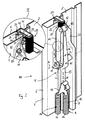
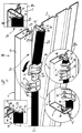
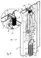
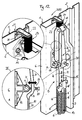
- the swing arm 100, 200, 300 with a protective device 20 provided in the following based on the illustration 1, 2 and 4 to 8 is explained.
- the protection device 20 comprises in the gap area, i.e. in the Area of the gate gap 21 between the frame 1 and the Door leaf 2, sealing or stop strips 22 and 23 and at the second embodiment 200 of the swing gate additionally another cover 60 for the rocker arm mechanism 5.
- They are used for protective covering and sealing of the door leaf gap 21 serving sealing strips 22 and 23 described. They include a stop bar on the frame side or sealing strip 22 and a stop or sealing strip 23 on the door leaf side.
- the frame-side sealing strip 22 is formed by a Profile bar that as a first profile section on the side frame 6 fixed supporting profile web 24, from which a second profile section in the form of a freely ending flange or profile leg 25 protrudes.
- the profile web 24 is for gripping on the frame spar 6 with two fastening sections 26 and 27 provided perpendicular to one of the frame 1 project from the facing side of the profile web 24.
- the first Fastening section 26 is with barb elements 28 provided and for insertion and fixed rest or holding into a face 29 at the end of the door opening (which are usually arranged parallel to the reveal opening is) of the frame 6 existing retaining groove 30 is formed.
- the second fastening section protrudes 27 in such a way from that through the profile web 24 formed first profile section that he the door leaf side Inner edge 32 of the frame spar 6 in particular gripping around.
- a recess 33 is also a 4 and 5 stop block 34 shown, the for guiding the door leaf movement, especially for limiting the same or serves as a stop for the door leaf 2.
- the stop block 34 is in the area of the inner edge 32 in the height at which the initial Swivel axis of the door leaf 2 is located. I.e. When opening from the closed position, the door leaf 2 moves above the upper edge 35 of the stop block in the gate opening in and out of it. For the below this initial pivot axis The edge area of the door leaf 2 serves the sealing strip 22 in Closed state as a sealing stop. For this is the Sealing strip 22 from its beginning at the lower corner 10 of the swing gate up to the bracket on the Stop block 34 with the forming the second profile section Profile leg 25 provided as a sealing lip works. Also the second mounting section 27, the Inner edge 32 is non-gripping, ends at the Stop block 34. In addition, the first profile section, i.e.
- the stop block 34 is on its stop side 36 for receiving the end 37 of the second profile section (the profile leg 25) and the formed by the narrowing paragraph 38 of the first Profile section (of the supporting profile web 24) provided with a recess 39 into which the ends 37, 38 are fitted.
- a definition of the sealing strip on the frame side 22 is also in particular embodiments possible that the second attachment portion 27 and / or the ends 37, 38 by tightening the for mounting the bearing block 11 or the stop block 34 serving screws 40, 41 in the recesses or recesses 33 and 39 can be clamped.
- the sealing strip 22 has in the area between the corner 10 and the stop block 34 due to the load-bearing profile web 24 and the one acting as a sealing lip Profile leg 25 substantially approximately an L-shaped Cross-sectional shape when looking at the mounting sections 26, 27 once out of consideration.
- the main one Profile web 24 is reinforced in the region of the groove 30 executed. For this he is how to look at the different shown cross sections can be seen with a Provide thickening 42. As can be seen from FIGS. 4 and 5, this reinforced area continues at the Groove 30 also beyond the stop block 34 upwards away. Thus, the reinforced area and if necessary the entire first profile section as protection against Traces of grinding or impact or designed as a grinding guide.
- the sealing strip 22 thus serves in the illustrated Embodiment not only for sealing and covering the Gate gap 21, it also replaces the conventional contact strips and performs their function.
- This sealing strip 23 needs, since it is the one shown here Examples do not fulfill an anti-slip function must not necessarily also protrude into the gate gap 21. It therefore points in the example shown in essentially a Z-shaped cross-section, with a central profile web 43, of which on the door leaf side a third mounting section 44 and toward the frame 1 to act as a sealing lip or stop lug freely ending profile leg 45 protrudes.
- the third fastening section 44 engages around the inner edge 46 of the door leaf 2 and is on the to be completed Room facing inside 47 of the edge of the door leaf attached with fasteners 48.
- fastening devices 48 are anyway existing screw connections or the like are used, like a screw 49 of the roller bearing block 50 or that of a door leaf-side stop block 51, the 100, 200, 300 barely in the closed state of the swing gate to lie above the frame-side stop block 34 comes (see detail view IVb of Fig. 4).
- the door leaf side Stop block 51 and the roller bearing block 50 are also on their sides facing the door leaf 2 Provide recesses for receiving the sealing strip 23.
- 300 is the profile leg designed as a sealing lip 45 sealing against the frame 1.
- the sealing strips 22 and 23 have protective functions but another protective function, namely that fingers located in the vicinity of the gate gap 21 or similar foreign bodies before crushing To protect closing the door leaf 2.
- the Sealing lip or stop flag i.e. the profile handle 25 or 45, not rigid but as indicated by the arrows in the Detailed views I of Fig. 1 or Fig. 10 or IVa of 4 indicated, movable from the profile web 24 or 43 from.
- the profile leg 25, 45 is there can be moved sideways out of its rest position, i.e. can be folded away in the examples shown.
- the different functions of the sealing strips 22, 23 are thereby easily accessible that, as it were, as a support or Supporting element for the entire sealing strip 22 acting first profile section, i.e. the profile web 24 or 43, made of a material that has other properties has than that for the one acting as a protective lip element second profile section, i.e. the profile leg 25 or 45, material used.
- first profile section i.e. the profile web 24 or 43
- second profile section i.e. the profile leg 25 or 45
- Particularly suitable material pairs for this are hard and soft rubber or hard and Soft PVC. Let such related materials also extrude together so that the sealing strip 22, 23 can be produced in one operation.
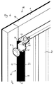
- the cover 60 is as executed essentially U-shaped shell. With a load-bearing profile web 66 and protruding from U-profile leg formed side walls 64 it covers the Storage area and the rear lever arm area of the Swing lever mechanism 5. This is a manual intervention between the lever arm 61 and the spring band 15 largely prevented.
- the cover or cover shell 60 at their edge regions 62 facing the frame 1 similar to those that act as protective or sealing lips Profile legs 25, 45 of the sealing strips 22, 23 in particular compliant to run between the frame 1 and the swiveling lever mechanism to avoid 5 bruises.
- the Compliance of these edge areas 62 of the side walls 64 of the cover 60 is the same as for the sealing strips 22, 23 by selecting a compliant second material ensures that with a more rigid first material in the Composite together forms the cover shell 60.
- the first Material serves metal (sheet steel) or the like, from which a covered or covered by the cover shell 60
- Main body 65 with a substantially U-shaped cross section is formed.
- To form the side walls 64 are U-profile leg of this main body 65 by gluing or spraying or other fastening of protective strips 63 extended from the second material, which Is or comprises soft rubber or soft PVC or the like.
- the supporting profile web 66 of the U main body 65 instructs for attachment to the rear lever arm 61 or the spring band 15 openings 67.
- the cover tray 60 can also be offset Layer are attached so that the cover shell 60 e.g. both as shown on the left side of the swing gate (from can be used on the outside as well as on the right side is.
- a latching device is provided for fastening the cover shell 60 68 provided, which engages on the lever arm bearing 13 first press nipple 69 and one on the spring band 15 attacking second press nipple 70 comprises.
- the first press nipple 69 has for attachment to the Lever arm bearing 13 a preload on the round Crossbar 71 of the lever arm bearing 13 clip-on loop element 72 on.
- the second press nipple 70 engages with its end opposite the cover shell 60 in a first opening 73 provided on the spring band 15 on.
- the spring band 15 itself with a first essentially rectilinear section 74, the free End is connected to the lever arm bearing 13, and one second substantially straight section 75, which as Perforated tape is designed and with a series of eyelets or Holes 76 for one selectable to adjust the tension Engagement of the upper tie rod 18, 18 'is provided, and a step 77 in between.
- stage 77 engages the spring band 15 in the closed position of the swing gate 100, 200, 300 in those shown in FIGS. 2 and 11 Versions around the pivot axis A defining Pivot lever bearing 78 around such that the expansion spring element 14 the swivel lever 7 straight down acted upon.
- the system is in or close to top dead center.
- the rear lever arm 61 is thus with the door leaf closed, neither forwards nor forwards Prestressed behind, it remains in its unstable rest position.
- the weight balance is only when moving the Door leaf 2 properly active from its closed position.
- This setting is for the engine operation of the Swing gates 100, 200, 300 advantageous because the gate so easily by the motor drive in its closed position bring and keep there.
- the door leaf 2 With manual operation, however, it can be very advantageous if the door leaf 2 a certain preload at a slight open state. In this case swings the door leaf 2 after releasing a locking device (not shown) first a little forward its closed position and can then be opened more easily become.
- a selectable setting of such The bias is shown in the Schwenktor shown in Fig. 3 100, 300 by a gate preload adjuster 79 on the spring band 15 allows. Through the gate preload adjuster 79 the spring band 15 in the closed state of the swing gate 100, 300 in one to the rear (into the room to be locked) held inclined position.
- the expansion spring element 14 then not only acts on the spring band 15 straight after below, but also with a small forward-facing one Component over the spring band 15 and the Swivel lever 7 is transferred to the door leaf 2.
- the embodiment shown includes the setting device 79 one into a second one, in particular with a thread Opening 80 on the spring band 15, more precisely on the first Section 74 of the same, engaging adjusting screw 85, their free end at an adjustable depth on the pivot lever bearing Attack 78 of the bearing block 11 can.
- not shown includes the gate preload adjuster 79 on the spring band 15 attachable coasters or the like Level 77 underpinnings. In even more Not shown embodiments, depending on whether Motorized or manual operation is desired, the stepped spring band 15 or a straight or to a lesser extent Spring band inserted.
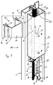
- the transport security device 81 comprises a transport bracket 82, the for the transport of the swing gate 100, 200, 300 the individual Sub-elements 1, 2, 5 and here additionally the the rail 4 folded up to frame 1 holds securely together.
- the transport bracket 81 is designed such that he partially engages around the pivot lever mechanism 5 and partially spreads.
- the swiveling lever mechanism 5 thereby securing and saving space detected in such a way that it is in the closed door leaf 2 appropriate position remains, even in the case in which the pre-assembled in the tensioned state Expansion spring element 14 urges the door leaf 2 to open. Since there are no relative movements of the sub-elements 1, 2, 5, 4 are possible during transport, there is also the risk of Bruises or springback elements unavailable.
- the Schwenktor 100, 200, 300 can without Danger already pre-assembled in all essential parts are delivered so that only a minimal assembly effort is necessary on site.
- the transport bracket 82 encompasses the second, as a perforated belt executed section 75 of the spring band 15 such that the expansion spring element 14 is drawn closer to the frame to save space.
- the expansion spring element 14 outwards, i.e. to the circumference outer side of the frame 6 pulled out so that the Sealing strip 22 is not applied.
- the transport bracket 82 with only a single (releasable) screw 91 and only attached to the frame side 86, which is initially on the outside.
- the transport bracket 82 is with a first angular section 87 led to the inside 31 of the frame 6 and engages under the folded-up running rail 4.
- a second angle section 88 is the Transport bracket 82 then away from the Zargenholm 6 and over the spring band 15 guided, which he clinging to Frame 1 and encompassing the outside.
- the second angular range 82 is in the shape of the various usable tie rod 18 or 18 'adapted.
- a locking lug 92 executed in engage the track guide under pre-tension can, so that the running rail 4 folded up on her Space is kept.
- the running rail 4 is on the upper area of the frame in a not shown Way pivoted and can be opened from the Position over a small start shoulder of the latch 92 are performed in the folded position shown.
- the track is a bit towards the door leaf resiliently biased so that it also in the latch 92 subordinate position remains.
- the Transport bracket with incisions 95 or recesses provided that as a detection device in particular positive locking of the upper tie rod 18 'serve.
- the incisions 95 are arranged such that also other tie rods, e.g. the tie rod 18 of the first Embodiment are detectable. Because the Incisions 95 on the upper and lower edge area are present, the transport bracket 82 is both like shown on the left side frame 6 as also in reverse arrangement on the right side rail usable.
- the transport securing device 81 is not only for the transport of the fully assembled swing gate 100, 200, 300 towards the construction site, but also for internal work Handling in the manufacturing plant interesting.
- the help of the transport bracket can be simple and safe manageable subpackages or assemblies or modules to be pre-assembled, which only in the course of final assembly the Schwenktor 100, 200, 300 are assembled. On this way is the production of a whole series of finished Assemblies possible, which then for very different Gates can be used.
- the side rail 6 already with the swivel lever mechanism 5 and the weight compensation device 8 pre-produced and in stock the transport bracket is kept in a manageable condition.
- the resultant, already with the expected Spring preloaded assemblies can then with frame cross bars of different lengths 93, 94 (see Fig. 1 or 10 or 6) and different widths Gate leaves 2 for swing gates 100 of different widths, 200, 300 can be put together.
- a protective device (20) to cover or seal one between relative to each other movable sub-elements (1, 2) located space (21) suggested the one essentially rigid support or support element (24, 43) and an attached to it arranged protective strip or lip element (25, 45) for covering or sealing the intermediate space (21), that is so flexible or flexible is that there are foreign bodies in the intermediate space (21), especially the fingers or hand of one Person can dodge.
- the protective device at least one sealing strip (22, 23) for the gate gap (21) and / or a cover for a Swing lever mechanism (5) and more preferably consists of one Compound of soft and hard materials.
Abstract
Description
Die Erfindung betrifft eine Schutzvorrichtung für ein insbesondere über Kopf bewegliches Kipp- oder Schwenktor zum schützenden Abdichten und/oder Abdecken eines Zwischen- oder Übergangsbereiches zwischen zwei relativ zueinander beweglichen Teilelementen des Kipp- oder Schwenktores, insbesondere eines Zwischenbereiches zwischen der Zarge und dem Torblatt oder zwischen der Zarge und einem Schwenk- oder Kipphebelwerk. Außerdem betrifft die Erfindung ein eine solche Schutzvorrichtung aufweisendes Kipp- oder Schwenktor, insbesondere ein Einblatt-Überkopftor, umfassend eine Zarge und ein darin schwenk- oder kippbar und insbesondere über Kopf beweglich gehaltenes Torblatt.The invention relates to a protective device for a especially overhead tilting or swinging arm for protective sealing and / or covering an intermediate or transition area between two relative to each other movable sub-elements of the tilt or Swing gates, in particular an intermediate area between the frame and the door leaf or between the frame and a swivel or rocker arm mechanism. Also concerns the invention has such a protective device Tilt or swing gate, in particular a single-leaf overhead door, comprising a frame and a pivoting or tiltable and in particular held overhead Door leaf.
Schutzvorrichtungen der eingangs erwähnten Art gibt es beispielsweise bei bekannten Kipp- oder Schwenktoren in Form einer Schleifleiste, die an den zu dem Torblatt hin gerichteten, insbesondere den zu der Laibung parallel verlaufenden Zargenseiten angebracht sind, um die Bewegung des Torblattes schleifend zu führen oder die Zarge und das Torblatt vor durch die Bewegung des Torblatts verursachten Schleif- oder Stoßspuren zu schützen. Ein weiteres Beispiel für eine bekannte Schutzvorrichtung sind Anschlagleisten, die insbesondere an den Seitenbereichen der Zarge als Anschlag für das Torblatt angeordnet sind und den Torspalt, d.h. den Zwischenbereich zwischen Torblatt und Zarge im Schließzustand des Tores abdecken und somit in gewisser Weise einen Schutz vor Witterungseinflüsse und Eindringen von Schmutz oder dergleichen bieten. In jüngster Zeit wird jedoch nicht nur der Schutz des Tores selbst gegenüber die Qualität beeinträchtigenden Einflüssen oder der durch Abdeckung (und insbesondere durch Isolierung oder Abdichtung) wirkende Schutz gegenüber Witterungseinflüssen groß geschrieben, es wird auch insbesondere im Hinblick auf die Produkthaftung das Erkennen und Vermeiden selbst auch nur bei unsachgemäßer Handhabung auftretender Gefahrenquellen für das Tor benutzende Personen immer wichtiger. Kipp- und Schwenktore sollen also nicht nur vor Wind und Wetter schützen und lange halten, es gilt auch jede von dem Tor ausgehende Gefahr für sich in deren Nähe aufhaltende Personen zu vermeiden.There are protective devices of the type mentioned at the beginning for example in the case of known tilting or swinging gates Shape of a contact strip that goes to the door leaf directed, especially those parallel to the reveal Trending frame sides are attached to the movement of the door leaf or the frame and the door leaf in front by the movement of the door leaf to protect caused grinding or impact marks. On another example of a known protective device are stop bars, especially on the side areas the frame is arranged as a stop for the door leaf and the gate gap, i.e. the intermediate area between Cover the door leaf and frame when the door is closed and thus to some extent protection against the weather and ingress of dirt or the like Offer. In recent times, however, not only that Protection of the gate itself against the quality impairing Influences or by cover (and especially by insulation or sealing) Protection against weather influences is very important, it will also be particularly with regard to product liability recognizing and avoiding even when improper Handling occurring sources of danger for people using the gate are becoming increasingly important. Tilting and Swing gates should not only be used in wind and weather Protect and hold for a long time, each of the gates also applies outgoing danger for people in the vicinity to avoid.
Aufgabe der Erfindung ist es, eine Schutzvorrichtung der eingangs genannten Art zu schaffen, die die durch den Betrieb des Tores ausgehende Gefährdung verringert. Weiterhin soll ein sichereres Kipp- oder Schwenktor geschaffen werden.The object of the invention is to provide a protective device to create the kind mentioned by the operation the danger of the gate is reduced. Farther should create a safer tilting or swinging arm become.
Zum Lösen dieser Aufgabe ist eine Schutzvorrichtung der eingangs genannten Art gekennzeichnet durch wenigstens ein vorzugsweise aus einem ersten, starren, unnachgiebigen und/oder stoßunempfindlichen Material bestehendes Trag- oder Stützelement, das zum Festlegen der Schutzvorrichtung oder eines Teils derselben an einem der beiden Teilelemente befestigbar oder - eventuell auch einstückig damit ausgeführt - mit demselben verbunden ist, und durch wenigstens ein Schutzleisten- oder -lippenelement, das derart an dem Trag- oder Stützelement oder einem von mehreren Trag- oder Stützelementen angebracht und relativ zu dem Trag- oder Stützelement derart beweglich oder nachgiebig ausgeführt ist, daß es einem sich im Übergangs- oder Zwischenbereich befindlichen Fremdkörper, insbesondere einer Hand oder eines Fingers einer Person, im Zuge eines sich aufeinander zu Bewegens der Teilelemente ausweichen kann, um ein Verklemmen oder Quetschen des Fremdkörpers zu verringern oder zu verhindern.To solve this problem, a protective device is the initially mentioned type characterized by at least one preferably from a first, rigid, unyielding and / or existing shock-insensitive material Support or support element that is used to fix the protective device or a part of it on one of the two Partial elements can be attached or - possibly in one piece executed with it - connected to it, and through at least one protective strip or lip element, the such on the support or support element or one of several Support or support elements attached and relative to the support or support element so movable or resilient is that one is in transition or Foreign bodies located in between, in particular a hand or a finger of a person, in the course one to move towards each other to move the sub-elements can cause jamming or crushing of the foreign body to decrease or prevent.
Die Schutzvorrichtung weist also einen starreren Teil, das Trag- oder Stützelement, auf, mit welchem sie an der Zarge, dem Torblatt oder einem sonstigen insbesondere beweglichen Teilelement des Tores, wie z.B. dem Kipp- oder Schwenkhebelwerk, befestigt ist und das noch weitere Funktionen wie zum Beispiel eine Abdeckung zum Schutz vor mechanischer Beanspruchung oder Eingriffen, insbesondere durch Finger oder dergleichen, erfüllen kann. Neben diesem starreren Teil umfaßt die Schutzvorrichtung einen nachgiebigen Teil in Form eines abragenden Schutzlippen- oder -leistenelements, das insbesondere Dichtfunktionen, aber auch zusätzlich oder alternativ abdeckende Funktionen zum Schutz vor Eingriffen erfüllen kann. Die Nachgiebigkeit wird durch eine bewegliche Aufhängung oder vorzugsweise durch Auswahl eines weicheren oder elastischeren Materials gewährleistet. Dabei ist darauf zu achten, daß das Schutzleisten- oder Schutzlippenelement Fremdkörpern, die sich im Zwischenraum zwischen den relativ zueinander beweglichen Teilelementen befinden, ausweichen kann. Befindet sich also ein Finger einer Person z.B. im abzudichtenden oder abzudeckenden Zwischenbereich, so wird im Zuge des aufeinander zu Bewegens der Teilelemente zunächst das Schutzlippen- oder -leistenelement den Finger erfassen, diesen aber nicht einquetschen, sondern aufgrund seiner Nachgiebigkeit ausweichen. Dadurch lassen sich Verletzungen von sich im Schwenk- oder Kippbereich des Tores aufhaltenden Personen vermeiden, und Quetschgefahren lassen sich entschärfen.The protective device therefore has a more rigid part, the support or support element, with which they are attached to the Frame, the door leaf or any other particularly movable Partial element of the gate, e.g. the tipping or Swing lever mechanism, is attached and the other Features such as a cover to protect against mechanical stress or interference, in particular by fingers or the like. Besides this more rigid part, the protective device includes a compliant part in the form of a protruding lip or -strip element, which in particular sealing functions, but also additional or alternative covering functions to protect against interference. The compliance is by a movable suspension or preferably by choosing a softer or more elastic Material guaranteed. It is important to ensure that the protective strip or protective lip element foreign bodies, which are in the space between the relative to each other movable sub-elements can. So is a person's finger e.g. in the intermediate area to be sealed or covered, so becomes in the course of moving the partial elements towards each other first the protective lip or strip element the finger capture, but not squeeze it, but dodge due to its compliance. Let it through injuries in the swivel or tilt area Avoid people stopping the gate and risk of crushing can be defused.
Vorteilhafte Ausgestaltungen der Erfindung sind Gegenstand der Unteransprüche.Advantageous embodiments of the invention are the subject of subclaims.
Besonders vorteilhaft ist eine Ausführung, bei der die Schutzvorrichtung einen Materialmix aufweist, sozusagen aus zwei Komponenten besteht. Demgemäß besteht bei einer bevorzugten Ausgestaltung der Erfindung das Trag- oder Stützelement aus einem ersten, dem starreren Material, während das daran angebrachte Schutzlippen- oder - leistenelement aus einem zweiten Material besteht oder ein solches zum Sicherstellen seiner Nachgiebigkeit aufweist. Das zweite Material ist dabei nachgiebiger als das erste Material ausgeführt, also insbesondere elastischer oder weicher. Besonders vorteilhaft ist dabei, wenn artverwandte Materialien wie zum Beispiel Hart- und Weichgummi (Hartgummi und Gummi) oder Hart- und Weich-PVC oder dergleichen mehr verwendet werden, die sich gemeinsam herstellen oder verarbeiten lassen, also zum Beispiel gemeinsam extrudieren lassen. Andererseits sind aber auch viele weitere Materialverbünde denkbar. Zum Beispiel könnte für das Trag- oder Stützelement Metall verwendet werden, an das (Weich-)Gummilippen oder (Weich-)PVC-Leisten oder dergleichen angeklebt, angespritzt oder sonstwie abragend befestigt werden.An embodiment in which the Protection device has a material mix, so to speak consists of two components. Accordingly, there is one preferred embodiment of the invention, the support or Support element made of a first, the more rigid material, while the attached protective lip or strip element consists of a second material or a has such to ensure its compliance. The second material is more flexible than the first Made of material, in particular elastic or softer. It is particularly advantageous if related Materials such as hard and soft rubber (Hard rubber and rubber) or hard and soft PVC or the like more are used that are made together or have it processed, for example together let extrude. On the other hand, too many other material combinations possible. For example could use metal for the support or support element the (soft) rubber lips or (soft) PVC strips or the like glued, injection molded or otherwise be attached protruding.
Die Erfindung ist im wesentlichen für zwei Einsatzzwecke am Tor besonders vorteilhaft: einerseits zum Abdecken oder Abdichten des Torspalts zwischen Zarge und Torblatt oder andererseits zum Abdecken eines Schwenkhebelwerks, wobei in beiden Fällen ein Fingereingriff, wenn nicht gar vermieden, so doch ungefährlicher (für dennoch eingreifende Finger) gemacht werden soll.The invention is essentially for two purposes Particularly advantageous at the gate: on the one hand for covering or sealing the door gap between the frame and the door leaf or on the other hand to cover a pivot lever mechanism, in both cases a finger intervention, if not at all avoided, but still less dangerous (for nonetheless intervening Fingers) should be made.
Demgemäß gibt es zwei besonders bevorzugte Grundausführungsformen der Erfindung. Eine erste grundsätzliche Ausgestaltung ist in Form einer oder mehrerer Dichtleisten insbesondere anstelle oder zusätzlich zu der oder den üblichen, an Zargenseitenholmen oder seitlichen Torblattberandungen vorhandenen Schleifleiste(n) vorgesehen, wobei in einer besonders vorteilhaften Ausgestaltung der Erfindung das Trag- oder Stützelement die Funktion der Schleifleiste mit erfüllt. Eine zweite grundsätzliche Ausgestaltung ist als Abdeckkappe oder Abdeckschale für das Schwenkhebelwerk ausgeführt, dort insbesondere für den Bereich, an dem die Gewichtsausgleichfeder angreift und der sich im Zuge der Torblattschließbewegung der Zarge nähert. Selbstverständlich ist aber auch eine Schutzvorrichtung denkbar, die sowohl die erfindungsgemäße(n) Dichtleiste(n) als auch eine oder mehrere erfindungsgemäße Abdeckschalen oder -kappen als einzelne Teilelemente umfaßt und somit die Vorteile der beiden grundsätzlichen Ausgestaltungen miteinander verbindet.Accordingly, there are two particularly preferred basic embodiments the invention. A first basic design is in the form of one or more sealing strips in particular instead of or in addition to the usual one or more on frame side rails or side door leaf edges existing contact strip (s) provided, whereby in a particularly advantageous embodiment of the Invention the support or support element the function of Contact strip with met. A second basic Design is as a cover or cover for executed the swing lever mechanism, there especially for the area where the counterbalance spring engages and which in the course of the door leaf closing movement of the Frame approaches. Of course, there is also one Protective device conceivable, which both the invention (s) Sealing strip (s) as well as one or more according to the invention Cover shells or caps as individual sub-elements includes and thus the advantages of the two basic ones Designs connects together.
Die erste Grundausführungsform der Erfindung, die erfindungsgemäße Dichtleiste, ist in bevorzugter Ausgestaltung als Profilleiste ausgebildet, beispielsweise im wesentlichen mit L- oder Z-förmigen Querschnitt. Dabei bildet eine erster Profilabschnitt davon, beispielsweise der Hauptsteg des L-förmigen Querschnitts, das Trag- oder Stützelement, wobei ein davon abragender zweiter Profilabschnitt das Schutzlippenelement bildet. Der zweite Profilabschnitt, der beim Beispiel des L-förmigen Querschnitts durch den kurzen Schenkel gebildet sein kann, ist insbesondere als Dichtlippe oder Anschlagfahne für das jeweils andere Teilelement ausgeführt, wobei die Dichtlippe oder Anschlagfahne vorzugsweise aus derart nachgiebigem Material besteht, daß sie einem Finger, anstatt ihn einzuquetschen, ausweicht, also z.B. ihn weich umschließt. Neben der Schutzfunktion für sich im Zwischenbereich befindliche Finger (oder einer ganzen Hand oder auch eines anderen Fremdkörpers) hat das Schutzlippenelement in seiner Ausbildung als Dichtlippe naturgemäß auch Dichtfunktionen, d.h. es überdeckt abdichtend den Zwischenraum oder greift abdichtend in diesen ein. Auch wegen seiner Dichtwirkungen ist das bevorzugte verwendete nachgiebige zweite Material der Zweikomponentendichtleiste vorteilhaft, so daß die Dichtlippe auch für Einsatzzwecke geeignet ist, in der sie keine Fingerschutzfunktion erfüllt. Im Prinzip muß dabei, wenngleich dies bevorzugt ist, nicht der gesamte zweite Profilabschnitt aus dem weicheren Material bestehen. Es ist z.B. für den Fingerschutz auch ausreichend, wenn ein Endbereich oder ein Verbindungsbereich aus solchem Material besteht, solange dadurch ein Ausweichen des Schutzlippenelements bei Fingereingriff oder dergleichen gewährleistet werden kann.The first basic embodiment of the invention, the invention Sealing strip is in a preferred embodiment formed as a profile strip, for example essentially with L or Z-shaped cross section. Thereby forms a first profile section thereof, for example the Main web of the L-shaped cross section, the supporting or Support element, wherein a second profile section protruding therefrom forms the protective lip element. The second Profile section, which in the example of the L-shaped cross section can be formed by the short leg, is particularly suitable as a sealing lip or stop flag for executed the other sub-element, the Sealing lip or stop lug preferably from such Compliant material is that instead of a finger squeezing it, evades, e.g. him soft encloses. In addition to the protective function for itself in the intermediate area fingers (or an entire hand or another foreign body) has the protective lip element naturally in his training as a sealing lip also sealing functions, i.e. it covers the Intermediate space or sealingly engages in this. Also because of its sealing effects, the preferred one is used compliant second material of the two-component sealing strip advantageous so that the sealing lip can also be used is suitable in which it has no finger protection function Fulfills. In principle, although this is preferred is not the entire second profile section consist of the softer material. It is e.g. for finger protection also sufficient if an end range or a Connection area consists of such material, as long as thereby evading the protective lip element upon finger intervention or the like can be guaranteed.
Der erste Profilabschnitt, der das Trag- oder Stützelement bildet, kann zur Befestigung der Dichtleiste an der Zarge oder dem Torblatt verschieden ausgeführt sein. Vorteilhafterweise umfaßt er ein insbesondere leistenförmig gerades, tragendes Stück also z.B. den breiten Profilsteg einer im wesentlichen L-förmigen Dichtleiste, von dem außer dem Schutzlippenelement auch ein Befestigungsabschnitt abragt, mit Hilfe dessen die Befestigung der Dichtleiste an Torblatt bzw. Zarge durchführbar ist.The first profile section, which is the support or support element forms, can be used to attach the sealing strip to the Frame or door leaf can be designed differently. Advantageously it includes a particularly strip-shaped straight, load-bearing piece, e.g. the wide profile web an essentially L-shaped sealing strip, of which except the protective lip element also a fastening section protrudes, with the help of which the attachment of the Sealing strip can be carried out on the door leaf or frame.
Bei einer weiter vorteilhaften Ausgestaltung werden dabei die zum Anbringen von Schleifleisten an der Zarge üblichen Haltenuten verwendet, wobei dann der Befestigungsabschnitt zum Eingreifen in eine solche, üblicherweise an der zur Laibung parallelen, dem Torblatt zugewandten Zargenstirnseite vorhandene Nut ausgebildet ist. Andererseits können an der Zarge oder dem Torblatt auch an anderen Stellen Haltenuten zum Befestigen der erfindungsgemäßen Dichtleiste vorgesehen werden, also z.B. an der in das Innere des zu verschließenden Raumes weisenden Zargenseite, wobei dann der Befestigungsabschnitt entsprechend ausgebildet ist.In a further advantageous embodiment the usual for attaching sanding strips to the frame Holding grooves used, then the fastening section to intervene in such, usually at the frame face parallel to the reveal and facing the door leaf existing groove is formed. On the other hand can be on the frame or the door leaf on others Place retaining grooves for attaching the invention Sealing strips are provided, e.g. at the in the inside of the frame side facing the locked room, then the fastening section accordingly is trained.
Zusätzlich oder anstelle eines zum (insbesondere rastenden oder verklemmenden) Eingriff in Haltenuten ausgebildeten Befestigungsabschnitt kann auch ein anderer oder weiterer Befestigungsabschnitt vorgesehen sein, der sich an einer Kante des Torteilelementes, an dem die Dichtleiste zu befestigen ist, abstützt oder diese umgreift. Der umgreifende Befestigungsabschnitt kann insbesondere länger ausgeführt sein und mit Schrauben oder dergleichen Befestigungseinrichtungen an der Zarge bzw. dem Torblatt festgelegt werden, wobei dann der Nuteneingriff auch ganz entfallen kann. Die gesamte Dichtleiste kann dabei Z-förmig ausgestaltet sein, wobei vorzugsweise die Dicht- oder Anschlaglippe an dem einem Ende und ein Befestigungsabschnitt an dem anderen Ende des tragenden Mittelstücks in verschiedene Richtungen abragen.In addition to or instead of one for (especially resting or jamming) trained in holding grooves Fastening section can be another or further fastening section may be provided, which itself on an edge of the gate element, on which the sealing strip is to be attached, supported or embraced. The encompassing fastening section can in particular be longer be executed and with screws or the like Fastening devices on the frame or door leaf be determined, the groove engagement then also entirely can be omitted. The entire sealing strip can be Z-shaped be designed, preferably the sealing or Stop lip at one end and a fastening section at the other end of the load-bearing center piece in protrude different directions.
Der umgreifende freie Endbereich des Befestigungsabschnitts kann also nochmals zusätzlich festgelegt sein. So sind Verschraubungen, Verklebungen, Nieten und der gleichen mehr denkbar. In weiter bevorzugter Ausgestaltung sind von dem Torteilelement, an dem die Dichtleiste zu befestigen ist, abragende Einrichtungen wie Lagerböcke, Laufschienenhalterungen, Rollenlager oder sonstige Lagerungen oder Führungen für das Torblatt, das Schwenk- oder Kipphebelwerk, das Gewichtsausgleichsfederelement oder dergleichen, jeweils mit einer Ausnehmung oder Aussparung versehen, in die das freie Ende des umgreifenden Befestigungsabschnitts eingeführt und eventuell auch darin verklemmt werden kann.The encompassing free end area of the fastening section can also be specified again. So are screw connections, bonds, rivets and the same more conceivable. In a further preferred embodiment are from the gate part element on which the sealing strip to be attached, protruding devices such as pillow blocks, Track holders, roller bearings or other Bearings or guides for the door leaf, the swivel or Rocker arm mechanism, the weight compensation spring element or the like, each with a recess or recess provided in which the free end of the encompassing Fastening section introduced and possibly also can get stuck in it.
Bei der der zweiten Grundausführungsform der Erfindung, bei der die Schutzvorrichtung eine Abdeckung für die zumindest teilweise Abdeckung des Schwenk- oder Kipphebelwerkes umfaßt, ist diese bevorzugt direkt auf dem Schwenk- oder Kipphebel oder damit zur gemeinsamen Bewegung verbundener Teile befestigbar. Die vorzugsweise in Form einer Kappe oder Schale vorliegende Abdeckung umfaßt weiter bevorzugt einen Trag- oder Hauptkörper aus Metall oder dergleichem widerstandsfähigen ersten Material. Auch der Hauptkörper weist in bevorzugter Ausführung eine profilierte Form auf, die je nach Schutzfunktion verschiedener Gestalt sein kann. Ein sehr guter weil umgreifender Schutz wird durch eine U-förmige Querschnittsform mit einem geraden Profilsteg und zwei davon abragenden Profilschenkeln erreicht.In the second basic embodiment of the invention, in which the protective device a cover for the at least partial coverage of the swivel or rocker arm mechanism includes, this is preferably directly on the Swivel or rocker arm or thus for joint movement connected parts attachable. The preferably in Cover form in the form of a cap or shell more preferably a support or main body made of metal or the like tough first material. Also the main body has a profiled in a preferred embodiment Form on, which varies depending on the protective function Shape can be. A very good one because it is comprehensive Protection is provided by a U-shaped cross-sectional shape with a straight profile web and two profile legs protruding from it reached.
Die Endbereiche der Schenkel oder sonstiger insbesondere auf die Zarge hin weisender Kantenbereiche der Abdeckung sind bevorzugt als die erfindungsgemäßen Schutzleistenelemente ausgebildet, d.h. derart nachgiebig gehalten, daß ein sich im Nahbereich der Zarge befindlicher Finger oder Handbereich vor Verletzung durch diese Kantenbereiche geschützt wird. Sie bestehen insbesondere aus (Weich-)Gummi oder (Weich-)PVC oder dergleichen.The end regions of the legs or other in particular edge areas of the cover pointing towards the frame are preferred as the protective strip elements according to the invention trained, i.e. so resilient that a located in the vicinity of the frame Finger or hand area from injury from these edge areas is protected. In particular, they consist of (Soft) rubber or (soft) PVC or the like.
In weiter bevorzugter Ausführung wird die Abdeckung an einem Ende eines Schwenkhebels oder einem dort vorhandenen Hebelarmlagers und/oder einem daran angreifenden Federband befestigt. Ein solches Federband dient dazu, den Schwenkhebel mit einem zum Gewichtsausgleich vorhandenen Dehnungsfederelement, also z.B. einer Schraubenzugfeder oder einem Federpaket, insbesondere einstellbar zu verbinden. Zur Befestigung der Abdeckung ist eine an dem (hinteren, kurzen) Hebelende, dem Hebelarmlager und/oder dem Federband vorhandene oder anbringbare Befestigungseinrichtung zur form- oder reibschlüssigen Befestigung der Abdeckung an dem Hebelwerk vorgesehen. Die Befestigungseinrichtung umfaßt vorzugsweise Rast- oder Klemmelemente oder Aufdrücknippel. Dabei ist das mit dem Hebelende zu verbindende Rast- oder Klemmelement oder der mit dem Hebelende zu verbindende Aufdrücknippel weiter bevorzugt mit einem Schlaufen- oder Greifelement versehen, das auf einen Quersteg oder dergleichen an dem Hebelarm, an welchem das Federband angreift, oder an dem zum Angriff für die Gewichtsausgleicheinrichtung dienende Hebelarmlager unter Vorspannung aufklipsbar ist. Ist dann noch ein zweiter Aufdrücknippel oder dergleichen an dem Federband vorhanden, so kann zunächst die Abdeckung an dem Hebelende auf das Hebelarmlager aufgeklipst werden, dann durch Verschwenken um dieses Hebelarmlager in die endgültige Befestigungsposition gebracht werden und dort durch Aufklipsen (Verklemmen, Verrasten,...) an dem an dem Federband vorhanden Aufdrücknippel oder dergleichen festgelegt werden.In a further preferred embodiment, the cover is on one end of a pivot lever or one existing there Lever arm bearing and / or a spring band acting on it attached. Such a spring band is used to Swivel lever with an existing one for weight compensation Expansion spring element, e.g. a coil spring or a spring assembly, in particular adjustable to connect. To attach the cover is one on the (rear, short) lever end, the lever arm bearing and / or the spring band existing or attachable fastening device for positive or frictional fastening the cover provided on the lever mechanism. The fastener preferably includes locking or clamping elements or press nipple. This is the end of the lever locking or clamping element to be connected or with the press-on nipple to be connected to the lever end is further preferred provided with a loop or gripping element that on a crossbar or the like on the lever arm which the spring band attacks, or on which to attack lever arm bearings for the weight balancing device can be clipped on under tension. Then is still one second press nipple or the like on the spring band available, so the cover at the end of the lever be clipped onto the lever arm bearing, then by Swiveling around this lever arm bearing into the final one Attachment position are brought and there by clipping (Jamming, locking, ...) on the on the spring band existing press nipple or the like set become.
Ausführungsbeispiele der Erfindung werden nachstehend anhand der beigefügten Zeichnung näher erläutert. Darin zeigt:
- Fig. 1
- eine teilweise weggeschnittene perspektivische Innen- oder Rückansicht eines Bereichs einer unteren Ecke eines einblattigen Überkopf-Schwenktores für eine Garage oder dergleichen in einer ersten Ausführungsform sowie einen vergrößerten Detailausschnitt davon,
- Fig. 2
- eine teilweise weggeschnittene perspektivische Innen- oder Rückansicht eines oberhalb der Ecke von Fig. 1 gelegenen Seitenbereichs des Schwenktores von Fig. 1 sowie eine vergrößerte Detailansicht eines darin umkreisten Detailbereichs,
- Fig. 3
- eine Ansicht vergleichbar mit der von Fig. 2, wobei das Schwenktor zusätzlich mit einer Torvorspannungseinstelleinrichtung versehen ist, mit einer Detailansicht dieser Einrichtung,
- Fig. 4
- eine teilweise weggeschnittene perspektivische Innen- oder Rückansicht eines oberhalb des in den Fig. 2 oder 3 gezeigten Seitenbereiches gelegenen weiteren Seitenbereichs des Schwenktores mit vier Detailansichten,
- Fig. 5
- teilweise weggeschnittene perspektivische Ansicht von vorne (außen) auf den in Fig. 4 gezeigten Bereich eines Zargenholms des Schwenktores,
- Fig. 6
- eine teilweise weggeschnittene perspektivische Innen- oder Rückansicht auf eine obere Ecke des Schwenktores,
- Fig. 7
- eine der Darstellung in Fig. 2 vergleichbare Ansicht eines Schwenktores in einer zweiten Ausführungsform bei geschlossenem Torblatt mit einer Detailansicht,
- Fig. 8
- eine Darstellung ähnlich wie in Fig. 7, jedoch mit leicht geöffnetem Torblatt und ohne Detailansicht,
- Fig. 9
- eine teilweise weggeschnittene perspektivische Rückansicht auf den auch in Fig. 2 gezeigten Seitenbereich des Schwenktores von Fig. 2 in einem vormontierten, für den Transport vom Hersteller zur Baustelle zusammengelegten Zustand, und die
- Fig. 10
bis 13 - mit den Darstellungen in den Fig. 1, 2, 3 bzw. 9 vergleichbare Ansichten eines Schwenktores in einer dritten Ausführungsform.
- Fig. 1
- 2 shows a partially cut-away perspective interior or rear view of a region of a lower corner of a single-leaf overhead swing gate for a garage or the like in a first embodiment and an enlarged detail section thereof,
- Fig. 2
- 2 shows a partially cut-away perspective interior or rear view of a side area of the swing gate of FIG. 1 located above the corner of FIG. 1 and an enlarged detail view of a detail area encircled therein,
- Fig. 3
- 2 shows a view comparable to that of FIG. 2, the swing arm being additionally provided with a gate preload setting device, with a detailed view of this device,
- Fig. 4
- 3 shows a partially cut away perspective interior or rear view of a further side area of the swing gate located above the side area shown in FIGS. 2 or 3, with four detailed views,
- Fig. 5
- partly cut away perspective view from the front (outside) of the area of a frame spar of the swing gate shown in FIG. 4,
- Fig. 6
- a partially cut-away perspective interior or rear view of an upper corner of the swing gate,
- Fig. 7
- 2 shows a view of a swing gate comparable to the representation in FIG. 2 in a second embodiment with the door leaf closed, with a detailed view,
- Fig. 8
- 7 shows a representation similar to that in FIG. 7, but with the door leaf slightly open and without a detailed view,
- Fig. 9
- 3 shows a partially cut-away perspective rear view of the side region of the swing gate of FIG. 2, also shown in FIG. 2, in a preassembled state, folded up for transport from the manufacturer to the construction site, and FIG
- 10 to 13
- with the representations in FIGS. 1, 2, 3 and 9 comparable views of a swing gate in a third embodiment.
In den Fig. sind jeweils Teilbereiche oder Teilelemente
von Schwenktoren 100, 200, 300 für Garagen dargestellt.
Die dargestellten Schwenktore 100, 200, 300 weisen jeweils
eine Zarge 1 und ein über Kopf bewegbares Torblatt
2 auf. Das Torblatt 2 ist im eingebauten Zustand am oberen
Bereich über Rollen 3 (Fig. 6) in an der Decke oder
dergleichen der Garage in horizontaler Richtung in nicht
dargestellter aber hinlänglich bekannter Weise befestigten
Laufschienen 4 geführt. Zum Öffnen schwenkt das Torblatt
2 derart auf, daß es mit seiner unteren Kante 2a
einen aus der Toröffnung nach außen reichenden Bogen beschreibt,
bis es in seine im wesentlichen durch die Laufschienen
4 definierte weitgehend horizontale Öffnungslage
gelangt. Diese Schwenkbewegung über Kopf nach oben wird
durch ein Schwenkhebelwerk 5 geführt, das an jedem Seitenbereich
des Schwenktores 100, 200, 300 einen an dem
jeweiligen seitlichen Zargenholm 6 gelagerten Schwenkhebel
7 und eine Gewichtsausgleichseinrichtung 8 umfaßt. In the figures there are partial areas or partial elements
represented by
Der Schwenkhebel 7 greift mit seinen einem Ende 9 an der
unteren Ecke 10 des Torblatts 2 an (siehe z.B. Fig. 1).
Der Schwenkhebel 7 ist an einem Lagerbock 11 zum Schwenken
um eine Schwenkachse A gelagert (Fig. 2). An dem anderen
Ende 12 des Schwenkhebels 7 ist ein Hebelarmlager
13 vorgesehen, an dem die Gewichtsausgleicheinrichtung 8
zum Ausgleichen des Torblattgewichts angreift.The
Die Gewichtsausgleichseinrichtung 8 weist ein Dehnungsfederelement
14, und ein Federband 15 zum einstellbaren Befestigen
des Dehnungsfederelements 14 an dem Ende 12 des
Schwenkhebels 7 auf. Das Dehnungsfederelement 14 wird bei
den dargestellten Ausführungen durch ein Federpaket gebildet
und weist mehrere parallel angreifende Schraubenzugfedern
16, 16' auf, die über Zuganker 17, 17' und 18,
18' gemeinsam an der Zarge 1 (siehe Fig. 1, 10) bzw. dem
Federband 15 (z.B. Fig. 2, 11) befestigt sind. Die erste,
in den Fig. 1 bis 6 gezeigte und die dritte, in den Fig.
10 bis 13 gezeigte Ausführungsform 100, 300 des Schwenktores
unterscheiden sich im wesentlichen nur durch die
Anzahl und Art ihrer Schraubenzugfedern 16, 16' und durch
ihre jeweils angepaßten Zuganker 17, 18 bzw. 17', 18'.The
Die einzelnen Teilelemente 1, 2 und 5 des Schwenktores
100, 200, 300, also die Zarge 1, das Torblatt 2 und das
Schwenkhebelwerk 5, bewegen sich im Zuge der Öffnungs- und
Schließbewegung relativ zueinander. Um die einzelnen
Teilelemente 1, 2 und 5 vor aus dieser Relativbewegung
resultierenden mechanischen Beanspruchung aufgrund Aneinderschleifens
oder -stoßen oder dergleichen zu schützen,
und/oder zum schützenden Abdichten und Abdecken von Zwischenbereichen
zwischen diesen Teilelementen 1, 2 und 5
ist das Schwenktor 100, 200, 300 mit einer Schutzvorrichtung
20 versehen, die im folgenden anhand der Darstellung
in den Fig. 1, 2 und 4 bis 8 erläutert wird.The
Die Schutzvorrichtung 20 umfaßt im Spaltbereich, d.h. im
Bereich des Torspaltes 21 zwischen der Zarge 1 und dem
Torblatt 2, Dicht- oder Anschlagleisten 22 und 23 und bei
der zweiten Ausführungsform 200 des Schwenktores zusätzlich
noch eine Abdeckung 60 für das Schwenkhebelwerk 5.The
Zunächst werden die zum schützenden Abdecken und Abdichten
des Torblattspaltes 21 dienenden Dichtleisten 22 und
23 beschrieben. Sie umfassen eine zargenseitige Anschlagleiste
oder Dichtleiste 22 und eine torblattseitige Anschlag- oder Dichtleiste 23.First, they are used for protective covering and sealing
of the
Die zargenseitige Dichtleiste 22 ist gebildet durch eine
Profilleiste, die als einen ersten Profilabschnitt einen
an dem seitlichen Zargenholm 6 befestigten tragenden Profilsteg
24 aufweist, von dem aus ein zweiter Profilabschnitt
in Form eines frei endenden Flansches oder Profilschenkels
25 abragt. Der Profilsteg 24 ist zum Angreifen
an dem Zargenholm 6 mit zwei Befestigungsabschnitten
26 und 27 versehen, die senkrecht von einer der Zarge 1
zugewandten Seite des Profilsteges 24 abragen. Der erste
Befestigungsabschnitt 26 ist mit Widerhakenelementen 28
versehen und zum Einführen und Festrasten oder Festhalten
in eine an der die Toröffnung berandenden Stirnseite 29
(die üblicherweise parallel zur Laibungsöffnung angeordnet
wird) des Zargenholmes 6 vorhandene Haltenut 30 gebildet.
Bei einigen Torblättern bekannter Art dienen solche
Nuten 30 dazu, Schleifleisten festzuhalten, die zum
Schutz vor Schleifschäden durch Aneinanderschleifen der
Zarge 1 und des Torblatt 2 an den dem Torblatt 2 zugewandten
Seiten 29 der Zargenholme 6 angebracht sind. Bei
einer nicht dargestellten Ausführungsform ist zusätzlich
oder anstatt der Nut 30 eine Haltenut an der dem zu verschließenden
Raum zugewandten Innenseite 31 des Zargenholms
6 angeordnet, in welche Nut ein entsprechender
Fortsatz an dem Befestigungsabschnitt 27 eingreift.The frame-
Bei der dargestellten Ausführung ragt der zweite Befestigungsabschnitt
27 derart von dem durch den Profilsteg 24
gebildeten ersten Profilabschnitt ab, daß er die torblattseitige
Innenkante 32 des Zargenholms 6 insbesondere
klemmend umgreift. Wie aus der eingekreisten Detaildarstellung
II von Fig. 2 ersichtlich, ist der Lagerbock 11
an seiner dem Torblatt 2 zugewandten Seite zum Aufnehmen
dieses Befestigungsabschnittes 27 mit einer Aussparung 33
versehen. Mit einer solchen Aussparung 33 ist auch ein
den Fig. 4 und 5 gezeigter Anschlagblock 34 versehen, der
zum Führen der Torblattbewegung, insbesondere zum Begrenzen
derselben oder als Anschlag für das Torblatt 2 dient.In the embodiment shown, the second fastening section protrudes
27 in such a way from that through the
Der Anschlagblock 34 ist im Bereich der Innenkante 32 in
derjenigen Höhe angeordnet, in der sich die anfängliche
Schwenkachse des Torblatts 2 befindet. D.h. beim Öffnen
aus der Schließlage bewegt sich das Torblatt 2 oberhalb
der Oberkante 35 des Anschlagblockes in die Toröffnung
hinein und unterhalb derselben aus dieser hinaus. Für den
unterhalb dieser anfänglichen Schwenkachse liegenden
Randbereich des Torblattes 2 dient die Dichtleiste 22 im
Schließzustand als dichtender Anschlag. Hierzu ist die
Dichtleiste 22 von ihrem Anfang an der unteren Ecke 10
des Schwenktores ausgehend bis zu der Halterung an dem
Anschlagblock 34 mit dem den zweiten Profilabschnitt bildenden
Profilschenkel 25 versehen, der als Dichtlippe
wirkt. Auch der zweite Befestigungsabschnitt 27, der die
Innenkante 32 ungreifend ausgebildet ist, endet an dem
Anschlagblock 34. Außerdem wird auch der erste Profilabschnitt,
d.h. der Profilsteg 24, der zargenseitigen
Dichtleiste 22 im Bereich des Anschlagblockes 34 wie
hiernach noch näher erläutert viel schmäler. Wie aus Fig.
5 ersichtlich, ist der Anschlagblock 34 an seiner Anschlagseite
36 zur Aufnahme des Endes 37 des zweiten Profilabschnittes
(des Profilschenkels 25) als auch des
durch die Verschmälerung gebildeten Absatzes 38 des ersten
Profilabschnittes (des tragenden Profilsteges 24)
mit einer Ausnehmung 39 versehen, in die die Enden 37, 38
eingepaßt sind. Eine Festlegung der zargenseitigen Dichtleiste
22 ist darüber hinaus in besonderen Ausführungsformen
dadurch möglich, daß der zweite Befestigungsabschnitt
27 und/oder die Enden 37, 38 über Festziehen der
zur Befestigung des Lagerbockes 11 oder des Anschlagblockes
34 dienenden Schrauben 40, 41 in den Aussparungen
oder Ausnehmungen 33 bzw. 39 festklemmbar sind.The
Insgesamt weist die Dichtleiste 22 in dem Bereich zwischen
der Ecke 10 und dem Anschlagblock 34 aufgrund des
tragenden Profilstegs 24 und des als Dichtlippe fungierenden
Profilschenkels 25 im wesentlichen etwa eine L-förmige
Querschnittsform auf, wenn man die Befestigungsabschnitte
26, 27 einmal außer Betracht läßt. Der tragende
Profilsteg 24 ist dabei im Bereich der Nut 30 verstärkt
ausgeführt. Hierzu ist er, wie man an den verschiedenen
gezeigten Querschnitten erkennen kann, mit einer
Verdickung 42 versehen. Wie aus den Fig. 4 und 5 ersichtlich,
setzt sich dieser verstärkte Bereich an der
Nut 30 auch über den Anschlagblock 34 nach oben hinaus
fort. Somit ist der verstärkte Bereich und gegebenenfalls
der gesamte erste Profilabschnitt als Schutz gegen
Schleif- oder Stoßspuren oder als Schleifführung ausgelegt.
Die Dichtleiste 22 dient also in der dargestellten
Ausführungsform nicht nur zum Abdichten und Abdecken des
Torspaltes 21, er ersetzt auch die herkömmlichen Schleifleisten
und übt deren Funktion aus.Overall, the sealing
Der Schutz vor Schleifspuren wird also auf der gesamten
Länge des Torspaltes 21 durch die zargenseitige Dichtleiste
22 gewährleistet, wodurch außerdem noch Stöße und Geräusche
gemindert werden. Dagegen endet die Dichtlippe,
d.h. der abragende Profilschenkel 25 im Bereich des Anschlagblockes
34. Der darüberliegende Bereich des Torspalts
21 wird durch die torblattseitige Dichtleiste 23
abdeckend abgedichtet.Protection from grinding marks is on the whole
Length of the
Diese Dichtleiste 23 braucht, da sie ja bei den hier dargestellten
Beispielen keine Schleifschutzfunktion erfüllen
muß, auch nicht unbedingt in den Torspalt 21 hineinzuragen.
Sie weist daher in dem dargestellten Beispiel im
wesentlichen einen Z-förmigen Querschnitt auf, mit einem
zentralen Profilsteg 43, von dem auf der Torblattseite
ein dritter Befestigungsabschnitt 44 und in Richtung auf
die Zarge 1 zu ein als Dichtlippe oder Anschlagfahne wirkender
frei endender Profilschenkel 45 abragt.This sealing
Der dritte Befestigungsabschnitt 44 umgreift die Innenkante
46 des Torblattes 2 und ist auf der zu dem abzuschließenden
Raum hin weisenden Innenseite 47 des Torblattrandes
mit Befestigungseinrichtungen 48 befestigt.
Als Befestigungseinrichtungen 48 werden dabei ohnehin
vorhandene Verschraubungen oder dergleichen verwendet,
wie eine Verschraubung 49 des Rollenlagerbockes 50 oder
diejenige eines torblattseitigen Anschlagblockes 51, der
im Schließzustand des Schwenktores 100, 200, 300 knapp
oberhalb des zargenseitigen Anschlagblockes 34 zu liegen
kommt (siehe Detailansicht IVb von Fig. 4). Der torblattseitige
Anschlagblock 51 und der Rollenlagerbock 50 sind
außerdem auf ihren dem Torblatt 2 zugewandten Seiten mit
Aussparungen für die Aufnahme der Dichtleiste 23 versehen.
Im geschlossenen Zustand des Schwenktores 100, 200,
300 liegt der als Dichtlippe ausgeführte Profilschenkel
45 an der Zarge 1 anschlagend dichtend an.The
Neben den durch die Dichtwirkung, die stoß- und verschleißmindernde
Wirkung und die Abdeckung gewährleisteten
Schutzfunktionen haben die Dichtleisten 22 und 23
aber noch eine weitere Schutzfunktion, nämlich diejenige,
sich in der Nähe des Torspaltes 21 befindliche Finger
oder dergleichen Fremdkörper vor Quetschungen beim
Schließen des Torblattes 2 zu schützen. Hierzu ragt die
Dichtlippe oder Anschlagfahne, d.h. der Profilsehenkel 25
oder 45, nicht starr sondern wie durch die Pfeile in den
Detailansichten I von Fig. 1 oder Fig. 10 oder IVa von
Fig. 4 angedeutet, beweglich von dem Profilsteg 24 bzw.
43 ab. Wie dargestellt ist der Profilschenkel 25, 45 dabei
aus seiner Ruhelage heraus seitlich wegbewegbar, d.h.
in den dargestellten Beispielen wegknickbar. Dadurch kann
er bei Anlage an einem Fremdkörper, wie eine Hand oder
eines Fingers, nachgiebig ausweichen, so daß Quetschungen
an der Dichtlippe oder an dem durch die Dichtlippen gebildeten
Anschlag für das jeweils andere Torteilelement
1, 2 verhindert werden. Ein bloßer Angriff scharfer Kanten
an dem Fremdkörper oder eine Scherung des Fremdkörpers
zwischen den Kanten (insbesondere den Innenkanten 32
und 46) unterbleibt.In addition to the through the sealing effect, the shock and wear reducing
Effect and coverage guaranteed
The sealing strips 22 and 23 have protective functions
but another protective function, namely that
fingers located in the vicinity of the
Die verschiedenen Funktionen der Dichtleisten 22, 23 sind
dadurch einfach erreichbar, daß der sozusagen als Trag- oder
Stützelement für die gesamte Dichtleiste 22 fungierende
erste Profilabschnitt, d.h. der Profilsteg 24 oder
43, aus einem Material besteht, das andere Eigenschaften
aufweist als das für den als Schutzlippenelement wirkenden
zweiten Profilabschnitt, also den Profilschenkel 25
oder 45, verwendete Material. Bei dem ersten Material
kommt es hauptsächlich auf die Widerstandsfähigkeit und
die für tragende Elemente nützliche Steifigkeit an, während
das zweite Material eine gewisse Nachgiebigkeit gewährleisten
muß. Dadurch wird dann sozusagen eine Zweikomponentendichtung
gebildet. Besonders geeignete Materialienpaare
hierfür sind Hart- und Weichgummi oder Hart- und
Weich-PVC. Solche artverwandten Materialien lassen
sich auch gemeinsam extrudieren, so daß die Dichtleiste
22, 23 in einem Arbeitsgang herstellbar ist.The different functions of the sealing strips 22, 23 are
thereby easily accessible that, as it were, as a support or
Supporting element for the
Auch die in den Fig. 7 und 8 bei einem Schwenktor 200 in
einer zweiten Ausführungsform gezeigte Abdeckung 60 dient
dazu, Verletzungen an Fingern oder einer Hand, die sich
zufällig im Nahbereich des Schwenktores 200 befinden bzw.
befindet, vermeiden zu helfen. Die Abdeckung 60 ist als
im wesentlichen U-förmige Schale ausgeführt. Mit einem
tragenden Profilsteg 66 und davon abragenden aus U-Profilschenkel
gebildeten Seitenwänden 64 überdeckt sie den
Lagerbereich und den hinteren Hebelarmbereich des
Schwenkhebelwerkes 5. Dadurch wird ein Handeingriff zwischen
dem Hebelarm 61 und dem Federband 15 weitgehend
verhindert. Außerdem ist die Abdeckung oder Abdeckschale
60 an ihren der Zarge 1 zugewandten Kantenbereichen 62
ähnlich wie die als Schutz- oder Dichtlippen fungierenden
Profilschenkel 25, 45 der Dichtleisten 22, 23 besonders
nachgiebig ausgeführt, um auch zwischen der Zarge 1 und
dem Schwenkhebelwerk 5 Quetschungen zu vermeiden. Die
Nachgiebigkeit dieser Kantenbereiche 62 der Seitenwände
64 der Abdeckung 60 wird ebenso wie bei den Dichtleisten
22, 23 durch Auswahl eines nachgiebigen zweiten Materials
gewährleistet, das mit einem starreren ersten Material im
Verbund gemeinsam die Abdeckschale 60 bildet. Als das erste
Material dient hier Metall (Stahlblech) oder dergleichen,
woraus ein von der Abdeckschale 60 umfaßter Trag- oder
Hauptkörper 65 mit im wesentlichen U-förmigen Querschnitt
gebildet ist. Zum Bilden der Seitenwände 64 sind
U-Profilschenkel dieses Hauptkörpers 65 durch Ankleben
oder Anspritzen oder sonstigen Befestigen von Schutzleisten
63 aus dem zweiten Material verlängert, welches
Weichgummi oder Weich-PVC oder dergleichen ist oder umfaßt.
Der tragende Profilsteg 66 des U- Hauptkörpers 65
weist zur Befestigung an dem hinteren Hebelarm 61 oder an
dem Federband 15 Öffnungen 67 auf. Insgesamt sind vier
Öffnungen 67 vorgesehen, wobei nur zwei zur Befestigung
jeweils benötigt werden. Aufgrund der übrigen beiden Öffnungen
67 kann die Abeckschale 60 aber auch in versetzter
Lage befestigt werden, so daß die Abdeckschale 60 z.B.
sowohl wie dargestellt an der linken Schwenktorseite (von
innen nach außen gesehen) als auch rechtsseitig verwendbar
ist.Also those in FIGS. 7 and 8 with a
Zur Befestigung der Abdeckschale 60 ist eine Rasteinrichtung
68 vorgesehen, die einen an dem Hebelarmlager 13 angreifenden
ersten Aufdrücknippel 69 und einen an dem Federband
15 angreifenden zweiten Aufdrücknippel 70 umfaßt.
Der erste Aufdrücknippel 69 weist zur Befestigung an dem
Hebelarmlager 13 eine unter Vorspannung auf den runden
Quersteg 71 des Hebelarmlagers 13 aufklipsbares Schlaufenelement
72 auf. Der zweite Aufdrücknippel 70 greift
mit seinem der Abdeckschale 60 entgegengesetzten Ende in
eine an dem Federband 15 vorgesehene erste Öffnung 73
ein.A latching device is provided for fastening the
Wie aus den Detailansichten III der Fig. 3 und 12 ersichtlich,
ist das Federband 15 selbst mit einem ersten
im wesentlichen geradlinigen Abschnitt 74, dessen freies
Ende mit dem Hebelarmlager 13 verbunden ist, und einem
zweiten im wesentlichen geraden Abschnitt 75, der als
Lochband ausgeführt ist und mit einer Reihe von Ösen oder
Löchern 76 für einen zum Einstellen der Zugspannung wählbaren
Eingriff des oberen Zugankers 18, 18' versehen ist,
und einer Stufe 77 dazwischen ausgeführt. Mit der Stufe
77 greift das Federband 15 in Schließlage des Schwenktores
100, 200, 300 bei den in den Fig. 2 und 11 dargestellten
Ausführungen um das die Schwenkachse A definierende
Schwenkhebellager 78 derart herum, daß das Dehnungsfederelement
14 den Schwenkhebel 7 gerade nach unten
beaufschlagt. Das System befindet sich dabei also im oder
nahe am oberen Totpunkt. Der hintere Hebelarm 61 wird somit
bei geschlossenem Torblatt weder nach vorne noch nach
hinten vorgespannt, er verbleibt in seiner instabilen Ruhelage.
Der Gewichtsausgleich wird erst bei Bewegen des
Torblatts 2 aus seiner Schließstellung heraus richtig aktiv.
Diese Einstellung ist für den Motorbetrieb des
Schwenktores 100, 200, 300 vorteilhaft, da sich das Tor
so durch den Motorantrieb leicht in seine Schließlage
bringen und dort halten läßt.As can be seen from the detailed views III of FIGS. 3 and 12,
is the
Bei Handbetrieb kann es aber sehr vorteilhaft sein, wenn
das Torblatt 2 eine gewisse Vorspannung zu einem leicht
geöffneten Zustand hin aufweist. In diesem Fall schwenkt
das Torblatt 2 nach Lösen einer Verriegelungsvorrichtung
(nicht dargestellt) zunächst ein wenig nach vorne aus
seiner Schließstellung hinaus und kann dann leichter geöffnet
werden. Ein wählbares Einstellen einer solchen
Vorspannung wird bei dem in Fig. 3 dargestellten Schwenktor
100, 300 durch eine Torvorspannungseinstelleinrichtung
79 an dem Federband 15 ermöglicht. Durch die Torvorspannungseinstelleinrichtung
79 wird das Federband 15 in
dem geschlossenen Zustand des Schwenktores 100, 300 in
einer nach hinten (in den zu verschließenden Raum hinein)
geneigten Stellung gehalten. Das Dehnungsfederelement 14
beaufschlagt dann das Federband 15 nicht nur gerade nach
unten, sondern auch mit einer kleinen nach vorne gerichteten
Komponente, die über das Federband 15 und den
Schwenkhebel 7 auf das Torblatt 2 übertragen wird. In der
gezeigten Ausführungsform umfaßt die Einstelleinrichtung
79 eine in eine zweite, insbesondere mit Gewinde versehenen
Öffnung 80 an dem Federband 15, genauer an dem ersten
Abschnitt 74 desselben, eingreifende Einstellschraube 85,
deren freies Ende in einstellbarer Tiefe an dem Schwenkhebellager
78 des Lagerbockes 11 abstützend angreifen
kann. In weiteren, nicht dargestellten Ausführungsformen
umfaßt die Torvorspannungseinstelleinrichtung 79 am Federband
15 befestigbare Untersetzklötzchen oder dergleichen
Unterlegungen für die Stufe 77. In noch weiteren
nicht dargestellten Ausführungsformen wird je nachdem, ob
Motor- oder Handbetrieb gewünscht wird, das gestufte Federband
15 oder ein gerades oder in geringerem Ausmaß gestuftes
Federband eingesetzt.With manual operation, however, it can be very advantageous if
the
In den Fig. 9 und 13 ist schließlich eine für den Schutz
des Schwenktores 100, 200, 300 beim Transport und zum
Schutz vor Quetschungen von Fingern oder dergleichen von
Personen, die das Schwenktor beim Transport desselben
oder vormontierte Baugruppen des Schwenktores 100, 200.
300 im Zuge dessen Herstellung anfassen, geeignete Transportsicherungseinrichtung
81 gezeigt. Die Transportsicherungseinrichtung
81 umfaßt einen Transportbügel 82, der
für den Transport des Schwenktores 100, 200, 300 die einzelnen
Teilelemente 1, 2, 5 und hier zusätzlich noch die
zur Zarge 1 herangeklappte Laufschiene 4 sicher zusammenhält.
Der Transportbügel 81 ist derart ausgebildet, daß
er das Schwenkhebelwerk 5 teilweise umgreift und teilweise
übergreift. An wenigstens zwei Punkten 83, 84 wird
das Schwenkhebelwerk 5 dabei sichernd und platzsparend
derart erfaßt, daß es in der dem geschlossenen Torblatt 2
entsprechenden Lage verbleibt, und dies auch in dem Fall,
in dem das im gespannten Zustand bereits vormontierte
Dehnungsfederelement 14 das Torblatt 2 zum Öffnen drängt.
Da so keine Relativbewegungen der Teilelemente 1, 2, 5, 4
beim Transport möglich sind, ist auch die Gefahr von
Quetschungen oder von zurückschlagenden Federelementen
nicht vorhanden. Das Schwenktor 100, 200, 300 kann ohne
Gefahr bereits in allen wesentlichen Teilen vormontiert
geliefert werden, so daß nur ein minimaler Montageaufwand
vor Ort notwendig ist.9 and 13 is finally one for protection
the
Der Transportbügel 82 umgreift den zweiten, als Lochband
ausgeführten Abschnitt 75 des Federbandes 15 derart, daß
das Dehnungsfederelement 14 näher zur Zarge hin gezogen
wird, um Platz zu sparen. Außerdem wird dabei das Dehnungsfederelement
14 nach außen, d.h. zur umfangsseitig
äußeren Seite des Zargenholms 6 hin gezogen, so daß die
Dichtleiste 22 nicht beaufschlagt wird.The
In der dargestellten Ausführungsform ist der Transportbügel
82 mit nur einer einzigen (lösbaren) Schraube 91 und
nur an der unfangsmäßig äußeren Zargenseite 86 befestigt.
Der Transportbügel 82 ist mit einem ersten Winkelabschnitt
87 auf die Innenseite 31 des Zargenholms 6 geführt
und untergreift dabei die herangeklappte Laufschiene
4. Mit einem zweiten Winkelabschnitt 88 ist der
Transportbügel 82 dann von dem Zargenholm 6 weg und über
das Federband 15 geführt, das er festhaltend und zur
Zarge 1 und nach außen drängend umgreift. Der zweite Winkelbereich
82 ist dabei an die Form der verschiedenen
verwendbaren Zuganker 18 oder 18' angepaßt.In the illustrated embodiment, the
An dem von der Zarge 1 wegführenden Bereich zweiten Winkelabschnittes
ist eine Rastnase 92 ausgeführt, die in
die Laufschienenführung unter Vorspannung eingreifen
kann, so daß die Laufschiene 4 an ihrem herangeklappten
Platz gehalten wird. Die Laufschiene 4 ist dabei an dem
oberen Bereich des Zargenrahmens in nicht dargestellter
Weise schwenkbar gehalten und kann so aus der aufgeklappten
Stellung über eine kleine Anlaufschulter der Rastnase
92 in die gezeigte herangeklappte Stellung geführt werden.
Die Laufschiene ist dabei etwas auf das Torblatt zu
elastisch vorgespannt, so daß sie auch in der die Rastnase
92 hintergreifenden Stellung verbleibt.At the area of the second angular section leading away from the
Mit einem dritten Winkelabschnitt 89 ist der Transportbügel
82 schließlich wieder hin zur Zarge 1 oder dem Torblatt
2 nach vorne geführt, wo es den vorderen, mit dem
Torblatt 2 verbundenen Hebelarm oder die mit dem Torblatt
2 verbundene Gelenkstange 90 des Schwenkhebels 5 hintergreift
und diese(n) in seine Schließstellung drängt, so
daß das Schwenkhebelwerk 5 an einer Schwenkung in die
Öffnungsstellung gehindert wird.With a
An seinen oberen und unteren Randbereichen ist der
Tansportbügel mit Einschnitten 95 oder Ausnehmungen
versehen, die als Erfassungseinrichtung zum insbesondere
formschlüssigen Erfassen des oberen Zugankers 18' dienen.
Die Einschnitte 95 sind dergestalt angeordnet, daß auch
andere Zuganker, z.B. der Zuganker 18 der ersten
Ausführungsform erfaßbar sind. Dadurch daß die
Einschnitte 95 am oberen und unteren Randbereich
vorhanden sind, ist der Transportbügel 82 sowohl wie
dargestellt an dem linken seitlichen Zargenholm 6 als
auch in umgedrehter Anordnung am rechten Zargenholm
verwendbar.At its top and bottom margins is the
Transport bracket with
Die Transportsicherungseinrichtung 81 ist nicht nur für
den Transport des fertig montierten Schwenktores 100,
200, 300 zur Baustelle hin, sondern auch für die innerbetriebliche
Handhabung im Herstellerwerk interessant. Mit
Hilfe des Transportbügels können nämlich einfach und sicher
handhabbare Teilpakete oder Baugruppen oder Module
vormontiert werden, die erst im Laufe der Endmontage zu
dem Schwenktor 100, 200, 300 zusammengefügt werden. Auf
diese weise ist die Herstellung einer ganzen Reihe fertiger
Baugruppen möglich, die dann für ganz verschiedene
Tore verwendbar sind. Beispielsweise kann der Zargenholm
6 bereits mit dem Schwenkhebelwerk 5 und der Gewichtsausgleichseinrichtung
8 auf Vorrat vorproduziert und durch
den Transportbügel in handhabbaren Zustand gehalten werden.
Die so entstandenen, bereits mit der voraussichtlichen
Federvorspannung vormontierten Baugruppen können
dann mit verschieden langen Zargenquerholmen 93, 94
(siehe Fig. 1 bzw. 10 oder 6) und unterschiedlich breiten
Torblättern 2 zu verschieden breiten Schwenktoren 100,
200, 300 zusammengefügt werden.The
Selbstverständlich sind auch von den gezeigten Darstellungen
abweichende Ausführungsformen möglich. Die meisten
am Beispiel eines Schwenktores 100, 200, 300 erläuterten
Merkmale lassen sich auch bei einem Kipptor verwirklichen,
bei dem das Torblatt beim Öffnen nicht aus der Toröffnung
herausschwenkt. Sämtliche Merkmale der beschriebenen
oder gezeigten Ausführungsformen sind beliebig zu
neuen Ausführungsformen miteinander kombinierbar.Of course, the illustrations shown are also
different embodiments possible. Most
using the example of a
Wichtige Aspekte der hier beschriebenen Schutzvorrichtung und des damit versehenen Kipp- oder Schwenktors werden im folgenden anhand der Darstellung in Fig. 4 noch einmal zusammengefaßt: Important aspects of the protective device described here and the tilt or swing gate provided with it following again based on the representation in Fig. 4 summarized:
Zum Vermeiden von Verletzungsgefahren an einem Kipp- oder Schwenktor (100, 200), wird eine Schutzvorrichtung (20) zum Abdecken oder Abdichten eines zwischen relativ zueinander beweglichen Teilelementen (1, 2) befindlichen Zwischenraumes (21) vorgeschlagen, die ein im wesentlichen starres Trag- oder Stützelement (24, 43) und ein daran angeordnetes Schutzleisten- oder -lippenelement (25, 45) zum Abdecken oder Abdichten des Zwischenraumes (21) aufweist, das derart nachgiebig oder beweglich ausgeführt ist, das es sich im Zwischenraum (21) befindlichen Fremdkörpern, insbesondere den Fingern oder der Hand einer Person ausweichen kann. In bevorzugte Ausführung umfaßt die Schutzvorrichtung wenigsten eine Dichtleiste (22, 23) für den Torspalt (21) und/oder eine Abdeckung für ein Schwenkhebelwerk (5) und besteht weiter bevorzugt aus einem Verbund weicher und harter Materialien. To avoid the risk of injury on a tipping or Schwenktor (100, 200), a protective device (20) to cover or seal one between relative to each other movable sub-elements (1, 2) located space (21) suggested the one essentially rigid support or support element (24, 43) and an attached to it arranged protective strip or lip element (25, 45) for covering or sealing the intermediate space (21), that is so flexible or flexible is that there are foreign bodies in the intermediate space (21), especially the fingers or hand of one Person can dodge. In preferred embodiment includes the protective device at least one sealing strip (22, 23) for the gate gap (21) and / or a cover for a Swing lever mechanism (5) and more preferably consists of one Compound of soft and hard materials.
- 11
- Zargeframe
- 22nd
- TorblattDoor leaf
- 2a2a
- untere Torblattkantelower door leaf edge
- 33rd
- Rollerole
- 44th
- LaufschieneTrack
- 55
- SchwenkhebelwerkSwiveling lever mechanism
- 66
- seitlicher Zargenholmside frame spar
- 77
- SchwenkhebelSwivel lever
- 88th
- GewichtsausgleicheinrichtungWeight balancing device
- 99
- erstes Ende des Schwenkhebelsfirst end of Swivel lever
- 1010th
- untere Ecke Torblattlower corner door leaf
- 1111
- LagerbockBearing block
- 1212th
- zweites Ende Schwenkhebelsecond end swivel lever
- 1313
- HebelarmlagerLever arm bearing
- 1414
- DehnungsfederelementExpansion spring element
- 1515
- FederbandSpring band
- 1616
- SchraubenzugfederCoil spring
- 16'16 '
- SchraubenzugfederCoil spring
- 1717th
- unterer Zugankerlower tie rod
- 17'17 '
- unterer Zugankerlower tie rod
- 1818th
- oberer Zugankerupper tie rod
- 18'18 '
- oberer Zuganker upper tie rod
- 2020th
- SchutzvorrichtungProtection device
- 2121
- TorspaltGate gap
- 2222
- zargenseitige DichtleisteSealing strip on the frame side
- 2323
- torblattseitige Dichtleistedoor leaf side Sealing strip
- 2424th
- Profilsteg (Trag- oder Stützelement)Profile web (support or Support element)
- 2525th
- frei endender Profilschenkel (Schutzlippenelement)freely ending profile leg (Protective lip element)
- 2626
- erster Befestigungsabschnittfirst fastening section
- 2727
- zweiter Befestigungsabschnittsecond fastening section
- 2828
- WiderhakenelementeBarb elements
- 2929
- torblattzugewandte Stirnseite des Zargenholmsdoor leaf facing Front of the frame spar
- 3030th
- HaltenutHolding groove
- 3131
- Innenseite des ZargenholmesInside of the side rail
- 3232
- torblattseitige Innenkanteinner edge of the door leaf
- 3333
- AussparungRecess
- 3434
- Anschlagblock Stop block
- 3535
- Oberkante des AnschlagblocksTop edge of the stop block
- 3636
- AnschlagseiteStop side
- 3737
- Ende DichtlippeEnd sealing lip
- 3838
- Absatz an DichtleisteHeel on sealing strip
- 3939
- AusnehmungRecess
- 4040
- Befestigungsschrauben für LagerbockMounting screws for bearing block
- 4141
- Befestigungsschrauben für AnschlagblockMounting screws for stop block
- 4242
- Verdickungthickening
- 4343
- zentraler Profilsteg (Trag- und Stützelement)central profile web (Support and support element)
- 4444
- dritter Befestigungsabschnittthird attachment section
- 4545
- Profilschenkel (Schutzlippenelement)Profile leg (Protective lip element)
- 4646
- Innenkante TorblattInner edge of the door leaf
- 4747
- Innenseite TorblattrandInside the edge of the door leaf
- 4848
- BefestigungseinrichtungFastening device
- 4949
- VerschraubungScrew connection
- 5050
- RollenlagerbockRoller bearing block
- 5151
- torblattseitiger Anschlagblockstop block on the door leaf side
- 6060
- Abdeckung (Abdeckschale)cover (Cover shell)
- 6161
- hinterer Hebelarmrear lever arm
- 6262
- KantenbereichEdge area
- 6363
- Schutzleiste (SchutzleistenelementProtective strip (Protective strip element
- 6464
- SeitenwandSide wall
- 6565
- Hauptkörper (Trag- oder Stützelement)Main body (supporting or Support element)
- 6666
- Profilsteg Profile web
- 6767
- Öffnungenopenings
- 6868
- RasteinrichtungLocking device
- 6969
- erster Aufdrücknippelfirst press nipple
- 7070
- zweiter Aufdrücknippelsecond press nipple
- 7171
- QuerstegCrossbar
- 7272
- SchlaufenelementLoop element
- 7373
- erste Öffnung des Federbandesfirst opening of the spring band
- 7474
- erster Abschnitt Federbandfirst section spring band
- 7575
- zweiter Abschnitt Federbandsecond section spring band
- 7676
- LöcherHoles
- 7777
- Stufestep
- 7878
- SchwenkhebellagerSwivel lever bearing
- 7979
- TorvorspannungseinstelleinrichtungGate preload adjuster
- 8080
- zweite Öffnung des Federbandessecond opening of the Spring band
- 8181
- TransportsicherungseinrichtungTransport security device
- 8282
- TransportbügelTransport bracket
- 8383
- erster Erfassungspunktfirst detection point
- 8484
- zweiter Erfassungspunktsecond detection point
- 8585
- EinstellschraubeAdjusting screw
- 8686
- umfangsmäßig äußere Seite des Zargenholmscircumferentially outer Side of the frame spar
- 8787
- erster Winkelabschnittfirst angular section
- 8888
- zweiter Winkelabschnittsecond angular section
- 8989
- dritter Winkelabschnitt third angle section
- 9090
- vorderer Hebelarm des Schwenkhebelsfront lever arm of the Swivel lever
- 9191
- Schraubescrew
- 9292
- RastnaseLatch
- 9393
- unterer Querholmlower cross beam
- 9494
- oberer Querholmupper cross member
- 9595
- Einschnittincision
- 100100
- Schwenktor (erste Ausführungsform)Schwenktor (first Embodiment)
- 200200
- Schwenktor (zweite Ausführungsform)Schwenktor (second Embodiment)
- 300300
- Schwenktor (dritte Ausführungsform)Schwenktor (third Embodiment)
- AA
- SchenkachsePivot axis
Claims (19)
gekennzeichnet durch wenigstens ein vorzugsweise aus einem ersten, starren, unnachgiebigen und/oder stoßunempfindlichen Material bestehendes Trag- oder Stützelement (24, 43, 65), das zum Festlegen der Schutzvorrichtung (20) oder eines Teils (22, 23, 60) derselben an einem der beiden Teilelemente (1, 2, 5) befestigbar ist oder mit demselben verbunden ist, und durch wenigstens ein Schutzleisten- oder -lippenelement (25, 45, 63), das derart an dem Trag- oder Stützelement (24, 43, 65) oder einem von mehreren Trag- oder Stützelementen (24, 43, 65) angebracht und relativ zu dem Trag- oder Stützelement (24, 43, 65) derart beweglich oder nachgiebig ausgeführt ist, daß es einem sich im Übergangs- oder Zwischenbereich (21) befindlichen Fremdkörper, insbesondere einer Hand oder eines Fingers einer Person, im Zuge eines sich aufeinander zu Bewegens der Teilelemente (1, 2, 5) ausweichen kann, um ein Verklemmen oder Quetschen des Fremdkörpers zu verringern oder zu verhindern.Protective device for a tilting or swinging arm (100, 200, 300), which can be moved especially overhead, for the protective sealing and / or covering of an intermediate or transition area (21) between two part elements (1, 2, 5) of the tilting or which are movable relative to one another Swing gates (100, 200, 300), in particular an intermediate area (21) between the frame (1) and the door leaf (2) or between the frame (1) and a rocker arm or swivel lever mechanism (5),
characterized by at least one supporting or supporting element (24, 43, 65), preferably made of a first, rigid, unyielding and / or shock-resistant material, which is used to fix the protective device (20) or a part (22, 23, 60) thereof one of the two sub-elements (1, 2, 5) can be fastened or is connected to it, and by at least one protective strip or lip element (25, 45, 63) which is thus attached to the supporting or supporting element (24, 43, 65 ) or one of several support or support elements (24, 43, 65) and is designed to be movable or flexible relative to the support or support element (24, 43, 65) in such a way that it is located in the transition or intermediate area (21 ) located foreign body, in particular a hand or a finger of a person, in the course of moving towards each other the sub-elements (1, 2, 5) to reduce or prevent jamming or crushing of the foreign body.
dadurch gekennzeichnet,
characterized by
dadurch gekennzeichnet,
characterized by
dadurch gekennzeichnet,
characterized by
dadurch gekennzeichnet,
characterized by
dadurch gekennzeichnet,
characterized by
dadurch gekennzeichnet,
characterized by
dadurch gekennzeichnet,
characterized by
dadurch gekennzeichnet,
characterized by
gekennzeichnet durch eine Befestigungseinrichtung (28; 33, 39, 40, 41; 48, 49) zum Festklemmen, Festschrauben, Festnieten oder dergleichen Festlegen des Befestigungsabschnittes (26, 27, 44) oder eines der Befestigungsabschnitte (26, 27, 44) und vorzugsweise des die Innenkante (32, 46) umgreifenden Befestigungsabschnittes (27, 44) an dem mit der Dichtleiste (22, 23) zu versehenden Teilelement (1, 2).Protection device according to one of claims 7 to 9, in particular according to claim 9,
characterized by a fastening device (28; 33, 39, 40, 41; 48, 49) for clamping, screwing, riveting or the like fixing the fastening section (26, 27, 44) or one of the fastening sections (26, 27, 44) and preferably of the fastening section (27, 44) encompassing the inner edge (32, 46) on the partial element (1, 2) to be provided with the sealing strip (22, 23).
dadurch gekennzeichnet,
characterized by
dadurch gekennzeichnet,
characterized by
dadurch gekennzeichnet,
characterized by
dadurch gekennzeichnet,
characterized by
dadurch gekennzeichnet,
characterized by
gekennzeichnet durch eine Schutzvorrichtung (20) nach einem der Ansprüche 1 bis 18.Tilting or pivoting gate comprising a frame (1) and a door leaf (2) which can be pivoted or tilted therein and in particular can be moved overhead;
characterized by a protective device (20) according to one of claims 1 to 18.
Priority Applications (1)
| Application Number | Priority Date | Filing Date | Title |
|---|---|---|---|
| EP03008660A EP1325998B1 (en) | 1998-08-28 | 1999-08-24 | Overhead door wit a protective device |
Applications Claiming Priority (2)
| Application Number | Priority Date | Filing Date | Title |
|---|---|---|---|
| DE29815507U | 1998-08-28 | ||
| DE29815507U DE29815507U1 (en) | 1998-08-28 | 1998-08-28 | Protection device for a tilting or swinging arm, which can be moved especially overhead |
Related Child Applications (1)
| Application Number | Title | Priority Date | Filing Date |
|---|---|---|---|
| EP03008660A Division EP1325998B1 (en) | 1998-08-28 | 1999-08-24 | Overhead door wit a protective device |
Publications (3)
| Publication Number | Publication Date |
|---|---|
| EP0982465A2 true EP0982465A2 (en) | 2000-03-01 |
| EP0982465A3 EP0982465A3 (en) | 2002-01-09 |
| EP0982465B1 EP0982465B1 (en) | 2005-02-16 |
Family
ID=8061940
Family Applications (2)
| Application Number | Title | Priority Date | Filing Date |
|---|---|---|---|
| EP03008660A Expired - Lifetime EP1325998B1 (en) | 1998-08-28 | 1999-08-24 | Overhead door wit a protective device |
| EP99116577A Expired - Lifetime EP0982465B1 (en) | 1998-08-28 | 1999-08-24 | Overhead door wit a protective device |
Family Applications Before (1)
| Application Number | Title | Priority Date | Filing Date |
|---|---|---|---|
| EP03008660A Expired - Lifetime EP1325998B1 (en) | 1998-08-28 | 1999-08-24 | Overhead door wit a protective device |
Country Status (2)
| Country | Link |
|---|---|
| EP (2) | EP1325998B1 (en) |
| DE (3) | DE29815507U1 (en) |
Cited By (2)
| Publication number | Priority date | Publication date | Assignee | Title |
|---|---|---|---|---|
| EP1369549A1 (en) * | 2002-06-05 | 2003-12-10 | Novoferm France | Self supporting doorleaf for overhead door |
| NL1025896C2 (en) * | 2004-03-03 | 2005-09-07 | Novoferm France | Wing panel and up-and-over door with a wing panel. |
Families Citing this family (5)
| Publication number | Priority date | Publication date | Assignee | Title |
|---|---|---|---|---|
| DE10101567C2 (en) * | 2001-01-15 | 2003-06-18 | Cardo Door Production Gmbh | Device for preventing shearing and / or crushing processes in a swinging or tilting gate |
| DE10105479A1 (en) * | 2001-02-07 | 2002-08-08 | Pfullendorfer Tor Systeme Gmbh | Device for opening and closing a garage door has a lever device, a calibrating unit for partial calibration of the door's weight and a flexible connector between the lever device and the calibration unit |
| DE10218571B4 (en) * | 2002-04-26 | 2005-02-17 | Edscha Ag | Multilink hinge |
| DE102006009713A1 (en) | 2005-11-30 | 2007-06-06 | Hörmann KG Antriebstechnik | Holding device for a light barrier and use of the same |
| DE102014111301B4 (en) * | 2014-08-07 | 2016-03-10 | Torbau - Schwaben Gmbh. | WATERPROOF VIBRATING DEVICE |
Citations (7)
| Publication number | Priority date | Publication date | Assignee | Title |
|---|---|---|---|---|
| DE3026660A1 (en) * | 1980-07-14 | 1982-01-28 | Erich 9442 Berneck St. Gallen Döring | OVERHEAD GARAGE GATE WITH DOOR LEAF CATCHING DEVICE |
| US4447988A (en) * | 1983-02-28 | 1984-05-15 | Plycraft Fabricating Corporation | Garage door weather seal |
| EP0122616A2 (en) * | 1983-04-15 | 1984-10-24 | Rudolf Kurz GmbH + Co. | Up-and-over door with a protection device |
| DE8603004U1 (en) * | 1986-02-05 | 1986-05-22 | Döring, Erich, Berneck, St. Gallen | Up-and-over garage door with elastic cover strips or sealing strips |
| EP0501083A1 (en) * | 1991-03-01 | 1992-09-02 | Daniel Prat | Security device for up-and-over doors |
| DE4341857A1 (en) * | 1993-03-05 | 1994-09-08 | Hoermann Kg | Door leaf or door leaf part with a pinch-reducing design in the closed position |
| DE19637452A1 (en) * | 1996-01-31 | 1997-08-07 | Hoermann Kg | Interlocking device for garage overhead door |
-
1998
- 1998-08-28 DE DE29815507U patent/DE29815507U1/en not_active Expired - Lifetime
-
1999
- 1999-08-24 DE DE59911462T patent/DE59911462D1/en not_active Expired - Lifetime
- 1999-08-24 DE DE59911632T patent/DE59911632D1/en not_active Expired - Lifetime
- 1999-08-24 EP EP03008660A patent/EP1325998B1/en not_active Expired - Lifetime
- 1999-08-24 EP EP99116577A patent/EP0982465B1/en not_active Expired - Lifetime
Patent Citations (7)
| Publication number | Priority date | Publication date | Assignee | Title |
|---|---|---|---|---|
| DE3026660A1 (en) * | 1980-07-14 | 1982-01-28 | Erich 9442 Berneck St. Gallen Döring | OVERHEAD GARAGE GATE WITH DOOR LEAF CATCHING DEVICE |
| US4447988A (en) * | 1983-02-28 | 1984-05-15 | Plycraft Fabricating Corporation | Garage door weather seal |
| EP0122616A2 (en) * | 1983-04-15 | 1984-10-24 | Rudolf Kurz GmbH + Co. | Up-and-over door with a protection device |
| DE8603004U1 (en) * | 1986-02-05 | 1986-05-22 | Döring, Erich, Berneck, St. Gallen | Up-and-over garage door with elastic cover strips or sealing strips |
| EP0501083A1 (en) * | 1991-03-01 | 1992-09-02 | Daniel Prat | Security device for up-and-over doors |
| DE4341857A1 (en) * | 1993-03-05 | 1994-09-08 | Hoermann Kg | Door leaf or door leaf part with a pinch-reducing design in the closed position |
| DE19637452A1 (en) * | 1996-01-31 | 1997-08-07 | Hoermann Kg | Interlocking device for garage overhead door |
Cited By (4)
| Publication number | Priority date | Publication date | Assignee | Title |
|---|---|---|---|---|
| EP1369549A1 (en) * | 2002-06-05 | 2003-12-10 | Novoferm France | Self supporting doorleaf for overhead door |
| FR2840641A1 (en) * | 2002-06-05 | 2003-12-12 | Novoferm France | SELF-SUPPORTING LEAF FOR A TILTING DOOR |
| NL1025896C2 (en) * | 2004-03-03 | 2005-09-07 | Novoferm France | Wing panel and up-and-over door with a wing panel. |
| FR2867219A1 (en) * | 2004-03-03 | 2005-09-09 | Novoferm France | Canopy door e.g. garage door, leaf, has overall inviolability system with three anti-braking devices situated respectively close to pivoting axis, close to locking control device and in locking zone |
Also Published As
| Publication number | Publication date |
|---|---|
| DE59911632D1 (en) | 2005-03-24 |
| EP0982465B1 (en) | 2005-02-16 |
| EP1325998B1 (en) | 2005-01-12 |
| DE59911462D1 (en) | 2005-02-17 |
| EP0982465A3 (en) | 2002-01-09 |
| EP1325998A2 (en) | 2003-07-09 |
| EP1325998A3 (en) | 2003-10-15 |
| DE29815507U1 (en) | 2000-01-13 |
Similar Documents
| Publication | Publication Date | Title |
|---|---|---|
| EP3259428B1 (en) | Sealing device for window and door elements | |
| EP3296501B1 (en) | Door with a door element and lower closure element for a gate element with an integrated door element | |
| EP1092074B1 (en) | Articulated overhead gate for particularly small drop heights | |
| EP1353034B1 (en) | Sliding door frame construction | |
| EP3380692A1 (en) | Sliding wall arrangement with a covering element | |
| DE102009044383A1 (en) | Morphological module system for creating different building closures | |
| DE102006005610B4 (en) | Fly screens | |
| EP0982465A2 (en) | Protective device for an overhead door | |
| WO1999015749A1 (en) | Brace for pivotally mounting a wing of a window or door | |
| EP1215357B1 (en) | Hinge assembly for doors, windows or the like | |
| EP1604091B2 (en) | Rolling door | |
| EP0982456A2 (en) | Single panelled overhead door with a counterbalancing device using a lever mechanism | |
| DE202011052447U1 (en) | Arrangement of a drive unit of an opening or locking device | |
| DE60010802T2 (en) | Hinge fitting for frames of doors, windows or similar | |
| DE202020101025U1 (en) | Door leaf and gate | |
| EP3680443A1 (en) | Rotary wing gate with clamping protection system | |
| DE19731932C2 (en) | Sectional gate for particularly low lintel heights | |
| DE19939621B4 (en) | Transport securing device for a door, in particular a single-leaf overhead door | |
| EP2677100A2 (en) | Sliding door assembly | |
| DE19637919C2 (en) | Ceiling or side run sectional door | |
| DE19618912A1 (en) | Slat for a leaf of a roller shutter that can preferably be moved up and down for a gate, a door, a window or the like. Opening | |
| EP2366858A2 (en) | Device for closing an opening | |
| EP1215356B1 (en) | Hinge assembly for doors, windows and the like | |
| DE19545375C2 (en) | Door in particular folding door | |
| EP3095937A1 (en) | Connection for a mobile gate leaf |
Legal Events
| Date | Code | Title | Description |
|---|---|---|---|
| PUAI | Public reference made under article 153(3) epc to a published international application that has entered the european phase |
Free format text: ORIGINAL CODE: 0009012 |
|
| AK | Designated contracting states |
Kind code of ref document: A2 Designated state(s): AT BE CH CY DE DK ES FI FR GB GR IE IT LI LU MC NL PT SE |
|
| AX | Request for extension of the european patent |
Free format text: AL;LT;LV;MK;RO;SI |
|
| RIC1 | Information provided on ipc code assigned before grant |
Free format text: 7E 06B 7/23 A, 7E 06B 3/40 B, 7E 05D 15/42 B, 7E 06B 7/36 B |
|
| PUAL | Search report despatched |
Free format text: ORIGINAL CODE: 0009013 |
|
| AK | Designated contracting states |
Kind code of ref document: A3 Designated state(s): AT BE CH CY DE DK ES FI FR GB GR IE IT LI LU MC NL PT SE |
|
| AX | Request for extension of the european patent |
Free format text: AL;LT;LV;MK;RO;SI |
|
| 17P | Request for examination filed |
Effective date: 20020405 |
|
| AKX | Designation fees paid |
Free format text: DE FR GB IT |
|
| 17Q | First examination report despatched |
Effective date: 20031107 |
|
| RTI1 | Title (correction) |
Free format text: OVERHEAD DOOR WIT A PROTECTIVE DEVICE |
|
| GRAP | Despatch of communication of intention to grant a patent |
Free format text: ORIGINAL CODE: EPIDOSNIGR1 |
|
| GRAS | Grant fee paid |
Free format text: ORIGINAL CODE: EPIDOSNIGR3 |
|
| GRAA | (expected) grant |
Free format text: ORIGINAL CODE: 0009210 |
|
| AK | Designated contracting states |
Kind code of ref document: B1 Designated state(s): DE FR GB IT |
|
| REG | Reference to a national code |
Ref country code: GB Ref legal event code: FG4D Free format text: NOT ENGLISH |
|
| REG | Reference to a national code |
Ref country code: IE Ref legal event code: FG4D Free format text: GERMAN |
|
| REF | Corresponds to: |
Ref document number: 59911632 Country of ref document: DE Date of ref document: 20050324 Kind code of ref document: P |
|
| GBT | Gb: translation of ep patent filed (gb section 77(6)(a)/1977) |
Effective date: 20050524 |
|
| ET | Fr: translation filed | ||
| PLBE | No opposition filed within time limit |
Free format text: ORIGINAL CODE: 0009261 |
|
| STAA | Information on the status of an ep patent application or granted ep patent |
Free format text: STATUS: NO OPPOSITION FILED WITHIN TIME LIMIT |
|
| 26N | No opposition filed |
Effective date: 20051117 |
|
| PG25 | Lapsed in a contracting state [announced via postgrant information from national office to epo] |
Ref country code: IT Free format text: LAPSE BECAUSE OF NON-PAYMENT OF DUE FEES Effective date: 20070824 |
|
| PGRI | Patent reinstated in contracting state [announced from national office to epo] |
Ref country code: IT Effective date: 20110616 |
|
| REG | Reference to a national code |
Ref country code: DE Ref legal event code: R082 Ref document number: 59911632 Country of ref document: DE Representative=s name: KASTEL PATENTANWAELTE PARTG MBB, DE Ref country code: DE Ref legal event code: R082 Ref document number: 59911632 Country of ref document: DE Representative=s name: KASTEL PATENTANWAELTE, DE |
|
| REG | Reference to a national code |
Ref country code: FR Ref legal event code: PLFP Year of fee payment: 18 |
|
| REG | Reference to a national code |
Ref country code: FR Ref legal event code: PLFP Year of fee payment: 19 |
|
| REG | Reference to a national code |
Ref country code: FR Ref legal event code: PLFP Year of fee payment: 20 |
|
| PGFP | Annual fee paid to national office [announced via postgrant information from national office to epo] |
Ref country code: FR Payment date: 20180824 Year of fee payment: 20 Ref country code: IT Payment date: 20180823 Year of fee payment: 20 |
|
| PGFP | Annual fee paid to national office [announced via postgrant information from national office to epo] |
Ref country code: GB Payment date: 20180828 Year of fee payment: 20 |
|
| PGFP | Annual fee paid to national office [announced via postgrant information from national office to epo] |
Ref country code: DE Payment date: 20181019 Year of fee payment: 20 |
|
| REG | Reference to a national code |
Ref country code: DE Ref legal event code: R071 Ref document number: 59911632 Country of ref document: DE |
|
| REG | Reference to a national code |
Ref country code: GB Ref legal event code: PE20 Expiry date: 20190823 |
|
| PG25 | Lapsed in a contracting state [announced via postgrant information from national office to epo] |
Ref country code: GB Free format text: LAPSE BECAUSE OF EXPIRATION OF PROTECTION Effective date: 20190823 |