EP0982220A2 - Propulsion motor control apparatus for battery vehicle - Google Patents
Propulsion motor control apparatus for battery vehicle Download PDFInfo
- Publication number
- EP0982220A2 EP0982220A2 EP99400468A EP99400468A EP0982220A2 EP 0982220 A2 EP0982220 A2 EP 0982220A2 EP 99400468 A EP99400468 A EP 99400468A EP 99400468 A EP99400468 A EP 99400468A EP 0982220 A2 EP0982220 A2 EP 0982220A2
- Authority
- EP
- European Patent Office
- Prior art keywords
- current command
- wheel
- command value
- rotation speed
- propulsion
- Prior art date
- Legal status (The legal status is an assumption and is not a legal conclusion. Google has not performed a legal analysis and makes no representation as to the accuracy of the status listed.)
- Granted
Links
Images


Classifications
-
- B—PERFORMING OPERATIONS; TRANSPORTING
- B62—LAND VEHICLES FOR TRAVELLING OTHERWISE THAN ON RAILS
- B62D—MOTOR VEHICLES; TRAILERS
- B62D6/00—Arrangements for automatically controlling steering depending on driving conditions sensed and responded to, e.g. control circuits
-
- B—PERFORMING OPERATIONS; TRANSPORTING
- B60—VEHICLES IN GENERAL
- B60L—PROPULSION OF ELECTRICALLY-PROPELLED VEHICLES; SUPPLYING ELECTRIC POWER FOR AUXILIARY EQUIPMENT OF ELECTRICALLY-PROPELLED VEHICLES; ELECTRODYNAMIC BRAKE SYSTEMS FOR VEHICLES IN GENERAL; MAGNETIC SUSPENSION OR LEVITATION FOR VEHICLES; MONITORING OPERATING VARIABLES OF ELECTRICALLY-PROPELLED VEHICLES; ELECTRIC SAFETY DEVICES FOR ELECTRICALLY-PROPELLED VEHICLES
- B60L15/00—Methods, circuits, or devices for controlling the traction-motor speed of electrically-propelled vehicles
- B60L15/20—Methods, circuits, or devices for controlling the traction-motor speed of electrically-propelled vehicles for control of the vehicle or its driving motor to achieve a desired performance, e.g. speed, torque, programmed variation of speed
- B60L15/2036—Electric differentials, e.g. for supporting steering vehicles
-
- B—PERFORMING OPERATIONS; TRANSPORTING
- B62—LAND VEHICLES FOR TRAVELLING OTHERWISE THAN ON RAILS
- B62D—MOTOR VEHICLES; TRAILERS
- B62D11/00—Steering non-deflectable wheels; Steering endless tracks or the like
- B62D11/02—Steering non-deflectable wheels; Steering endless tracks or the like by differentially driving ground-engaging elements on opposite vehicle sides
- B62D11/04—Steering non-deflectable wheels; Steering endless tracks or the like by differentially driving ground-engaging elements on opposite vehicle sides by means of separate power sources
-
- B—PERFORMING OPERATIONS; TRANSPORTING
- B62—LAND VEHICLES FOR TRAVELLING OTHERWISE THAN ON RAILS
- B62D—MOTOR VEHICLES; TRAILERS
- B62D9/00—Steering deflectable wheels not otherwise provided for
-
- Y—GENERAL TAGGING OF NEW TECHNOLOGICAL DEVELOPMENTS; GENERAL TAGGING OF CROSS-SECTIONAL TECHNOLOGIES SPANNING OVER SEVERAL SECTIONS OF THE IPC; TECHNICAL SUBJECTS COVERED BY FORMER USPC CROSS-REFERENCE ART COLLECTIONS [XRACs] AND DIGESTS
- Y02—TECHNOLOGIES OR APPLICATIONS FOR MITIGATION OR ADAPTATION AGAINST CLIMATE CHANGE
- Y02T—CLIMATE CHANGE MITIGATION TECHNOLOGIES RELATED TO TRANSPORTATION
- Y02T10/00—Road transport of goods or passengers
- Y02T10/60—Other road transportation technologies with climate change mitigation effect
- Y02T10/64—Electric machine technologies in electromobility
-
- Y—GENERAL TAGGING OF NEW TECHNOLOGICAL DEVELOPMENTS; GENERAL TAGGING OF CROSS-SECTIONAL TECHNOLOGIES SPANNING OVER SEVERAL SECTIONS OF THE IPC; TECHNICAL SUBJECTS COVERED BY FORMER USPC CROSS-REFERENCE ART COLLECTIONS [XRACs] AND DIGESTS
- Y02—TECHNOLOGIES OR APPLICATIONS FOR MITIGATION OR ADAPTATION AGAINST CLIMATE CHANGE
- Y02T—CLIMATE CHANGE MITIGATION TECHNOLOGIES RELATED TO TRANSPORTATION
- Y02T10/00—Road transport of goods or passengers
- Y02T10/60—Other road transportation technologies with climate change mitigation effect
- Y02T10/72—Electric energy management in electromobility
Definitions
- the present invention relates to a propulsion motor control apparatus for a battery vehicle, and in particular to a propulsion motor control apparatus for a battery vehicle, ideally suited for use in a battery vehicle such as a battery forklift, which can realize optimum turning performance by improving feel during turning and turning efficiency even at low speeds.
- FIG. 5 shows an example of a motor rotation speed/current command value function for a conventional propulsion motor control apparatus for a battery forklift
- FIG. 6 shows another example of a motor rotation speed/current command value function for a conventional propulsion motor control apparatus for a battery forklift.
- the battery forklift is a vehicle which is propelled with a battery as the power source.
- the two front wheels have a common axis, and vehicle propulsion is controlled by individually controlling propulsion motors provided for each front wheel.
- FIG. 5 As a means for adjusting the propulsion performance (propulsion feeling) of such a battery forklift, then as shown in FIG. 5, there is a device which effects adjustment, by increasing or decreasing a motor current limit value in the low speed region, or by changing the rising slope of the motor current value in the low speed region. Moreover, as another adjustment means, then as shown in FIG. 6, there is a device which makes the voltage applied to the motor in the middle speed region to high speed region constant by controlling a duty ratio of a PWM voltage with a battery voltage at 100%, to give for example 80% or 60% of the battery voltage.
- the present inventor has proposed a control apparatus for a motor with a battery power source, which can obtain a sufficient output torque in the low speed region and which can at the same time reduce the battery consumption as much as possible, while ensuring a predetermined optimum speed (refer to Japanese Patent Application, First Publication, No. Hei 10-94114).
- FIG. 7 is a schematic diagram illustrating a three wheel battery forklift with two propulsion motors to which this control apparatus for a motor with a battery power source is applied.
- numeral 1 denotes a battery
- 2 an accelerator
- 3 a propulsion motor control apparatus
- 4 a propulsion motor
- 5 a transmission unit
- 6 a rotation sensor for detecting the rotation speed of the propulsion motor 4
- 7 a front wheel of the forklift.
- the other front wheel which is driven independently of this front wheel 7, is omitted from the figure
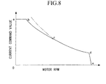
- FIG. 8 is a diagram showing an example of a motor rotation speed/current command value function for when an accelerator division in the battery forklift is at a maximum. This function is determined as follows.
- the motor rotation speed/current command value function corresponding to respective accelerator divisions is determined so as to obtain the desired torque and speed with respect to accelerator opening.
- the propulsion motor 4 is controlled to ensure a maximum speed, by reducing the current command value from point (d) to point (e)
- the current value for the propulsion motor 4 is determined from the current which gives a balance at the beforementioned duty ratio voltage corresponding to the steering angle, that is the angle subtended between the common axis of the two front wheels and the axis of the rear wheel. Consequently, at low speeds, the characteristic curves of the front wheel on the inside when turning (referred to hereunder as the inner wheel) and of the front wheel on the outside (referred to hereunder as the outer wheel) overlap, and hence both the inner and outer wheels have the same current value. Therefore, an undesirable influence is exerted on the feel during turning. Moreover, there is the problem of a reduction in turning efficiency attributable to friction etc. of the rear wheel.
- the present invention takes into consideration the above situation with the object of providing a propulsion motor control apparatus for a battery vehicle, which can improve the feel during turning and the turning efficiency even at low speeds, and thus realize optimum turning performance.
- the propulsion motor control apparatus for a battery vehicle being an apparatus which controls propulsion of a battery vehicle with a battery as a power source by individually controlling respective propulsion motors provided for two front wheels having a common axis, comprises; a steering angle detection device for detecting a steering angle subtended between the common axis of the two front wheels and an axis of a rear wheel, a ratio computing device for computing a ratio between a distance between an intersection point of the two axes and a first front wheel on a side further from the intersection point, and a distance between the intersection point and a second front wheel on a side closer to the intersection point, based on the steering angle, a function determining device for obtaining a motor rotation speed/current command value function for the second front wheel based on the motor rotation speed/current command value function for the first front wheel and the obtained ratio, and a control device for individually controlling the respective propulsion motors for the two front wheels based on the two functions.
- the propulsion motor control apparatus for a battery vehicle since this comprises; the steering angle detection device for detecting the steering angle subtended between the common axis of the two front wheels, and the axis of the rear wheel, the ratio computing device for computing the ratio between the distance between the intersection point of the two axes and the first front wheel on the side further from the intersection point, and the distance between the intersection point and the second front wheel on the side closer to the intersection point, based on the steering angle, the function determining device for obtaining the motor rotation speed/current command value function for the second front wheel based on the motor rotation speed/current command value function for the first front wheel and the obtained ratio, and the control device for individually controlling the respective propulsion motors for the two front wheels based on the two functions, then by outputting current command values independent of each other respectively for the first front wheel and the second front wheel, corresponding to the steering angle, the respective propulsion motors for the two front wheels can be individually controlled. Consequently, the feel during turning and the turning efficiency at low speeds can be improved, and
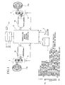
- FIG. 1 is a schematic diagram showing a three wheel battery forklift with two propulsion motors, according to an embodiment of the present invention.
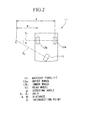
- FIG. 2 is an under surface view illustrating the positional relation between the front wheels and rear wheel of a battery forklift of the embodiment of the present invention.
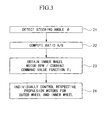
- FIG. 3 is flow chart illustrating the operation of a propulsion motor control apparatus for a battery forklift of the embodiment of the present invention.
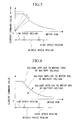
- FIG. 4 is a diagram showing motor rotation speed/current command value functions for respective outside and inside wheels according to the embodiment of the present invention.
- FIG. 5 is a diagram showing an example of a motor rotation speed/current command value function for a propulsion motor control apparatus of a conventional battery forklift.
- FIG. 6 is a diagram showing another example of a motor rotation speed/current command value function for a propulsion motor control apparatus of a conventional battery forklift.
- FIG. 7 is a schematic diagram showing a conventional three wheel battery forklift with two propulsion motors.
- FIG. 8 is diagram showing an example of a motor rotation speed/current command value function for a conventional three wheel battery forklift with two propulsion motors.
- FIG. 1 is a schematic diagram showing a three wheel battery forklift with two propulsion motors, according to the embodiment of the present invention
- FIG. 2 is an under surface view illustrating the positional relation between the front wheels and rear wheel of the battery forklift
- FIG. 3 is flow chart illustrating the operation of a propulsion motor control apparatus for the battery forklift.
- an angle sensor 21 (steering angle detection device) for detecting a steering angle ⁇ subtended between an axis X 1 common with an outer wheel (first front wheel) 12a and an inner wheel (second front wheel) 12b of a battery forklift 11, and an axis X 2 of a rear wheel 13, a ratio computing section (ratio computing device) 22 for computing a ratio A/B between a distance A from an intersection point C of the axis X 1 and the axis X 2 to the center of the outer wheel 12a, and a distance B from the intersection point C to the center of the inner wheel 12b, based on the steering angle ⁇ , a function setting section (function setting device) 23 for obtaining a motor rotation speed/current command value function for the inner wheel 12b based on the obtained motor rotation speed/current command function for the outer wheel 12a and the
- the steering angle ⁇ subtended between the axis X 1 common with the outer wheel 12a and the inner wheel 12b, and the axis X 2 of the rear wheel 13, is detected by the angle sensor 21.
- the ratio A/B between the distance A from the intersection point C of the axis X 1 and the axis X 2 to the center of the outer wheel 12a, and the distance B from the intersection point C to the center of the inner wheel 12b is computed based on the steering angle ⁇ .
- the vehicle stability, and feeling, such as under-steering and over-steering can be set to the optimum condition.
- the motor rotation speed/current command value function F 2 for the inner wheel 12b is obtained, based on the motor rotation speed/current command value function F 1 for the outer wheel 12a and the ratio A/B obtained from the ratio computing section 22.
- This motor rotation speed/current command value function F 2 is of a shape approximately resembling the motor rotation speed/current command value function F 1 for the outer wheel 12a.
- the respective propulsion motors 4 of the outer wheel 12a and the inner wheel 12b are individually controlled based on the motor rotation speed/current command value function F 1 for the outer wheel 12a and the motor rotation speed/current command value function F 2 for the inner wheel 12b. More specifically, a line L is drawn through the origin 0 and a point D on the motor rotation speed/current command value function F 1 corresponding to the current command value I 1 of the outer wheel 12a, and an intersection point E of the line L and the motor rotation speed/current command value function F 2 is obtained to thereby obtain a current command value I 2 for the inner wheel 12b corresponding to this intersection point E.
- the motor rotation speed/current command value function F 1 for the outer wheel 12a, and the motor rotation speed/current command value function F 2 for the inner wheel 12b do not overlap each other. Therefore a current command value I 1 is output to the propulsion motor 4a of the outer wheel 12a, and a current command value I 2 which is different from the current command value I 1 is output to the propulsion motor 4b of the inner wheel 12b, thereby enabling the outer wheel 12a to be rotated at a motor rotation speed R 1 , and the inner wheel 12b to be rotated at a motor rotation speed R 2 different from the motor rotation speed R 1 . As a result, the outer wheel 12a and the inner wheel 12b rotate at rotation speeds different from each other.
- independent current command values are respectively output to the propulsion motor 4a of the outer wheel 12a and the propulsion motor 4b of the inner wheel 12b, thereby enabling the propulsion motor 4a of the outer wheel 12a and the propulsion motor 4b of the inner wheel 12b to be individually controlled. Consequently, even at low speeds, the motor rotation speed/current command value function F 1 for the outer wheel 12a and the motor rotation speed/current command value function F 2 for the inner wheel 12b do not overlap each other, and hence the respective drives for the outer wheel 12a and the inner wheel 12b can be individually controlled at the torque and the rotation speed corresponding to the turning ratio A/B, so that the feel during turning, and turning efficiency are improved.
- the angle sensor 21 for detecting the steering angle ⁇ subtended between the axis X 1 common with the outer wheel 12a and the inner wheel 12b, and the axis X 2 of the rear wheel 13, the ratio computing section 22 for computing the ratio A/B between the distance A from the intersection point C of the axis X 1 and the axis X 2 to the outer wheel 12a, and the distance B from the intersection point C to the inner wheel 12b, based on the steering angle ⁇ , the function setting section 23 for obtaining the motor rotation speed/current command value function for the inner wheel 12b based on the obtained motor rotation speed/current command function for the outer wheel 12a and the obtained ratio A/B, and the control section 24 for individually controlling the propulsion motor 4a of the outer wheel 12a, and the propulsion motor 4b of the inner wheel 12b, based on the two functions.
- the respective rotational speeds of the outer wheel 12a and the inner wheel 12b can be individually controlled.
- the motor rotation speed/current command value function F 1 for the outer wheel 12a and the motor rotation speed/current command value function F 2 for the inner wheel 12b do not overlap each other.
- the feel during turning, and turning efficiency for the outer wheel 12a and the inner wheel 12b at low speeds can be improved, enabling optimum turning performance to be realized.
- the heretofore problem with the inner and outer wheels both having the same current value, the problem with the feel during turning, and the drop in turning efficiency attributable to friction etc. of the rear wheel can be overcome.
Abstract

Description
- The present invention relates to a propulsion motor control apparatus for a battery vehicle, and in particular to a propulsion motor control apparatus for a battery vehicle, ideally suited for use in a battery vehicle such as a battery forklift, which can realize optimum turning performance by improving feel during turning and turning efficiency even at low speeds.
- FIG. 5 shows an example of a motor rotation speed/current command value function for a conventional propulsion motor control apparatus for a battery forklift, and FIG. 6 shows another example of a motor rotation speed/current command value function for a conventional propulsion motor control apparatus for a battery forklift.
- Here the battery forklift is a vehicle which is propelled with a battery as the power source. With this battery forklift, the two front wheels have a common axis, and vehicle propulsion is controlled by individually controlling propulsion motors provided for each front wheel.
- As a means for adjusting the propulsion performance (propulsion feeling) of such a battery forklift, then as shown in FIG. 5, there is a device which effects adjustment, by increasing or decreasing a motor current limit value in the low speed region, or by changing the rising slope of the motor current value in the low speed region. Moreover, as another adjustment means, then as shown in FIG. 6, there is a device which makes the voltage applied to the motor in the middle speed region to high speed region constant by controlling a duty ratio of a PWM voltage with a battery voltage at 100%, to give for example 80% or 60% of the battery voltage.
- However, with the conventional propulsion motor control apparatus for a battery forklift as described above, various problems arise. For example, if the battery consumption, which is an important element of a battery forklift, is to be reduced, then if as shown in FIG. 5, the current in the low speed region is reduced, then the uphill power will be insufficient. Moreover, if as shown in FIG. 6, the fixed duty applied to the motor in the mid speed and high speed region is reduced, then the optimum speed will not be output.
- Therefore, the present inventor has proposed a control apparatus for a motor with a battery power source, which can obtain a sufficient output torque in the low speed region and which can at the same time reduce the battery consumption as much as possible, while ensuring a predetermined optimum speed (refer to Japanese Patent Application, First Publication, No. Hei 10-94114).
- FIG. 7 is a schematic diagram illustrating a three wheel battery forklift with two propulsion motors to which this control apparatus for a motor with a battery power source is applied. In FIG. 7,
numeral 1 denotes a battery, 2 an accelerator, 3 a propulsion motor control apparatus, 4 a propulsion motor, 5 a transmission unit, 6 a rotation sensor for detecting the rotation speed of thepropulsion motor 4, and 7 a front wheel of the forklift. Here for convenience sake, only onefront wheel 7 is shown. The other front wheel which is driven independently of thisfront wheel 7, is omitted from the figure. - FIG. 8 is a diagram showing an example of a motor rotation speed/current command value function for when an accelerator division in the battery forklift is at a maximum. This function is determined as follows.
- (1) Point (a) is determined from the specifications for maximum pulling power (uphill power) required for the battery forklift.
- (2) Point (c) is suitably determined in the mid speed region of the rotational speed range of
the propulsion motor 4 (horizontal axis in FIG. 8), with an intersection point of the rating
current of the
propulsion motor 4 and the motor rating output curve (the curve shown by the chain line in FIG. 8) as a criterion. A condition here is that, with the point (c), the chopper duty is at 100%, that is to say the battery power source voltage is applied to thepropulsion motor 4. - (3) Point (b) is a point on a straight line drawn parallel to the horizontal axis from the point
(a), and is the point that gives the same value battery current flow in the low speed region of
the rotational speed range of the
propulsion motor 4, as the battery current at the point (c). That is to say, in the low speed region, even in the case where the motor current (current command value) is large, it is possible to make the current supplied by thebattery 1 have the same value. The reason is that the current flows continuously via a free wheel diode of a chopper circuit for inertia of thepropulsion motor 4. Consequently, in this case, even if the duty is for example around 50%, a motor current of a current command value corresponding to the point (a) can be obtained.The characteristic curve from (b) to (c) may be determined in accordance with the above-mentioned determination method for the point (b). - (4) Point (d) is a point on the rating output curve for the
propulsion motor 4, and is the point corresponding to the limit speed of thepropulsion motor 4, that is to say to the limit speed of the battery forklift. Here the characteristic curve from (c) to (d) coincides with the rated output curve of thepropulsion motor 4. - (5) Point (e) is a point corresponding to a pre-load of the battery forklift.
-
- After determining the motor rotation speed/current command value function for the battery forklift by such a method, the motor rotation speed/current command value function corresponding to respective accelerator divisions is determined so as to obtain the desired torque and speed with respect to accelerator opening.
- With the motor rotation speed/current command value function determined in this way, then of course a desired maximum torque can be obtained. Moreover, in going from the low speed region to the middle speed region, that is from point (b) to point (c), by keeping the duty of the chopper circuit as small as possible, then the battery consumption can be controlled.
- Furthermore, while the characteristic curve from point (c) to point (d) is the rated output characteristic for the
propulsion motor 4, thepropulsion motor 4 is controlled to ensure a maximum speed, by reducing the current command value from point (d) to point (e) - Moreover, with the above described conventional battery forklift, since the voltage is controlled by duty controlling the
propulsion motor 4, then the current value for thepropulsion motor 4 is determined from the current which gives a balance at the beforementioned duty ratio voltage corresponding to the steering angle, that is the angle subtended between the common axis of the two front wheels and the axis of the rear wheel. Consequently, at low speeds, the characteristic curves of the front wheel on the inside when turning (referred to hereunder as the inner wheel) and of the front wheel on the outside (referred to hereunder as the outer wheel) overlap, and hence both the inner and outer wheels have the same current value. Therefore, an undesirable influence is exerted on the feel during turning. Moreover, there is the problem of a reduction in turning efficiency attributable to friction etc. of the rear wheel. - The present invention takes into consideration the above situation with the object of providing a propulsion motor control apparatus for a battery vehicle, which can improve the feel during turning and the turning efficiency even at low speeds, and thus realize optimum turning performance.
- In order to address the above problems, the propulsion motor control apparatus for a battery vehicle according to the present invention, being an apparatus which controls propulsion of a battery vehicle with a battery as a power source by individually controlling respective propulsion motors provided for two front wheels having a common axis, comprises; a steering angle detection device for detecting a steering angle subtended between the common axis of the two front wheels and an axis of a rear wheel, a ratio computing device for computing a ratio between a distance between an intersection point of the two axes and a first front wheel on a side further from the intersection point, and a distance between the intersection point and a second front wheel on a side closer to the intersection point, based on the steering angle, a function determining device for obtaining a motor rotation speed/current command value function for the second front wheel based on the motor rotation speed/current command value function for the first front wheel and the obtained ratio, and a control device for individually controlling the respective propulsion motors for the two front wheels based on the two functions.
- With the propulsion motor control apparatus for a battery vehicle according to the present invention, since this comprises; the steering angle detection device for detecting the steering angle subtended between the common axis of the two front wheels, and the axis of the rear wheel, the ratio computing device for computing the ratio between the distance between the intersection point of the two axes and the first front wheel on the side further from the intersection point, and the distance between the intersection point and the second front wheel on the side closer to the intersection point, based on the steering angle, the function determining device for obtaining the motor rotation speed/current command value function for the second front wheel based on the motor rotation speed/current command value function for the first front wheel and the obtained ratio, and the control device for individually controlling the respective propulsion motors for the two front wheels based on the two functions, then by outputting current command values independent of each other respectively for the first front wheel and the second front wheel, corresponding to the steering angle, the respective propulsion motors for the two front wheels can be individually controlled. Consequently, the feel during turning and the turning efficiency at low speeds can be improved, and optimum turning performance can be realized.
- FIG. 1 is a schematic diagram showing a three wheel battery forklift with two propulsion motors, according to an embodiment of the present invention.
- FIG. 2 is an under surface view illustrating the positional relation between the front wheels and rear wheel of a battery forklift of the embodiment of the present invention.
- FIG. 3 is flow chart illustrating the operation of a propulsion motor control apparatus for a battery forklift of the embodiment of the present invention.
- FIG. 4 is a diagram showing motor rotation speed/current command value functions for respective outside and inside wheels according to the embodiment of the present invention.
- FIG. 5 is a diagram showing an example of a motor rotation speed/current command value function for a propulsion motor control apparatus of a conventional battery forklift.
- FIG. 6 is a diagram showing another example of a motor rotation speed/current command value function for a propulsion motor control apparatus of a conventional battery forklift.
- FIG. 7 is a schematic diagram showing a conventional three wheel battery forklift with two propulsion motors.
- FIG. 8 is diagram showing an example of a motor rotation speed/current command value function for a conventional three wheel battery forklift with two propulsion motors.
- An embodiment of a propulsion motor control apparatus for a battery vehicle according to the present invention will now be described with reference to the drawings.
- FIG. 1 is a schematic diagram showing a three wheel battery forklift with two propulsion motors, according to the embodiment of the present invention, FIG. 2 is an under surface view illustrating the positional relation between the front wheels and rear wheel of the battery forklift, and FIG. 3 is flow chart illustrating the operation of a propulsion motor control apparatus for the battery forklift.
- The point where the construction of this battery forklift differs from the construction of the above-mentioned conventional battery forklift is that, with the propulsion motor control apparatus 3, there is provided; an angle sensor 21 (steering angle detection device) for detecting a steering angle subtended between an axis X1 common with an outer wheel (first front wheel) 12a and an inner wheel (second front wheel) 12b of a battery forklift 11, and an axis X2 of a
rear wheel 13, a ratio computing section (ratio computing device) 22 for computing a ratio A/B between a distance A from an intersection point C of the axis X1 and the axis X2 to the center of theouter wheel 12a, and a distance B from the intersection point C to the center of theinner wheel 12b, based on the steering angle , a function setting section (function setting device) 23 for obtaining a motor rotation speed/current command value function for theinner wheel 12b based on the obtained motor rotation speed/current command function for theouter wheel 12a and the obtained ratio A/B , and a control section (control device) 24 for individually controlling thepropulsion motor 4a of theouter wheel 12a, and thepropulsion motor 4b of theinner wheel 12b, based on the two functions. - With this propulsion motor control apparatus, as shown in FIG. 3, the steering angle subtended between the axis X1 common with the
outer wheel 12a and theinner wheel 12b, and the axis X2 of therear wheel 13, is detected by theangle sensor 21. Then by means of theratio computing section 22, the ratio A/B between the distance A from the intersection point C of the axis X1 and the axis X2 to the center of theouter wheel 12a, and the distance B from the intersection point C to the center of theinner wheel 12b is computed based on the steering angle . Here, by intentionally changing the steering angle , that is to say the ratio A/B, then the vehicle stability, and feeling, such as under-steering and over-steering can be set to the optimum condition. - Then, as shown in FIG. 4, by means of the
function setting section 23, the motor rotation speed/current command value function F2 for theinner wheel 12b is obtained, based on the motor rotation speed/current command value function F1 for theouter wheel 12a and the ratio A/B obtained from theratio computing section 22. This motor rotation speed/current command value function F2 is of a shape approximately resembling the motor rotation speed/current command value function F1 for theouter wheel 12a. - Next, by means of the
control section 24, therespective propulsion motors 4 of theouter wheel 12a and theinner wheel 12b are individually controlled based on the motor rotation speed/current command value function F1 for theouter wheel 12a and the motor rotation speed/current command value function F2 for theinner wheel 12b. More specifically, a line L is drawn through theorigin 0 and a point D on the motor rotation speed/current command value function F1 corresponding to the current command value I1 of theouter wheel 12a, and an intersection point E of the line L and the motor rotation speed/current command value function F2 is obtained to thereby obtain a current command value I2 for theinner wheel 12b corresponding to this intersection point E. - Here, the motor rotation speed/current command value function F1 for the
outer wheel 12a, and the motor rotation speed/current command value function F2 for theinner wheel 12b do not overlap each other. Therefore a current command value I1 is output to thepropulsion motor 4a of theouter wheel 12a, and a current command value I2 which is different from the current command value I1 is output to thepropulsion motor 4b of theinner wheel 12b, thereby enabling theouter wheel 12a to be rotated at a motor rotation speed R1, and theinner wheel 12b to be rotated at a motor rotation speed R2 different from the motor rotation speed R1. As a result, theouter wheel 12a and theinner wheel 12b rotate at rotation speeds different from each other. - In this way, independent current command values are respectively output to the
propulsion motor 4a of theouter wheel 12a and thepropulsion motor 4b of theinner wheel 12b, thereby enabling thepropulsion motor 4a of theouter wheel 12a and thepropulsion motor 4b of theinner wheel 12b to be individually controlled. Consequently, even at low speeds, the motor rotation speed/current command value function F1 for theouter wheel 12a and the motor rotation speed/current command value function F2 for theinner wheel 12b do not overlap each other, and hence the respective drives for theouter wheel 12a and theinner wheel 12b can be individually controlled at the torque and the rotation speed corresponding to the turning ratio A/B, so that the feel during turning, and turning efficiency are improved. - As described above, with the present embodiment, in the propulsion motor control apparatus 3 there is provided; the
angle sensor 21 for detecting the steering angle subtended between the axis X1 common with theouter wheel 12a and theinner wheel 12b, and the axis X2 of therear wheel 13, theratio computing section 22 for computing the ratio A/B between the distance A from the intersection point C of the axis X1 and the axis X2 to theouter wheel 12a, and the distance B from the intersection point C to theinner wheel 12b, based on the steering angle , thefunction setting section 23 for obtaining the motor rotation speed/current command value function for theinner wheel 12b based on the obtained motor rotation speed/current command function for theouter wheel 12a and the obtained ratio A/B, and thecontrol section 24 for individually controlling thepropulsion motor 4a of theouter wheel 12a, and thepropulsion motor 4b of theinner wheel 12b, based on the two functions. Hence the respective rotational speeds of theouter wheel 12a and theinner wheel 12b can be individually controlled. - Consequently, even at low speeds, the motor rotation speed/current command value function F1 for the
outer wheel 12a and the motor rotation speed/current command value function F2 for theinner wheel 12b do not overlap each other. Hence it is possible to control at the torque and the rotation speed corresponding to the turning ratio A/B, so that the feel during turning, and turning efficiency for theouter wheel 12a and theinner wheel 12b at low speeds can be improved, enabling optimum turning performance to be realized. As a result, the heretofore problem with the inner and outer wheels both having the same current value, the problem with the feel during turning, and the drop in turning efficiency attributable to friction etc. of the rear wheel can be overcome. - In the above, one embodiment of a propulsion motor control apparatus for a battery vehicle according to the present invention has been described, based on the drawings. However the specific construction is not limited to the present embodiment, and designs and modifications etc. within a scope not deviating from the gist of the invention are also possible. For example the basic numerical values and ranges etc. for the steering angle and the ratio A/B can be suitably set as required.
Claims (3)
- A propulsion motor control apparatus for a battery vehicle (1), being an apparatus which controls propulsion of a battery vehicle with a battery as a power source by individually controlling respective propulsion motors (4a, 4b) provided for two front wheels (12a, 12b) having a common axis (X1), characterized in that said apparatus comprises;
steering angle detection means (21) for detecting a steering angle () subtended between said common axis (X1) of the two front wheels (12a, 12b), and an axis (X2) of a rear wheel, ratio computing means (22) for computing a ratio between a distance between an intersection point (C) of said two axes (X1, X2) and a first front wheel (12a) on a side further from said intersection point (C), and a distance between said intersection point (C) and a second front wheel (12b) on a side closer to said intersection point (C), based on said steering angle (), function determining means (23) for obtaining a motor rotation speed/current command value function (F2) for said second front wheel (12b) based on a motor rotation speed/current command value function (F1) for said first front wheel (12a) and said obtained ratio, and control means (24) for individually controlling said respective propulsion motors (4a, 4b) for said two front wheels (12a, 12b) based on said two functions (F1, F2). - A propulsion motor control apparatus for a battery vehicle according to claim 1, characterized in that said control means (24) controls the respective motor rotation speeds (R1, R2) of said two front wheels (12a, 12b) independent of each other, based on respective current command values (I1, I2) for said two front wheels (12a, 12b).
- A propulsion motor control apparatus for a battery vehicle according to either one of claim 1 and claim 2, characterized in that the motor rotation speed/current command value function (F1) for said first front wheel (12a) at the time of deceleration, and the motor rotation speed/current command value function (F2) for said second front wheel (12b) at the time of deceleration, do not overlap.
Applications Claiming Priority (2)
| Application Number | Priority Date | Filing Date | Title |
|---|---|---|---|
| JP23773398A JP3842904B2 (en) | 1998-08-24 | 1998-08-24 | Battery motor travel motor control device |
| JP23773398 | 1998-08-24 |
Publications (3)
| Publication Number | Publication Date |
|---|---|
| EP0982220A2 true EP0982220A2 (en) | 2000-03-01 |
| EP0982220A3 EP0982220A3 (en) | 2001-03-21 |
| EP0982220B1 EP0982220B1 (en) | 2008-09-03 |
Family
ID=17019680
Family Applications (1)
| Application Number | Title | Priority Date | Filing Date |
|---|---|---|---|
| EP99400468A Expired - Lifetime EP0982220B1 (en) | 1998-08-24 | 1999-02-26 | Propulsion motor control apparatus for battery vehicle |
Country Status (4)
| Country | Link |
|---|---|
| US (1) | US6386305B2 (en) |
| EP (1) | EP0982220B1 (en) |
| JP (1) | JP3842904B2 (en) |
| DE (1) | DE69939445D1 (en) |
Cited By (9)
| Publication number | Priority date | Publication date | Assignee | Title |
|---|---|---|---|---|
| WO2002000462A1 (en) * | 2000-06-28 | 2002-01-03 | Prodrive 2000 Limited | Hybrid vehicle drive system |
| EP1213198A1 (en) * | 2000-12-06 | 2002-06-12 | Ford Global Technologies, Inc. | Steering control device for a vehicle and method for operating said device |
| GB2345895B (en) * | 1999-01-22 | 2002-12-18 | Rover Group | A vehicle |
| FR2872771A1 (en) * | 2004-07-07 | 2006-01-13 | Giat Ind Sa | MIXED DIRECTION METHOD FOR ELECTRIC PROPULSION VEHICLE |
| EP2133232A1 (en) * | 2008-06-13 | 2009-12-16 | Industrial Technology Research Institute | Electric vehicle and control method thereof |
| JP2015211526A (en) * | 2014-04-25 | 2015-11-24 | 株式会社豊田自動織機 | Industrial vehicle |
| CN109160455A (en) * | 2018-11-12 | 2019-01-08 | 杭叉集团股份有限公司 | Large-tonnage electric forklift and its double-motor driving device |
| CN110116779A (en) * | 2018-02-06 | 2019-08-13 | 株式会社美姿把 | Drive dynamic control device and drive control method |
| WO2019185436A1 (en) * | 2018-03-28 | 2019-10-03 | Hubtex Maschinenbau Gmbh & Co. Kg | Transport vehicle |
Families Citing this family (7)
| Publication number | Priority date | Publication date | Assignee | Title |
|---|---|---|---|---|
| US20030061611A1 (en) * | 2001-09-26 | 2003-03-27 | Ramesh Pendakur | Notifying users of available content and content reception based on user profiles |
| DE10343640B4 (en) * | 2003-09-20 | 2016-12-29 | Deere & Company | Steering system for an agricultural or industrial utility vehicle |
| EP1773646A2 (en) * | 2004-01-09 | 2007-04-18 | Electric Mobility Corporation | Vehicle with improved turning |
| CN104244796B (en) | 2012-05-03 | 2017-08-11 | Nss 企业公司 | Dual drive floor scrubber |
| US9246419B2 (en) * | 2013-02-06 | 2016-01-26 | Samsung Sdi Co., Ltd. | Method and system for controlling motor |
| CN104736425B (en) * | 2013-06-19 | 2017-03-22 | 株式会社日本艾莱克托克 | Automatic three-wheeled vehicle |
| US9635990B2 (en) | 2014-11-18 | 2017-05-02 | Nss Enterprises, Inc. | Floor cleaning or burnishing machine pivot suspension |
Citations (1)
| Publication number | Priority date | Publication date | Assignee | Title |
|---|---|---|---|---|
| JPH0194114A (en) | 1987-10-05 | 1989-04-12 | Ohbayashi Corp | Roughening work for downside of preceding concrete in inverted concrete placing work |
Family Cites Families (16)
| Publication number | Priority date | Publication date | Assignee | Title |
|---|---|---|---|---|
| JPS5364317A (en) * | 1976-11-17 | 1978-06-08 | Meidensha Electric Mfg Co Ltd | Electric vehicle |
| JPS5911242B2 (en) * | 1976-12-18 | 1984-03-14 | 三菱電機株式会社 | Electric vehicle chip control device |
| US4320810A (en) | 1979-12-17 | 1982-03-23 | Chromalloy American Corporation | Vehicle with improved steering system device |
| JPS56153904A (en) * | 1980-04-29 | 1981-11-28 | Mitsubishi Electric Corp | Controlling method for electric motor vehicle |
| US4471273A (en) * | 1983-01-05 | 1984-09-11 | Towmotor Corporation | Dual-motor control apparatus |
| US5206574A (en) * | 1986-05-02 | 1993-04-27 | Nec Corporation | Vector control apparatus for induction motor |
| JPS631306A (en) * | 1986-06-20 | 1988-01-06 | Hitachi Ltd | Chopper control system |
| DE8709996U1 (en) * | 1987-07-22 | 1988-11-17 | Meyra Wilhelm Meyer Gmbh & Co Kg, 4973 Vlotho, De | |
| US5465806A (en) * | 1989-03-31 | 1995-11-14 | Kabushiki Kaisha Shikoku Sogo Kenkyujo | Electric vehicle |
| US5383528A (en) * | 1992-01-30 | 1995-01-24 | Nicol; Alexander | Drive system having a linkage for controlling the operation of groundwheels in a motor vehicle |
| US5343974A (en) * | 1992-07-10 | 1994-09-06 | Rabek Jan W | An electrically powered motor vehicle |
| GB9310036D0 (en) * | 1993-05-15 | 1993-06-30 | Solaria Ind Inc | Electrical powered small tractor |
| DE4431305C2 (en) * | 1994-09-02 | 2000-11-23 | Auwaerter Gottlob Gmbh & Co | omnibus |
| JPH09240477A (en) | 1996-03-06 | 1997-09-16 | Yamaha Motor Co Ltd | Motor-driven carriage |
| JP3477324B2 (en) | 1996-09-11 | 2003-12-10 | 三菱重工業株式会社 | Battery-powered motor controller |
| US5923096A (en) * | 1997-04-18 | 1999-07-13 | Manak Dynamics Engineering Corp. | All-electric vehicle control system |
-
1998
- 1998-08-24 JP JP23773398A patent/JP3842904B2/en not_active Expired - Fee Related
-
1999
- 1999-02-25 US US09/257,190 patent/US6386305B2/en not_active Expired - Lifetime
- 1999-02-26 DE DE69939445T patent/DE69939445D1/en not_active Expired - Lifetime
- 1999-02-26 EP EP99400468A patent/EP0982220B1/en not_active Expired - Lifetime
Patent Citations (1)
| Publication number | Priority date | Publication date | Assignee | Title |
|---|---|---|---|---|
| JPH0194114A (en) | 1987-10-05 | 1989-04-12 | Ohbayashi Corp | Roughening work for downside of preceding concrete in inverted concrete placing work |
Cited By (11)
| Publication number | Priority date | Publication date | Assignee | Title |
|---|---|---|---|---|
| GB2345895B (en) * | 1999-01-22 | 2002-12-18 | Rover Group | A vehicle |
| WO2002000462A1 (en) * | 2000-06-28 | 2002-01-03 | Prodrive 2000 Limited | Hybrid vehicle drive system |
| EP1213198A1 (en) * | 2000-12-06 | 2002-06-12 | Ford Global Technologies, Inc. | Steering control device for a vehicle and method for operating said device |
| US6612394B2 (en) | 2000-12-06 | 2003-09-02 | Ford Global Technologies, Llc | Steering control device for a vehicle and method for operating said device |
| FR2872771A1 (en) * | 2004-07-07 | 2006-01-13 | Giat Ind Sa | MIXED DIRECTION METHOD FOR ELECTRIC PROPULSION VEHICLE |
| EP2133232A1 (en) * | 2008-06-13 | 2009-12-16 | Industrial Technology Research Institute | Electric vehicle and control method thereof |
| JP2015211526A (en) * | 2014-04-25 | 2015-11-24 | 株式会社豊田自動織機 | Industrial vehicle |
| CN110116779A (en) * | 2018-02-06 | 2019-08-13 | 株式会社美姿把 | Drive dynamic control device and drive control method |
| WO2019185436A1 (en) * | 2018-03-28 | 2019-10-03 | Hubtex Maschinenbau Gmbh & Co. Kg | Transport vehicle |
| US11851312B2 (en) | 2018-03-28 | 2023-12-26 | Hubtex Maschinenbau Gmbh & Co. Kg | Transport vehicle |
| CN109160455A (en) * | 2018-11-12 | 2019-01-08 | 杭叉集团股份有限公司 | Large-tonnage electric forklift and its double-motor driving device |
Also Published As
| Publication number | Publication date |
|---|---|
| EP0982220A3 (en) | 2001-03-21 |
| EP0982220B1 (en) | 2008-09-03 |
| DE69939445D1 (en) | 2008-10-16 |
| JP2000069613A (en) | 2000-03-03 |
| US6386305B2 (en) | 2002-05-14 |
| JP3842904B2 (en) | 2006-11-08 |
| US20020014360A1 (en) | 2002-02-07 |
Similar Documents
| Publication | Publication Date | Title |
|---|---|---|
| US6386305B2 (en) | Propulsion motor control apparatus for battery vehicle | |
| US6617704B2 (en) | Hybrid vehicle control apparatus | |
| JP4857952B2 (en) | Electric drive vehicle | |
| US5545106A (en) | Method for adjusting the transmission ratio of a transmission | |
| US5151860A (en) | Control method for electric power steering apparatus for vehicle | |
| JPH0993714A (en) | Driver for electric vehicle | |
| US5374877A (en) | Apparatus and method of controlling power of electric motor car | |
| JP2704804B2 (en) | Vehicle traction control device | |
| EP1407958B1 (en) | Control apparatus for an electric power steering system | |
| JPH07298514A (en) | Controller for alternator in vehicle | |
| EP0982175B1 (en) | Regenerative braking apparatus for battery vehicle | |
| JPH1073033A (en) | Driving force control device of vehicle | |
| JPH10151965A (en) | Maximum speed limiting device | |
| JPH0993724A (en) | Electric automobile | |
| JPH11255134A (en) | Electric hydraulic power steering device | |
| EP1323620B1 (en) | Electric power steering apparatus | |
| JP3588818B2 (en) | Power train control device during turning of vehicle | |
| JP2001247048A (en) | Electric power steering control device | |
| JPH06153324A (en) | Electric automobile | |
| JP3240960B2 (en) | Steering device | |
| EP0444672A1 (en) | Speed controller of electric-motor vehicle | |
| JP2773527B2 (en) | Power generation control device for vehicles | |
| JP2010111253A (en) | Electric power steering control device | |
| JP3332034B2 (en) | Vehicle driving force control device and control method | |
| JP2879766B2 (en) | Power steering device for electric wheelchair |
Legal Events
| Date | Code | Title | Description |
|---|---|---|---|
| PUAI | Public reference made under article 153(3) epc to a published international application that has entered the european phase |
Free format text: ORIGINAL CODE: 0009012 |
|
| 17P | Request for examination filed |
Effective date: 19990316 |
|
| AK | Designated contracting states |
Kind code of ref document: A2 Designated state(s): DE FR GB IT |
|
| AX | Request for extension of the european patent |
Free format text: AL;LT;LV;MK;RO;SI |
|
| PUAL | Search report despatched |
Free format text: ORIGINAL CODE: 0009013 |
|
| AK | Designated contracting states |
Kind code of ref document: A3 Designated state(s): AT BE CH CY DE DK ES FI FR GB GR IE IT LI LU MC NL PT SE |
|
| AX | Request for extension of the european patent |
Free format text: AL;LT;LV;MK;RO;SI |
|
| AKX | Designation fees paid |
Free format text: DE FR GB IT |
|
| 17Q | First examination report despatched |
Effective date: 20030127 |
|
| 17Q | First examination report despatched |
Effective date: 20030127 |
|
| GRAP | Despatch of communication of intention to grant a patent |
Free format text: ORIGINAL CODE: EPIDOSNIGR1 |
|
| RIC1 | Information provided on ipc code assigned before grant |
Ipc: B62D 11/04 20060101ALI20080110BHEP Ipc: B62D 6/00 20060101ALI20080110BHEP Ipc: B62D 9/00 20060101AFI20080110BHEP |
|
| GRAS | Grant fee paid |
Free format text: ORIGINAL CODE: EPIDOSNIGR3 |
|
| GRAA | (expected) grant |
Free format text: ORIGINAL CODE: 0009210 |
|
| AK | Designated contracting states |
Kind code of ref document: B1 Designated state(s): DE FR GB IT |
|
| REG | Reference to a national code |
Ref country code: GB Ref legal event code: FG4D |
|
| REF | Corresponds to: |
Ref document number: 69939445 Country of ref document: DE Date of ref document: 20081016 Kind code of ref document: P |
|
| PLBE | No opposition filed within time limit |
Free format text: ORIGINAL CODE: 0009261 |
|
| STAA | Information on the status of an ep patent application or granted ep patent |
Free format text: STATUS: NO OPPOSITION FILED WITHIN TIME LIMIT |
|
| 26N | No opposition filed |
Effective date: 20090604 |
|
| REG | Reference to a national code |
Ref country code: DE Ref legal event code: R082 Ref document number: 69939445 Country of ref document: DE Representative=s name: PATENTANWAELTE BETTEN & RESCH, DE |
|
| REG | Reference to a national code |
Ref country code: DE Ref legal event code: R082 Ref document number: 69939445 Country of ref document: DE Representative=s name: BETTEN & RESCH PATENT- UND RECHTSANWAELTE PART, DE Effective date: 20130702 Ref country code: DE Ref legal event code: R082 Ref document number: 69939445 Country of ref document: DE Representative=s name: PATENTANWAELTE BETTEN & RESCH, DE Effective date: 20130702 Ref country code: DE Ref legal event code: R081 Ref document number: 69939445 Country of ref document: DE Owner name: MITSUBISHI NICHIYU FORKLIFT CO., LTD., NAGAOKA, JP Free format text: FORMER OWNER: MITSUBISHI HEAVY INDUSTRIES, LTD., TOKYO, JP Effective date: 20130702 Ref country code: DE Ref legal event code: R081 Ref document number: 69939445 Country of ref document: DE Owner name: MITSUBISHI NICHIYU FORKLIFT CO., LTD., JP Free format text: FORMER OWNER: MITSUBISHI HEAVY INDUSTRIES, LTD., TOKYO, JP Effective date: 20130702 |
|
| REG | Reference to a national code |
Ref country code: FR Ref legal event code: TP Owner name: MITSUBISHI NICHIYU FORKLIFT CO., LTD., JP Effective date: 20130729 |
|
| REG | Reference to a national code |
Ref country code: GB Ref legal event code: 732E Free format text: REGISTERED BETWEEN 20130815 AND 20130821 |
|
| REG | Reference to a national code |
Ref country code: FR Ref legal event code: PLFP Year of fee payment: 17 |
|
| PGFP | Annual fee paid to national office [announced via postgrant information from national office to epo] |
Ref country code: IT Payment date: 20150218 Year of fee payment: 17 Ref country code: DE Payment date: 20150218 Year of fee payment: 17 |
|
| PGFP | Annual fee paid to national office [announced via postgrant information from national office to epo] |
Ref country code: GB Payment date: 20150225 Year of fee payment: 17 Ref country code: FR Payment date: 20150210 Year of fee payment: 17 |
|
| REG | Reference to a national code |
Ref country code: DE Ref legal event code: R119 Ref document number: 69939445 Country of ref document: DE |
|
| GBPC | Gb: european patent ceased through non-payment of renewal fee |
Effective date: 20160226 |
|
| REG | Reference to a national code |
Ref country code: FR Ref legal event code: ST Effective date: 20161028 |
|
| PG25 | Lapsed in a contracting state [announced via postgrant information from national office to epo] |
Ref country code: IT Free format text: LAPSE BECAUSE OF NON-PAYMENT OF DUE FEES Effective date: 20160226 |
|
| PG25 | Lapsed in a contracting state [announced via postgrant information from national office to epo] |
Ref country code: FR Free format text: LAPSE BECAUSE OF NON-PAYMENT OF DUE FEES Effective date: 20160229 Ref country code: DE Free format text: LAPSE BECAUSE OF NON-PAYMENT OF DUE FEES Effective date: 20160901 Ref country code: GB Free format text: LAPSE BECAUSE OF NON-PAYMENT OF DUE FEES Effective date: 20160226 |