EP0444672A1 - Speed controller of electric-motor vehicle - Google Patents
Speed controller of electric-motor vehicle Download PDFInfo
- Publication number
- EP0444672A1 EP0444672A1 EP91103015A EP91103015A EP0444672A1 EP 0444672 A1 EP0444672 A1 EP 0444672A1 EP 91103015 A EP91103015 A EP 91103015A EP 91103015 A EP91103015 A EP 91103015A EP 0444672 A1 EP0444672 A1 EP 0444672A1
- Authority
- EP
- European Patent Office
- Prior art keywords
- motor
- signal
- output voltage
- output
- speed
- Prior art date
- Legal status (The legal status is an assumption and is not a legal conclusion. Google has not performed a legal analysis and makes no representation as to the accuracy of the status listed.)
- Granted
Links
Images


Classifications
-
- B—PERFORMING OPERATIONS; TRANSPORTING
- B60—VEHICLES IN GENERAL
- B60L—PROPULSION OF ELECTRICALLY-PROPELLED VEHICLES; SUPPLYING ELECTRIC POWER FOR AUXILIARY EQUIPMENT OF ELECTRICALLY-PROPELLED VEHICLES; ELECTRODYNAMIC BRAKE SYSTEMS FOR VEHICLES IN GENERAL; MAGNETIC SUSPENSION OR LEVITATION FOR VEHICLES; MONITORING OPERATING VARIABLES OF ELECTRICALLY-PROPELLED VEHICLES; ELECTRIC SAFETY DEVICES FOR ELECTRICALLY-PROPELLED VEHICLES
- B60L50/00—Electric propulsion with power supplied within the vehicle
- B60L50/50—Electric propulsion with power supplied within the vehicle using propulsion power supplied by batteries or fuel cells
- B60L50/52—Electric propulsion with power supplied within the vehicle using propulsion power supplied by batteries or fuel cells characterised by DC-motors
-
- Y—GENERAL TAGGING OF NEW TECHNOLOGICAL DEVELOPMENTS; GENERAL TAGGING OF CROSS-SECTIONAL TECHNOLOGIES SPANNING OVER SEVERAL SECTIONS OF THE IPC; TECHNICAL SUBJECTS COVERED BY FORMER USPC CROSS-REFERENCE ART COLLECTIONS [XRACs] AND DIGESTS
- Y02—TECHNOLOGIES OR APPLICATIONS FOR MITIGATION OR ADAPTATION AGAINST CLIMATE CHANGE
- Y02T—CLIMATE CHANGE MITIGATION TECHNOLOGIES RELATED TO TRANSPORTATION
- Y02T10/00—Road transport of goods or passengers
- Y02T10/60—Other road transportation technologies with climate change mitigation effect
- Y02T10/70—Energy storage systems for electromobility, e.g. batteries
-
- Y—GENERAL TAGGING OF NEW TECHNOLOGICAL DEVELOPMENTS; GENERAL TAGGING OF CROSS-SECTIONAL TECHNOLOGIES SPANNING OVER SEVERAL SECTIONS OF THE IPC; TECHNICAL SUBJECTS COVERED BY FORMER USPC CROSS-REFERENCE ART COLLECTIONS [XRACs] AND DIGESTS
- Y02—TECHNOLOGIES OR APPLICATIONS FOR MITIGATION OR ADAPTATION AGAINST CLIMATE CHANGE
- Y02T—CLIMATE CHANGE MITIGATION TECHNOLOGIES RELATED TO TRANSPORTATION
- Y02T10/00—Road transport of goods or passengers
- Y02T10/60—Other road transportation technologies with climate change mitigation effect
- Y02T10/72—Electric energy management in electromobility
Definitions
- This invention relates to an apparatus for controlling the traveling speed of an electric-motor vehicle, and particularly to a speed controller of an electric-motor vehicle suitably used for controlling the speed of an electric-motor wheeled chair or the like which is limited in maximum speed.
- the maximum speed of, for example, an electric-motor wheeled chair among electric-motor vehicles is restricted in maximum speed under the laws.
- the maximum speed is restricted by such means as that a certain torque value of a traveling motor, such as the number of rotation of the motor in a driving torque corresponding to a traveling state of a vehicle on a flat road is restrained to a constant value to determine the maximum speed or the number of rotation of the traveling motor is detected using a sensor and a closed-loop control is performed by feeding back such detected number.
- a certain torque value of a traveling motor such as the number of rotation of the motor in a driving torque corresponding to a traveling state of a vehicle on a flat road is restrained to a constant value to determine the maximum speed or the number of rotation of the traveling motor is detected using a sensor and a closed-loop control is performed by feeding back such detected number.
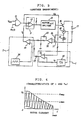
- Fig. 6 shows one example of the constitution of a conventional speed controller of an electric-motor vehicle.
- the numeral 11 denotes a variable resistor connected to an operating lever of an electric-motor wheeled chair, 12 an absolute value amplifier, 13 a comparator, 14 an operational amplifier, 15 a motor driver, 16 a driving transistor, 17 a power source comprising a battery, 18 a traveling motor, 19 a current detecting shunt, 20 a resistance, 21 a condenser, 22 an operational amplifier, 23 a constant voltage diode, and 24 a reference chopping signal generator, respectively.
- the variable resistor 11 is connected to a space between a power source voltage V CC and the ground and generates an output voltage (voltage of an accelerator) V ACC corresponding to the amount of operation (opening degree of the accelerator) of the unshown operating lever.
- This output voltage V ACC is V CC /2 at an intermediate position (neutral state of the operating lever) and becomes larger or smaller depending on forward or reverse.
- the output voltage V ACC serves as a drive indicating signal for the speed controller for an electric-motor vehicle.
- the output voltage of the variable resistor 11 is also subjected to the use of other purposes than forward and reverse discrimination.
- the absolute value circuit 12 generates an output voltage, the amount of which is proportional to the forward or reverse speed, by amplifying the absolute value of a difference between the output voltage of the variable resistor 11 and the reference voltage V CC/2 and this signal is fed to the "+" input side of the comparator 13.
- a current value of the motor 18 is detected by the current detecting shunt 19 which is connected in series to the motor 18 and a signal obtained by a circuit comprising the resistance 20 and the condenser 21 in a DC form is amplified by the operational amplifier 22 in order to obtain an output voltage.
- the output voltage of the operational amplifier 22 is fed to the "-" input side of the operational amplifier 14 through the constant voltage diode 23.
- the operational amplifier 14 As the operational amplifier 14 is operated as a differential amplifier and a reference chopping signal from the chopping signal generator 24 is fed to the "+" input side of the amplifier 14, the operational amplifier 14 generates an output voltage V O comprising a chopping signal which is varied in width and amplitude in accordance with a period of time during which the chopping signal exceeds the output voltage of the operational amplifier 22 which is fed through the constant voltage diode 23. This signal is fed to the "-" input side of the comparator 13.
- the comparator 13 generates a PWM signal which is varied in pulse width in accordance with the adjusting position of the variable resistor 11 by outputting a signal when output of the absolute value amplifying circuit 12 is larger than the chopping signal output of the operational amplifier 14.
- the motor driver 15 controls the transistor 16 in accordance with the output of the comparator 13. By this, a chopper control current flows to the motor 18 from the power source 17 via the transistor 16 and the motor 18 is rotated to cause the electric-motor wheeled chair to travel.
- a chopping signal obtained by the operational amplifier 14 from a difference between an output signal obtained by amplifying a voltage proportional to current i of the motor and the reference chopping signal is used as a voltage V O to be compared with an output of the absolute value amplifying circuit 12 in the comparator 13.
- the constant voltage diode 23 is adapted to enhance the traveling stability when the load is not heavy to obtain a comfortable feeling (comfortable to drive) by keeping the duty unchanged at a low driving current time of the motor 18.
- Fig. 7 shows the characteristics of the motor current i and the output voltage V O of the operational amplifier 14 in the example of the constitution (or block diagram) of Fig. 6.
- the motor current i flows corresponding to a period of time during which the output voltage V O comprising a chopping wave is small compared with an absolute value amplifying circuit output H max corresponding to the maximum value in a high speed range as shown by a broken line and with an absolute value amplifying circuit output L max corresponding to the maximum value of the accelerator in a low speed range as shown likewise by a broken line
- the duty gradually becomes large when the motor current i is large, and the duty becomes 100% at a certain motor current or more particularly when the motor is in a high speed range.
- the range where the motor current i is small there is a range A where the duty becomes constant irrespective of change in load (motor current) both in high speed and low speed ranges owing to the affection of the constant voltage diode 23.
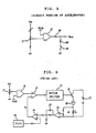
- Fig. 8 shows another example of the constitution (or block diagram) of a conventional speed controller of an electric-motor vehicle, wherein like parts of Fig. 6 are denoted by like reference numerals.
- the numeral 25 denotes a frequency/voltage (F/V) converter.
- an output voltage V F of the size proportional to the number of rotation of the motor 18 is generated by the F/V converter 25 in accordance with the pulse from a rotation sensor disposed to the motor 18.
- the comparator 13 takes off a difference between this and the output voltage of the absolute value amplifying circuit 12 already applied to the "+" input side. By the voltage of this difference, the transistor 16 is driven through the motor driver 15m thereby to control the flow of current to the motor 18.
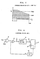
- Fig. 9 shows the characteristics of the rotational number N of the motor and the output voltage V F of the F/V converter 25 in the example of Fig. 8. Since a ripple is included in the output voltage V F of the F/V converter 25, it exhibits the illustrated output characteristics. In this case, the smaller the rotational number N of the motor is, the greater the affection of the ripple becomes.
- the duty of the motor driving current does not become 100% in the low speed range and in the range where the opening degree of the accelerator is small and the driving force of the motor is in short.
- the gain of the operational amplifier 22 of Fig. 6 is made large, so that the "-" input side of the operational amplifier becomes large when the motor current becomes large.
- to make the gain of the feed-back loop small is to effect a large amount of such compensation as to increase the duty of the motor current when the motor current is small. This gives an unnatural feeling. If a strong compensation is effected so that the duty is not changed owing to the constant voltage diode 23 when a small current flows, it also exhibits an unnatural feeling as shown in Fig. 7.
- the present invention aims at solving the above-mentioned problems in the prior art. It is therefore an object of the invention to provide a speed controller of an electric-motor vehicle in which torque, if necessary, can be acted by controlling the number of rotation and the characteristics can be desirably changed by changing the gain of the amplifier without jeopardizing the feeling at a normal traveling time on a flat road.
- the present invention is designed such that in a speed controller of an electric-motor vehicle for controlling the speed of a traveling motor by chopper control in accordance with a drive indicating signal, said speed controller of an electric-motor vehicle includes speed deviation detecting means for generating a signal of a difference between a signal indicating the opening degree of an accelerator and a signal indicating the number of rotation of the motor, chopping level control means for outputting a chopping signal changeable in level by reducing the output of said speed deviation detecting means from a reference chopping signal, and PWM signal generating means for generating a pulse in accordance with a period of time during which the level of a signal indicating the opening degree of the accelerator exceeds an output chopper of said chopper level control means, current flow of said motor being controlled in accordance with output of said PWM signal generating means. And the flow of current to the motor is controlled corresponding to the output of the PWM signal generating means.
- the speed control of the traveling motor is performed by chopper control for changing the duty of a driving current in accordance with the PWM signal changeable in pulse width in accordance with drive indicating signal.
- a signal of a difference between a signal showing the opening degree of the accelerator and the number of rotation of the motor is prepared, and the level of the reference chopping wave is changed by substructing this output from the signal of the reference chopping wave. And by generating a pulse corresponding to a period of time during which the level of a signal showing the opening degree of the accelerator exceeds the chopping wave obtained by changing this level, and a chopper control for controlling the flow of current to the motor is performed in accordance with this PWM signal.
- the shortage of power of the motor can be overcome by effecting the control of the number of rotation when torque is required without changing the feeling at a normal traveling on a flat road.
- a speed controller of an electric-motor vehicle shown in Fig. 1 the speed of a traveling motor 18 is controlled by chopper control in accordance with a drive indicating signal.
- Such speed controller of an electric-motor vehicle as mentioned includes speed deviation detecting means 1 for generating a signal of a difference between a signal indicating the opening degree of an accelerator and a signal indicating the number of rotation of the motor 18, chopping level control means 2 for outputting a chopping signal changeable in level by substructing the output of the speed deviation detecting means from a reference chopping signal, and PWM signal generating means 3 for generating a pulse in accordance with a period of time during which the level of a signal indicating the opening degree of the accelerator exceeds an output chopper of the chopper level control means 2, current flow to the motor 18 being controlled in accordance with output of the PWM signal generating means 3.
- the numeral 26 denotes an operational amplifier.
- an F/V converter 25 and an operational amplifier 26 constitute the speed deviation detecting means 1
- an operational amplifier 14 and a chopping signal generator 24 constitutes the chopping level control means 2.
- a comparator 3 constitutes the PWM signal generating means 3.
- the F/W converter 25 generates an output voltage V F of the size proportional to the number of rotation of the motor 18 and this output voltage V F is fed to the "-" input side of the operational amplifier 26. Since an output voltage V A of an absolute value amplifying circuit 12 is already fed to the "+" input side of the operational amplifier 26, when the output voltage V F of the absolute value amplifying circuit 12 is small relative to the output voltage V A , an output voltage V d of the size changeable in accordance with the difference is generated. That is, when the number of rotation of the motor is low relative to the voltage of the accelerator, the output voltage V d corresponding to the difference is generated.
- the operational amplifier 14 generates an output voltage V d ' comprising a chopping wave which is changeable in width and amplitude in accordance with the size of the output voltage V d by taking off the difference between the output voltage V d of the operational amplifier 26 applied to the "-" input side and the reference chopping signal fed to the "+" input side.
- a comparator 13 generates an output signal which is changeable in pulse width corresponding to a period of time during which the output voltage V A of the absolute value amplifying circuit 12 is larger than the output voltage V d ' of the operational amplifier 14.
- a motor driver 15 drives the motor 18 in accordance with the output signal of the comparator 13.
- Fig. 2 shows the characteristics of the output voltage V d ' of the rotational number N of the motor.
- the output voltage V d ' becomes constant when it becomes the number of rotation of the motor where the output voltage V F of the F/W converter 25 corresponds to the output voltage V A of the absolute value amplifying circuit 12.
- the constitution of Fig. 1 as no constant voltage diode is used to the "-" input side of the operational amplifier 14, its affection is not appeared.
- the output voltage V d ' can become "0" here depending on the difference between the output voltage V A of the absolute value amplifying circuit 12 and the output voltage V F of the F/W converter 25 and the motor driving signal can become 100% in duty even in the low speed range or when the opening degree of the accelerator is small (when V ACC is low) and can generates the maximum torque, which the motor can take, even in the low rotation area.
- the opening degree of the accelerator is small (when V ACC is low) and can generates the maximum torque, which the motor can take, even in the low rotation area.
- Fig. 3 shows another embodiment of the present invention, in which like parts of Figs. 1, 6 and 8 are denoted by like reference numerals.
- the numeral 27 denotes a diode.
- the current value of the motor 18 is detected by the current detecting shunt 19 which is connected in series to the motor 18 and a signal obtained by the resistance 20 and the condenser 21 in a DC form is amplified by the operational amplifier 22 in order to obtain an output voltage.
- the output voltage of the operational amplifier 22 is applied to the "-" input side of the operational amplifier 14 through the constant voltage diode 23, and the output voltage of the operational amplifier 26 is applied to the "-" input side of the operational amplifier 14 through the diode 27.
- the operational amplifier 14 generates an output voltage V O comprising a chopping wave changeable in width and amplitude depending on the size of the signal fed to the "-" input side by taking off the difference between the signal fed to the "-" input side and the reference chopping signal fed to the "+” input side.
- the comparator 13 generates an output signal changeable in pulse width corresponding to the period of time during which the output voltage V A of the absolute value amplifying circuit 12 is larger than the output voltage V O of the operational amplifier 14.
- the motor driver drives the motor 18 in accordance with the output signal of the comparator 13.
- Fig. 4 shows the characteristics of the motor current i and the output voltage V O of the operational amplifier 14 in the embodiment of Fig. 3.
- the motor current i flows corresponding to a period of time during which the output voltage V O comprising a chopping wave is small compared with an absolute value amplifying circuit output H max corresponding to the maximum value in a high speed range as shown by a broken line and with an absolute value amplifying circuit output L max corresponding to the maximum value of the accelerator in a low speed range as shown likewise by a broken line
- the duty gradually becomes large when the motor current i is large, and the duty becomes 100% at a certain motor current or more particularly when the motor is in a high speed range.
- Fig. 3 employs the advantages of the conventional example shown in Fig. 6 and the embodiment shown in Fig. 1. Since the constant voltage diode 23 is used to the "-" input side of the operational amplifier 14, correction based on the motor current does not work hard when the load is not heavy, that is, when the vehicle is traveling on a normal plat road, either. Also, since the diode 27 is inserted to the correcting signal side based on the number of rotation of the motor, correction likewise does not work when the difference between the output voltages V A and V F is small.
- the larger the motor current i is, in other words, the larger the load of the motor is and the closer the duty of switching to 100% is, the larger the output of the constant voltage diode 23 becomes. In such a case like this, correction owing to the motor current works effectively. However, actually, as gain cannot be increased much in view of feeling, etc., the maximum correction cannot be performed. Not to perform an excessive correction is, in a sense, means for improving the feeling.
- Fig. 5 shows an example of the constitution of a circuit portion of the accelerator in the present invention
- like parts of Fig. 6 are denoted by like reference numerals.
- the numeral 28 denotes a speed select switch and 29, 30 denote resistors.
- the control based on the drive indicating signal is employed in addition to the employment of the control based on the number of rotation of the motor.
- insufficient power of the motor can be overcome by effecting the control of the number of rotation when torque is required without changing the feeling at a normal traveling on a flat road.
- the characteristics of this case can be desirably set by changing the gain of the amplifier for amplifying the signal of the number of rotation of the motor.
- the control based on the motor current can be employed in addition to the employment of the control based on the number of rotation based on the motor.
- Fig. 1 is a view showing one embodiment of the present invention
- Fig. 2 is a view showing the characteristics of the rotational number N of the motor and the output voltage V d ' of the operational amplifier in the embodiment of Fig. 1
- Fig. 3 is a view showing another embodiment of the present invention
- Fig. 4 is a view showing the characteristics of the motor current and the output voltage V O of the operational amplifier in the embodiment of Fig. 3
- Fig. 5 is a view showing an example of the constitution of the circuit portion of the accelerator in the present invention of Fig. 5
- Fig. 6 is a view showing an example of the constitution of a speed controller of an electric-motor vehicle according to the prior art
- Fig. 7 is a view showing the characteristics of the motor current and the output voltage of the operational amplifier in the example of the constitution of Fig. 6
- Fig. 8 is a view showing another example of the constitution of a speed controller of an electric-motor vehicle according to the prior art
- Fig. 9 is a view showing the characteristics of the rotational number N of the motor and the output voltage V F of the F/N converter in the example of the constitution of Fig. 8.
Abstract
Description
-
- (1) In a speed controller of an electric-motor vehicle for controlling the speed of a traveling motor by chopper control in accordance with a drive indicating signal,
said speed controller of an electric-motor vehicle is characterized in including:
speed deviation detecting means for generating a signal of a difference between a signal indicating the opening degree of an accelerator and a signal indicating the number of rotation of the motor;
chopping level control means for outputting a chopping signal changeable in level by subtracting the output of said speed deviation detecting means from a reference chopping signal; and
PWM signal generating means for generating a pulse in accordance with a period of time during which the level of a signal indicating the opening degree of the accelerator exceeds an output chopper of said chopper level control means, current flow of said motor being controlled in accordance with output of said PWM signal generating means. -
- This invention relates to an apparatus for controlling the traveling speed of an electric-motor vehicle, and particularly to a speed controller of an electric-motor vehicle suitably used for controlling the speed of an electric-motor wheeled chair or the like which is limited in maximum speed.
- The maximum speed of, for example, an electric-motor wheeled chair among electric-motor vehicles is restricted in maximum speed under the laws.
- For that reason, the maximum speed is restricted by such means as that a certain torque value of a traveling motor, such as the number of rotation of the motor in a driving torque corresponding to a traveling state of a vehicle on a flat road is restrained to a constant value to determine the maximum speed or the number of rotation of the traveling motor is detected using a sensor and a closed-loop control is performed by feeding back such detected number.
- Fig. 6 shows one example of the constitution of a conventional speed controller of an electric-motor vehicle. In the Figure, there is exemplified a device in which a traveling motor is controlled by chopper control. In Fig. 6, the numeral 11 denotes a variable resistor connected to an operating lever of an electric-motor wheeled chair, 12 an absolute value amplifier, 13 a comparator, 14 an operational amplifier, 15 a motor driver, 16 a driving transistor, 17 a power source comprising a battery, 18 a traveling motor, 19 a current detecting shunt, 20 a resistance, 21 a condenser, 22 an operational amplifier, 23 a constant voltage diode, and 24 a reference chopping signal generator, respectively.
- The variable resistor 11 is connected to a space between a power source voltage VCC and the ground and generates an output voltage (voltage of an accelerator) VACC corresponding to the amount of operation (opening degree of the accelerator) of the unshown operating lever. This output voltage VACC is VCC/2 at an intermediate position (neutral state of the operating lever) and becomes larger or smaller depending on forward or reverse. The output voltage VACC serves as a drive indicating signal for the speed controller for an electric-motor vehicle. The output voltage of the variable resistor 11 is also subjected to the use of other purposes than forward and reverse discrimination.
- The
absolute value circuit 12 generates an output voltage, the amount of which is proportional to the forward or reverse speed, by amplifying the absolute value of a difference between the output voltage of the variable resistor 11 and the reference voltage VCC/2 and this signal is fed to the "+" input side of thecomparator 13. - On the other hand, a current value of the
motor 18 is detected by the current detectingshunt 19 which is connected in series to themotor 18 and a signal obtained by a circuit comprising the resistance 20 and thecondenser 21 in a DC form is amplified by theoperational amplifier 22 in order to obtain an output voltage. The output voltage of theoperational amplifier 22 is fed to the "-" input side of theoperational amplifier 14 through theconstant voltage diode 23. - As the
operational amplifier 14 is operated as a differential amplifier and a reference chopping signal from thechopping signal generator 24 is fed to the "+" input side of theamplifier 14, theoperational amplifier 14 generates an output voltage VO comprising a chopping signal which is varied in width and amplitude in accordance with a period of time during which the chopping signal exceeds the output voltage of theoperational amplifier 22 which is fed through theconstant voltage diode 23. This signal is fed to the "-" input side of thecomparator 13. - The
comparator 13 generates a PWM signal which is varied in pulse width in accordance with the adjusting position of the variable resistor 11 by outputting a signal when output of the absolutevalue amplifying circuit 12 is larger than the chopping signal output of theoperational amplifier 14. Themotor driver 15 controls thetransistor 16 in accordance with the output of thecomparator 13. By this, a chopper control current flows to themotor 18 from thepower source 17 via thetransistor 16 and themotor 18 is rotated to cause the electric-motor wheeled chair to travel. - In this way, in the constitution of Fig. 6, a chopping signal obtained by the
operational amplifier 14 from a difference between an output signal obtained by amplifying a voltage proportional to current i of the motor and the reference chopping signal is used as a voltage VO to be compared with an output of the absolutevalue amplifying circuit 12 in thecomparator 13. By this, when the opening degree of the accelerator is gradually enlarged, that is, when the output voltage from theabsolute value circuit 12 becomes large, as there can be obtained a PWM signal, the pulse width of which becomes gradually large, from thecomparator 13, current having a duty which becomes large in accordance with the opening degree of the accelerator flows to themotor 18 and by this, the chopper control is performed in which the driving force becomes gradually large. - In the constitution of Fig. 6, the
constant voltage diode 23 is adapted to enhance the traveling stability when the load is not heavy to obtain a comfortable feeling (comfortable to drive) by keeping the duty unchanged at a low driving current time of themotor 18. - In this case, when the load to the motor is heavy as when the vehicle is traveling on an uphill slope or as when the motor is in a high speed range, the width and amplitude of the chopping wave become large in the output voltage VO generated from the
operational amplifier 14. Therefore, when the opening degree of the accelerator is large, the duty of a signal generated from thecomparator 13 becomes 100% and therefore, themotor 18 becomes able to generate the maximum output. - Fig. 7 shows the characteristics of the motor current i and the output voltage VO of the
operational amplifier 14 in the example of the constitution (or block diagram) of Fig. 6. As apparent from Fig. 7, as the motor current i flows corresponding to a period of time during which the output voltage VO comprising a chopping wave is small compared with an absolute value amplifying circuit output Hmax corresponding to the maximum value in a high speed range as shown by a broken line and with an absolute value amplifying circuit output Lmax corresponding to the maximum value of the accelerator in a low speed range as shown likewise by a broken line, the duty gradually becomes large when the motor current i is large, and the duty becomes 100% at a certain motor current or more particularly when the motor is in a high speed range. Also, in the range where the motor current i is small, there is a range A where the duty becomes constant irrespective of change in load (motor current) both in high speed and low speed ranges owing to the affection of theconstant voltage diode 23. - Fig. 8 shows another example of the constitution (or block diagram) of a conventional speed controller of an electric-motor vehicle, wherein like parts of Fig. 6 are denoted by like reference numerals. The
numeral 25 denotes a frequency/voltage (F/V) converter. - In the example of Fig. 8, an output voltage VF of the size proportional to the number of rotation of the
motor 18 is generated by the F/V converter 25 in accordance with the pulse from a rotation sensor disposed to themotor 18. As this output voltage VF is fed to the "-" input side of thecomparator 13, thecomparator 13 takes off a difference between this and the output voltage of the absolutevalue amplifying circuit 12 already applied to the "+" input side. By the voltage of this difference, thetransistor 16 is driven through the motor driver 15m thereby to control the flow of current to themotor 18. - Fig. 9 shows the characteristics of the rotational number N of the motor and the output voltage VF of the F/
V converter 25 in the example of Fig. 8. Since a ripple is included in the output voltage VF of the F/V converter 25, it exhibits the illustrated output characteristics. In this case, the smaller the rotational number N of the motor is, the greater the affection of the ripple becomes. - In the speed controller of an electric-motor vehicle shown in Fig. 6, as is shown in Fig. 7, the duty of the motor driving current does not become 100% in the low speed range and in the range where the opening degree of the accelerator is small and the driving force of the motor is in short. In order to compensate this, the gain of the
operational amplifier 22 of Fig. 6 is made large, so that the "-" input side of the operational amplifier becomes large when the motor current becomes large. However, to make the gain of the feed-back loop small is to effect a large amount of such compensation as to increase the duty of the motor current when the motor current is small. This gives an unnatural feeling. If a strong compensation is effected so that the duty is not changed owing to theconstant voltage diode 23 when a small current flows, it also exhibits an unnatural feeling as shown in Fig. 7. - In the speed controller of an electric-motor vehicle shown in Fig. 8, since the ripple portion is large in the area where the rotation of motor is low as shown in Fig. 9, behavior becomes awkward in the low speed. Also, as this is a method in which the duty can always become 100%, an excessive torque is readily generated and operation becomes too sensitive. In order to reduce the ripple of the output voltage VF, the time constant of the F/V converter may be made large. However, if the time constant of the F/V converter is made large, a response becomes slow and another problem arises in operation.
- The present invention aims at solving the above-mentioned problems in the prior art. It is therefore an object of the invention to provide a speed controller of an electric-motor vehicle in which torque, if necessary, can be acted by controlling the number of rotation and the characteristics can be desirably changed by changing the gain of the amplifier without jeopardizing the feeling at a normal traveling time on a flat road.
- The present invention is designed such that in a speed controller of an electric-motor vehicle for controlling the speed of a traveling motor by chopper control in accordance with a drive indicating signal, said speed controller of an electric-motor vehicle includes speed deviation detecting means for generating a signal of a difference between a signal indicating the opening degree of an accelerator and a signal indicating the number of rotation of the motor, chopping level control means for outputting a chopping signal changeable in level by reducing the output of said speed deviation detecting means from a reference chopping signal, and PWM signal generating means for generating a pulse in accordance with a period of time during which the level of a signal indicating the opening degree of the accelerator exceeds an output chopper of said chopper level control means, current flow of said motor being controlled in accordance with output of said PWM signal generating means. And the flow of current to the motor is controlled corresponding to the output of the PWM signal generating means. By this, the present invention attempts to achieve the above object.
- In the speed controller of an electric-motor vehicle as an object of the present invention, the speed control of the traveling motor is performed by chopper control for changing the duty of a driving current in accordance with the PWM signal changeable in pulse width in accordance with drive indicating signal.
- In order to perform the above-mentioned control, a signal of a difference between a signal showing the opening degree of the accelerator and the number of rotation of the motor is prepared, and the level of the reference chopping wave is changed by substructing this output from the signal of the reference chopping wave. And by generating a pulse corresponding to a period of time during which the level of a signal showing the opening degree of the accelerator exceeds the chopping wave obtained by changing this level, and a chopper control for controlling the flow of current to the motor is performed in accordance with this PWM signal.
- Therefore, according to the present invention, the shortage of power of the motor can be overcome by effecting the control of the number of rotation when torque is required without changing the feeling at a normal traveling on a flat road.
- One embodiment of the present invention will be described hereunder with reference to Fig. 1. In a speed controller of an electric-motor vehicle shown in Fig. 1, the speed of a traveling
motor 18 is controlled by chopper control in accordance with a drive indicating signal. Such speed controller of an electric-motor vehicle as mentioned includes speeddeviation detecting means 1 for generating a signal of a difference between a signal indicating the opening degree of an accelerator and a signal indicating the number of rotation of themotor 18, chopping level control means 2 for outputting a chopping signal changeable in level by substructing the output of the speed deviation detecting means from a reference chopping signal, and PWM signal generating means 3 for generating a pulse in accordance with a period of time during which the level of a signal indicating the opening degree of the accelerator exceeds an output chopper of the chopper level control means 2, current flow to themotor 18 being controlled in accordance with output of the PWM signal generating means 3. The numeral 26 denotes an operational amplifier. - In Fig. 1, an F/
V converter 25 and anoperational amplifier 26 constitute the speeddeviation detecting means 1, and anoperational amplifier 14 and achopping signal generator 24 constitutes the chopping level control means 2. Also, acomparator 3 constitutes the PWM signal generating means 3. - In Fig. 1, the F/
W converter 25 generates an output voltage VF of the size proportional to the number of rotation of themotor 18 and this output voltage VF is fed to the "-" input side of theoperational amplifier 26. Since an output voltage VA of an absolutevalue amplifying circuit 12 is already fed to the "+" input side of theoperational amplifier 26, when the output voltage VF of the absolutevalue amplifying circuit 12 is small relative to the output voltage VA, an output voltage Vd of the size changeable in accordance with the difference is generated. That is, when the number of rotation of the motor is low relative to the voltage of the accelerator, the output voltage Vd corresponding to the difference is generated. - The
operational amplifier 14 generates an output voltage Vd' comprising a chopping wave which is changeable in width and amplitude in accordance with the size of the output voltage Vd by taking off the difference between the output voltage Vd of theoperational amplifier 26 applied to the "-" input side and the reference chopping signal fed to the "+" input side. Acomparator 13 generates an output signal which is changeable in pulse width corresponding to a period of time during which the output voltage VA of the absolutevalue amplifying circuit 12 is larger than the output voltage Vd' of theoperational amplifier 14. Amotor driver 15 drives themotor 18 in accordance with the output signal of thecomparator 13. - Fig. 2 shows the characteristics of the output voltage Vd' of the rotational number N of the motor. As apparent from Fig. 2, the output voltage Vd' becomes constant when it becomes the number of rotation of the motor where the output voltage VF of the F/
W converter 25 corresponds to the output voltage VA of the absolutevalue amplifying circuit 12. In the constitution of Fig. 1, as no constant voltage diode is used to the "-" input side of theoperational amplifier 14, its affection is not appeared. - The output voltage Vd' can become "0" here depending on the difference between the output voltage VA of the absolute
value amplifying circuit 12 and the output voltage VF of the F/W converter 25 and the motor driving signal can become 100% in duty even in the low speed range or when the opening degree of the accelerator is small (when VACC is low) and can generates the maximum torque, which the motor can take, even in the low rotation area. In this case, however, since no constant voltage diode of Fig. 6 is used and output of the F/W converter 25 is directly used, there remains such a problem as that excessive sensitivity of operation exists at a low speed time. - Fig. 3 shows another embodiment of the present invention, in which like parts of Figs. 1, 6 and 8 are denoted by like reference numerals. The numeral 27 denotes a diode.
- In Fig. 3, the F/
W converter 25 generates a output voltage VF of the size proportional to the number of rotation of themotor 18, and this output voltage VF is applied to the "-" input side of theoperational amplifier 26. Since the output voltage VA of the absolutevalue amplifying circuit 12 is already applied to the "+" input side of theoperational amplifier 26, when the output voltage VF of the F/W converter 25 is small relative to the output voltage VA, an output voltage of the size changeable depending on the difference is generated. - Also, the current value of the
motor 18 is detected by the current detectingshunt 19 which is connected in series to themotor 18 and a signal obtained by the resistance 20 and thecondenser 21 in a DC form is amplified by theoperational amplifier 22 in order to obtain an output voltage. - The output voltage of the
operational amplifier 22 is applied to the "-" input side of theoperational amplifier 14 through theconstant voltage diode 23, and the output voltage of theoperational amplifier 26 is applied to the "-" input side of theoperational amplifier 14 through the diode 27. - The
operational amplifier 14 generates an output voltage VO comprising a chopping wave changeable in width and amplitude depending on the size of the signal fed to the "-" input side by taking off the difference between the signal fed to the "-" input side and the reference chopping signal fed to the "+" input side. Thecomparator 13 generates an output signal changeable in pulse width corresponding to the period of time during which the output voltage VA of the absolutevalue amplifying circuit 12 is larger than the output voltage VO of theoperational amplifier 14. The motor driver drives themotor 18 in accordance with the output signal of thecomparator 13. - Fig. 4 shows the characteristics of the motor current i and the output voltage VO of the
operational amplifier 14 in the embodiment of Fig. 3. As apparent from Fig. 3, as the motor current i flows corresponding to a period of time during which the output voltage VO comprising a chopping wave is small compared with an absolute value amplifying circuit output Hmax corresponding to the maximum value in a high speed range as shown by a broken line and with an absolute value amplifying circuit output Lmax corresponding to the maximum value of the accelerator in a low speed range as shown likewise by a broken line, the duty gradually becomes large when the motor current i is large, and the duty becomes 100% at a certain motor current or more particularly when the motor is in a high speed range. - The embodiment of Fig. 3 employs the advantages of the conventional example shown in Fig. 6 and the embodiment shown in Fig. 1. Since the
constant voltage diode 23 is used to the "-" input side of theoperational amplifier 14, correction based on the motor current does not work hard when the load is not heavy, that is, when the vehicle is traveling on a normal plat road, either. Also, since the diode 27 is inserted to the correcting signal side based on the number of rotation of the motor, correction likewise does not work when the difference between the output voltages VA and VF is small. - The larger the motor current i is, in other words, the larger the load of the motor is and the closer the duty of switching to 100% is, the larger the output of the
constant voltage diode 23 becomes. In such a case like this, correction owing to the motor current works effectively. However, actually, as gain cannot be increased much in view of feeling, etc., the maximum correction cannot be performed. Not to perform an excessive correction is, in a sense, means for improving the feeling. - On the contrary, the fact that the duty does not come closer to 100% when the accelerator is low in opening degree reveals that the power of the motor is weak and there arises a necessity for compensating the power. In the embodiment of Fig. 3, as the correcting signal based on the number of rotation of the motor is connected to the "-" input side of the
operational amplifier 14 through the diode 27, the insufficient power can be compensated when the accelerator is low in opening degree as shown in Fig. 7. As apparent from Fig. 7, it can realize a state of duty 100% at the maximum Lmax of the accelerator in the slow speed range. - Fig. 5 shows an example of the constitution of a circuit portion of the accelerator in the present invention, and like parts of Fig. 6 are denoted by like reference numerals. The numeral 28 denotes a speed select switch and 29, 30 denote resistors.
- In Fig. 5, when the switch 28 is turned off, the output voltage of the absolute
value amplifying circuit 12 is directly output as a voltage VACC of the accelerator in the high speed range, and when the switch 28 is turned on, the output voltage of the absolutevalue amplifying circuit 12 is converted to a partial pressure by theresistors - As described in the foregoing, according to the present invention, in a speed controller of an electric-motor vehicle in which the motor is driven by chopper control, the control based on the drive indicating signal is employed in addition to the employment of the control based on the number of rotation of the motor. By virtue of the foregoing arrangement, insufficient power of the motor can be overcome by effecting the control of the number of rotation when torque is required without changing the feeling at a normal traveling on a flat road. Also, the characteristics of this case can be desirably set by changing the gain of the amplifier for amplifying the signal of the number of rotation of the motor. Furthermore, the control based on the motor current can be employed in addition to the employment of the control based on the number of rotation based on the motor.
- Fig. 1 is a view showing one embodiment of the present invention, Fig. 2 is a view showing the characteristics of the rotational number N of the motor and the output voltage Vd' of the operational amplifier in the embodiment of Fig. 1, Fig. 3 is a view showing another embodiment of the present invention, Fig. 4 is a view showing the characteristics of the motor current and the output voltage VO of the operational amplifier in the embodiment of Fig. 3, Fig. 5 is a view showing an example of the constitution of the circuit portion of the accelerator in the present invention of Fig. 5, Fig. 6 is a view showing an example of the constitution of a speed controller of an electric-motor vehicle according to the prior art, Fig. 7 is a view showing the characteristics of the motor current and the output voltage of the operational amplifier in the example of the constitution of Fig. 6, Fig. 8 is a view showing another example of the constitution of a speed controller of an electric-motor vehicle according to the prior art, and Fig. 9 is a view showing the characteristics of the rotational number N of the motor and the output voltage VF of the F/N converter in the example of the constitution of Fig. 8.
- 1...speed deviation detecting means, 2...copping level control means, 3... PWM signal generating means, and 18... driving motor.
Claims (1)
speed deviation detecting means for generating a signal of a difference between a signal indicating the opening degree of an accelerator and a signal indicating the number of rotation of the motor;
chopping level control means for outputting a chopping signal changeable in level by subtracting the output of said speed deviation detecting means from a reference chopping signal; and
PWM signal generating means for generating a pulse in accordance with a period of time during which the level of a signal indicating the opening degree of the accelerator exceeds an output chopper of said chopper level control means, current flow of said motor being controlled in accordance with output of said PWM signal generating means.
Applications Claiming Priority (2)
| Application Number | Priority Date | Filing Date | Title |
|---|---|---|---|
| JP2048387A JP3041872B2 (en) | 1990-02-28 | 1990-02-28 | Electric vehicle speed control device |
| JP48387/90 | 1990-02-28 |
Publications (2)
| Publication Number | Publication Date |
|---|---|
| EP0444672A1 true EP0444672A1 (en) | 1991-09-04 |
| EP0444672B1 EP0444672B1 (en) | 1994-11-30 |
Family
ID=12801893
Family Applications (1)
| Application Number | Title | Priority Date | Filing Date |
|---|---|---|---|
| EP91103015A Expired - Lifetime EP0444672B1 (en) | 1990-02-28 | 1991-02-28 | Speed controller of electric-motor vehicle |
Country Status (3)
| Country | Link |
|---|---|
| EP (1) | EP0444672B1 (en) |
| JP (1) | JP3041872B2 (en) |
| DE (1) | DE69105300T2 (en) |
Cited By (3)
| Publication number | Priority date | Publication date | Assignee | Title |
|---|---|---|---|---|
| EP0739084A2 (en) * | 1995-04-22 | 1996-10-23 | PAPST-MOTOREN GmbH & Co. KG | Method for control or regulation of an electric motor and arrangement for executing such a method |
| CN104184252A (en) * | 2014-08-26 | 2014-12-03 | 无锡新势力电机科技有限公司 | Motor speed limiting device provided with filter circuit and applied to electric vehicle |
| CN104175903A (en) * | 2014-08-26 | 2014-12-03 | 无锡新势力电机科技有限公司 | Motor speed limiting device with amplifying circuit and for electric vehicle |
Families Citing this family (1)
| Publication number | Priority date | Publication date | Assignee | Title |
|---|---|---|---|---|
| CN117301955B (en) * | 2023-12-01 | 2024-04-12 | 宁德时代新能源科技股份有限公司 | Battery pack switching circuit, power battery system and battery pack switching method |
Citations (2)
| Publication number | Priority date | Publication date | Assignee | Title |
|---|---|---|---|---|
| DE1513648A1 (en) * | 1966-04-05 | 1969-05-29 | Eaton Yale & Towne | Circuit arrangement for controlling a battery-operated DC traction motor |
| US4511825A (en) * | 1981-04-15 | 1985-04-16 | Invacare Corporation | Electric wheelchair with improved control circuit |
-
1990
- 1990-02-28 JP JP2048387A patent/JP3041872B2/en not_active Expired - Fee Related
-
1991
- 1991-02-28 DE DE69105300T patent/DE69105300T2/en not_active Expired - Fee Related
- 1991-02-28 EP EP91103015A patent/EP0444672B1/en not_active Expired - Lifetime
Patent Citations (2)
| Publication number | Priority date | Publication date | Assignee | Title |
|---|---|---|---|---|
| DE1513648A1 (en) * | 1966-04-05 | 1969-05-29 | Eaton Yale & Towne | Circuit arrangement for controlling a battery-operated DC traction motor |
| US4511825A (en) * | 1981-04-15 | 1985-04-16 | Invacare Corporation | Electric wheelchair with improved control circuit |
Non-Patent Citations (1)
| Title |
|---|
| ELEKTRONIK. vol. 38, no. 18, 01 September 1989, MUNCHEN DE pages 53 - 60; H. SAX: "Gleichstrommotoren richtig ansteuern" * |
Cited By (6)
| Publication number | Priority date | Publication date | Assignee | Title |
|---|---|---|---|---|
| EP0739084A2 (en) * | 1995-04-22 | 1996-10-23 | PAPST-MOTOREN GmbH & Co. KG | Method for control or regulation of an electric motor and arrangement for executing such a method |
| EP0739084A3 (en) * | 1995-04-22 | 1998-03-04 | PAPST-MOTOREN GmbH & Co. KG | Method for control or regulation of an electric motor and arrangement for executing such a method |
| US5933573A (en) * | 1995-04-22 | 1999-08-03 | Papst-Motoren Gmbh & Co. Kg | Method of controlling an electric motor and apparatus for carrying out the method |
| CN104184252A (en) * | 2014-08-26 | 2014-12-03 | 无锡新势力电机科技有限公司 | Motor speed limiting device provided with filter circuit and applied to electric vehicle |
| CN104175903A (en) * | 2014-08-26 | 2014-12-03 | 无锡新势力电机科技有限公司 | Motor speed limiting device with amplifying circuit and for electric vehicle |
| CN104184252B (en) * | 2014-08-26 | 2017-04-05 | 无锡新势力电机科技有限公司 | The motor speed limit device for electric motor car with filter circuit |
Also Published As
| Publication number | Publication date |
|---|---|
| EP0444672B1 (en) | 1994-11-30 |
| DE69105300T2 (en) | 1995-05-18 |
| DE69105300D1 (en) | 1995-01-12 |
| JPH03253208A (en) | 1991-11-12 |
| JP3041872B2 (en) | 2000-05-15 |
Similar Documents
| Publication | Publication Date | Title |
|---|---|---|
| US6272410B2 (en) | Electric power steering system | |
| EP0361726B1 (en) | Motorized power steering apparatus | |
| US5453672A (en) | Regulation system for decoupled efficiency optimized operation of DC traction motors | |
| EP0749203A1 (en) | Controller for dc motor | |
| US6098741A (en) | Controlled torque steering system and method | |
| US5444622A (en) | Method of controlling electric power steering apparatus | |
| KR0155431B1 (en) | Motor driven power steering | |
| US5928298A (en) | Electric power steering apparatus | |
| US6386305B2 (en) | Propulsion motor control apparatus for battery vehicle | |
| EP0788965B1 (en) | Electric power steering apparatus | |
| CA1205518A (en) | Multiple chopper speed control system for compound motor | |
| EP0444672B1 (en) | Speed controller of electric-motor vehicle | |
| JP3809594B2 (en) | Electric power steering system | |
| JP2662569B2 (en) | Output current detection circuit fail-safe circuit | |
| US5365437A (en) | Internal line hydraulic fluid pressure transmission recalibration unit | |
| US6041163A (en) | Apparatus for controlling a pump motor of a forklift truck | |
| JPS6129206B2 (en) | ||
| JP2686516B2 (en) | Electric vehicle speed control device | |
| JP3345915B2 (en) | Travel control device for battery car | |
| JPH0880891A (en) | Man-powered vehicle equipped with auxiliary power | |
| JPH055835Y2 (en) | ||
| JPH0616853Y2 (en) | Electric power steering device | |
| JPH0310360Y2 (en) | ||
| JPS6260887B2 (en) | ||
| JPH07123531A (en) | Start controller for electric automobile |
Legal Events
| Date | Code | Title | Description |
|---|---|---|---|
| PUAI | Public reference made under article 153(3) epc to a published international application that has entered the european phase |
Free format text: ORIGINAL CODE: 0009012 |
|
| AK | Designated contracting states |
Kind code of ref document: A1 Designated state(s): BE DE NL |
|
| 17P | Request for examination filed |
Effective date: 19911002 |
|
| RAP1 | Party data changed (applicant data changed or rights of an application transferred) |
Owner name: SUZUKI MOTOR CORPORATION |
|
| 17Q | First examination report despatched |
Effective date: 19930510 |
|
| GRAA | (expected) grant |
Free format text: ORIGINAL CODE: 0009210 |
|
| AK | Designated contracting states |
Kind code of ref document: B1 Designated state(s): BE DE NL |
|
| REF | Corresponds to: |
Ref document number: 69105300 Country of ref document: DE Date of ref document: 19950112 |
|
| PLBE | No opposition filed within time limit |
Free format text: ORIGINAL CODE: 0009261 |
|
| STAA | Information on the status of an ep patent application or granted ep patent |
Free format text: STATUS: NO OPPOSITION FILED WITHIN TIME LIMIT |
|
| 26N | No opposition filed | ||
| PGFP | Annual fee paid to national office [announced via postgrant information from national office to epo] |
Ref country code: NL Payment date: 20040205 Year of fee payment: 14 |
|
| PGFP | Annual fee paid to national office [announced via postgrant information from national office to epo] |
Ref country code: DE Payment date: 20040311 Year of fee payment: 14 |
|
| PGFP | Annual fee paid to national office [announced via postgrant information from national office to epo] |
Ref country code: BE Payment date: 20040506 Year of fee payment: 14 |
|
| PG25 | Lapsed in a contracting state [announced via postgrant information from national office to epo] |
Ref country code: BE Free format text: LAPSE BECAUSE OF NON-PAYMENT OF DUE FEES Effective date: 20050228 |
|
| BERE | Be: lapsed |
Owner name: *SUZUKI MOTOR CORP. Effective date: 20050228 |
|
| PG25 | Lapsed in a contracting state [announced via postgrant information from national office to epo] |
Ref country code: NL Free format text: LAPSE BECAUSE OF NON-PAYMENT OF DUE FEES Effective date: 20050901 Ref country code: DE Free format text: LAPSE BECAUSE OF NON-PAYMENT OF DUE FEES Effective date: 20050901 |
|
| NLV4 | Nl: lapsed or anulled due to non-payment of the annual fee |
Effective date: 20050901 |
|
| BERE | Be: lapsed |
Owner name: *SUZUKI MOTOR CORP. Effective date: 20050228 |