EP0981419B1 - Grinding or like machine tool - Google Patents
Grinding or like machine tool Download PDFInfo
- Publication number
- EP0981419B1 EP0981419B1 EP98909605A EP98909605A EP0981419B1 EP 0981419 B1 EP0981419 B1 EP 0981419B1 EP 98909605 A EP98909605 A EP 98909605A EP 98909605 A EP98909605 A EP 98909605A EP 0981419 B1 EP0981419 B1 EP 0981419B1
- Authority
- EP
- European Patent Office
- Prior art keywords
- grinding
- saddle
- work table
- movement
- machine tool
- Prior art date
- Legal status (The legal status is an assumption and is not a legal conclusion. Google has not performed a legal analysis and makes no representation as to the accuracy of the status listed.)
- Expired - Lifetime
Links
- 238000000227 grinding Methods 0.000 title claims description 94
- 238000003754 machining Methods 0.000 claims description 25
- 239000002826 coolant Substances 0.000 claims description 8
- 210000003127 knee Anatomy 0.000 claims description 7
- 230000008901 benefit Effects 0.000 description 6
- 238000010276 construction Methods 0.000 description 5
- 238000011161 development Methods 0.000 description 5
- 230000018109 developmental process Effects 0.000 description 5
- 239000000463 material Substances 0.000 description 4
- 230000000694 effects Effects 0.000 description 3
- 230000002411 adverse Effects 0.000 description 2
- 239000010438 granite Substances 0.000 description 2
- 239000004593 Epoxy Substances 0.000 description 1
- 238000005452 bending Methods 0.000 description 1
- 239000002131 composite material Substances 0.000 description 1
- 238000011109 contamination Methods 0.000 description 1
- 230000002596 correlated effect Effects 0.000 description 1
- 230000000875 corresponding effect Effects 0.000 description 1
- 230000005484 gravity Effects 0.000 description 1
- 230000030400 head development Effects 0.000 description 1
- 239000004579 marble Substances 0.000 description 1
- 230000007246 mechanism Effects 0.000 description 1
- 239000002184 metal Substances 0.000 description 1
- 239000007769 metal material Substances 0.000 description 1
- 230000004048 modification Effects 0.000 description 1
- 238000012986 modification Methods 0.000 description 1
- 230000001681 protective effect Effects 0.000 description 1
- 230000009467 reduction Effects 0.000 description 1
- 230000009528 severe injury Effects 0.000 description 1
- 239000007787 solid Substances 0.000 description 1
- 239000004575 stone Substances 0.000 description 1
- 238000001238 wet grinding Methods 0.000 description 1
Images


Classifications
-
- B—PERFORMING OPERATIONS; TRANSPORTING
- B23—MACHINE TOOLS; METAL-WORKING NOT OTHERWISE PROVIDED FOR
- B23Q—DETAILS, COMPONENTS, OR ACCESSORIES FOR MACHINE TOOLS, e.g. ARRANGEMENTS FOR COPYING OR CONTROLLING; MACHINE TOOLS IN GENERAL CHARACTERISED BY THE CONSTRUCTION OF PARTICULAR DETAILS OR COMPONENTS; COMBINATIONS OR ASSOCIATIONS OF METAL-WORKING MACHINES, NOT DIRECTED TO A PARTICULAR RESULT
- B23Q1/00—Members which are comprised in the general build-up of a form of machine, particularly relatively large fixed members
- B23Q1/01—Frames, beds, pillars or like members; Arrangement of ways
-
- B—PERFORMING OPERATIONS; TRANSPORTING
- B23—MACHINE TOOLS; METAL-WORKING NOT OTHERWISE PROVIDED FOR
- B23Q—DETAILS, COMPONENTS, OR ACCESSORIES FOR MACHINE TOOLS, e.g. ARRANGEMENTS FOR COPYING OR CONTROLLING; MACHINE TOOLS IN GENERAL CHARACTERISED BY THE CONSTRUCTION OF PARTICULAR DETAILS OR COMPONENTS; COMBINATIONS OR ASSOCIATIONS OF METAL-WORKING MACHINES, NOT DIRECTED TO A PARTICULAR RESULT
- B23Q1/00—Members which are comprised in the general build-up of a form of machine, particularly relatively large fixed members
- B23Q1/25—Movable or adjustable work or tool supports
- B23Q1/44—Movable or adjustable work or tool supports using particular mechanisms
- B23Q1/56—Movable or adjustable work or tool supports using particular mechanisms with sliding pairs only, the sliding pairs being the first two elements of the mechanism
- B23Q1/58—Movable or adjustable work or tool supports using particular mechanisms with sliding pairs only, the sliding pairs being the first two elements of the mechanism a single sliding pair
-
- B—PERFORMING OPERATIONS; TRANSPORTING
- B24—GRINDING; POLISHING
- B24B—MACHINES, DEVICES, OR PROCESSES FOR GRINDING OR POLISHING; DRESSING OR CONDITIONING OF ABRADING SURFACES; FEEDING OF GRINDING, POLISHING, OR LAPPING AGENTS
- B24B41/00—Component parts such as frames, beds, carriages, headstocks
- B24B41/02—Frames; Beds; Carriages
-
- B—PERFORMING OPERATIONS; TRANSPORTING
- B24—GRINDING; POLISHING
- B24B—MACHINES, DEVICES, OR PROCESSES FOR GRINDING OR POLISHING; DRESSING OR CONDITIONING OF ABRADING SURFACES; FEEDING OF GRINDING, POLISHING, OR LAPPING AGENTS
- B24B7/00—Machines or devices designed for grinding plane surfaces on work, including polishing plane glass surfaces; Accessories therefor
Definitions
- This invention relates to grinding machines and similar machine tools and in particular, but not exclusively, to surface grinding machines.
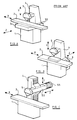
- Hitherto surface grinding machines have been currently or traditionally of the forms diagrammatically shown in Figures A. B and C of the accompanying drawings. These machines basically comprise a bed 1; a work table 2 horizontally movable or reciprocatable along an X axis generally on the bed 1; usually a saddle or backslide 3 ( Figures A and B) horizontally movable on the bed along a traversing Z axis, and a column 4 upstanding from the bed 1 or backslide 3 ( Figure B) and carrying a wheelhead 5 for at least vertical feeding/retraction movement along a Y-axis in relation to a workpiece on the table 2.
- the wheelhead 5 is fed downwardly on the Y-axis onto a workpiece or component to be ground on the work table 2.
- the bed 1 slidably carries along the Z axis the saddle 3 which in turn carries the table 2 slidable thereon for reciprocation along the X axis.
- the column 4 upstanding from the bed 1 carries the wheelhead 5, vertically movable along the Y axis.
- the moving head machine shown in Figure C tends to be a larger size of machine with a wide worktable 2 and wherein the mass to be transversed (Z axis) is minimised, i.e. to only the mass of the wheelhead 5 with its carrier 50 and driving motor 55. (This is considerably less than the mass of a saddle 3 and table 2 with a workpiece thereon and also much less than that of a backslide 3 carrying a column 4 and wheelhead 5).
- the machine can have a long bed 1 to fully or largely support the table 2, the wheelhead unit 5, 50, 55 is carried by a relatively tall and slender column 4 and the moveable wheelhead 5 has a variable overhang which gives rise to variations in geometric accuracy.
- the document US-A- 3 481 082 relates to a machine tool which, too, is provided with a column. On the column, therein is mounted a cross-slide carrying the tool.
- the work table which is vertically adjustable, is in front of the column.
- a grinding or like machine tool in which the front face of a generally rectangular machine bed carries a work table for Y axis vertical travelling movement or adjustment and in which the top of the bed slidably carries a saddle which in turn slidably carries at least one grinding wheel head or like machining head for movement at right angles to the movement of the saddle whereby the or each grinding wheel or like machining head is positioned over the work table and is operated for X axis reciprocating or uni-directional longitudinal movement and Z axis traversing movement in relation to the work table and a workpiece or workpieces when placed thereon, by relative sliding movements of the saddle and wheel or like machining head or heads on the top of the machine bed.
- the saddle is slidably carried on the machine bed for Z axis traversing movement at right angles to the work table and the or each wheel or like machining head is slidably carried by the saddle for X axis longitudinal or reciprocating movement parallel with and over the work table.
- the work table is fixedly carried by a support member or knee mounted for vertical travelling or sliding movement only on the machine bed. Thus the table remains fixed against longitudinal or reciprocating movement relative to the machine bed.
- a saddle 13 is mounted by slideways 130 on the top of the bed 10 for traversing Z axis movement towards and away from the table 12 and at right angles to it.
- a carrier slide 16 mounted on slideways 160 on the saddle 13 for X axis movement fixedly carries at right angles to it a wheelhead 15 together with an associated carrier 150 and driving motor 155 so that the wheelhead 15 over hangs the table 2.
- the slide 16 is movable on the saddle 13 for X axis movement along slideways 160 parallel with the table 12 and thus for longitudinal or reciprocating movement of the wheelhead 15 and grinding wheel 17 over the table 12 for grinding a workpiece thereon.
- the knee 11, saddle 13 and wheelhead slide 16 are respectively operated by ball screws 111, 131 and 161 each driven by a separate suitable electric motor, e.g as shown at 165 via a toothed belt drive 166 in the case of the slide ballscrew 161.
- the belt drive 166 is shown accommodated in a housing 167.
- Parallel raised portions 122 of the table 12 define the workpiece mounting area whilst end portions 123 receive any necessary equipment for the purpose of the grinding operation such as a wheel dresser.
- the wheelhead 15 When in operation the wheelhead 15 is usually reciprocated for pendulum grinding or fed slowly for creep feed grinding along the X axis by its slide 16 on the saddle 13. Grinding cut is set by raising the knee 11, table 12 and workpiece along the Y axis and traverse of the wheelhead 15 across the workpiece as grinding proceeds is effected by appropriate movement of the saddle 13 along the Z axis. On completion of the grinding operation the table 12 is lowered for enabling the ground workpiece to be readily removed clear of the grinding wheel 17.
- Coolant from the wheelhead mounted nozzle 18 drains from the table 12 into a trough 20 fixed underneath the table 12 and from thence to a coolant reservoir tank 21.
- Correlated operation of the knee 11, saddle 13 and wheelhead slide 16 is controlled such as by CNC control for performing a required grinding operation or operations which typically may include heavy rough cutting stock removal from the workpiece by longitudinal creep grinding feed of the wheelhead 15 followed by reciprocation of the latter for finish grinding, appropriate grinding wheels 17 being used.
- the saddle 13 may be movable or reciprocatable on the bed 10 along the X axis and the wheelhead assembly 15, 150 and 155 is then carried by the saddle 13 for such movement therewith and for relative traversing movement along the Z axis.
- the X axis reciprocatable mass of the wheelhead assembly 15, 150 and 155 and saddle 13 would be considerably greater than that of the wheelhead assembly 15, 150 and 155 and slide 16 of the preferred arrangement described above with reference to Figures 1 and 2.
- one grinding wheel 17 may be operated for rough cutting stock removal from a workpiece by longitudinal creep grinding and the other for fine finish reciprocating grinding, appropriate types of wheel being employed. As a result the compromise of a single wheel is avoided so that improved component quality can be obtained.
- each wheel 17 is driven by a separate driving motor 155 so that the individual wheels can be run at their optimum speeds whilst separate coolant supply can be applied to each wheel to suit its mode of operation.
- the two wheels 17 may be contra rotatable.
- vertical spindle grinding can be provided either singly or in a twin tandem or independent arrangement similar to that described above and with the same practical advantages.
- the grinding wheel or disc 117 is rotated about its vertical axis on its wheel head 115 by its driving motor 155 also shown mounted about a vertical axis. Again twin wheels or discs 117 would be separately motor driven.
- a wheel dresser can be mounted on each end part of the work table 12 one to each wheel 17 or disc 117 and again the mode of dressing can be optimised to the grinding operation and wheel type.
- any twin combination of horizontal and vertical grinding wheel spindles can be employed and in some cases more than two spindles and wheels may be used in a multi-spindle arrangement i.e. according to the nature of the workpiece or workpieces to be ground.
Landscapes
- Engineering & Computer Science (AREA)
- Mechanical Engineering (AREA)
- Grinding Of Cylindrical And Plane Surfaces (AREA)
- Constituent Portions Of Griding Lathes, Driving, Sensing And Control (AREA)
Description
- Figure 1
- is a diagrammatic front perspective view of the machine;
- Figure 2
- is a more detailed front perspective view;
- Figure 3
- is a detail side elevation of the wheel head assembly;
- Figure 4
- is a detail perspective view of an indexing fixture development;
- Figures 5 and 6
- are diagrammatic front and side elevations respectively of a twin wheel head development of the machine;
- Figures 7 and 8
- are similar views of a further twin wheel head arrangement, and
- Figures 9 and 10
- are similar views of a vertical axis wheel head arrangement.
Claims (15)
- A grinding or like machine tool for reciprocating or uni-directional surface or similar grinding or machining of a workpiece or workpieces and in which a grinding wheel head or like machining head (15) is slidably supported on the machine bed (10) for operative movement over a work table (12) mounted on the machine bed (10); is characterised by the machine bed (10) consisting of a generally rectangular body without a column and having support means (11) directly and slidably mounted (110) on the front face thereof so as to extend forwardly therefrom and operable (111) for vertical sliding movement or adjustment relative to said front face of the machine bed (10); said support means (11) carrying the work table (12) for corresponding Y axis vertical movement or adjustment only of said work table (12) i.e. for upward feeding movement towards at least one grinding wheel or like machining head (15, 115) or downward withdrawal movement therefrom; and in which the top of the machine bed (10) carries for operable (131) direct horizontal sliding movement (130) thereon a saddle (13) which, in turn, carries for operable (161) direct horizontal sliding movement (160) thereon the or each said grinding wheel or like machining head (15,115) and direct motor drive (155) thereto for said sliding movement (160) at right angles to the sliding movement (130) of the saddle (13) on the top of the machine bed (10) whereby the or each said grinding wheel or like machining head (15, 115) is positioned over the work table (12) and is operable for horizontal X axis reciprocating or uni-directional longitudinal movement and horizontal Z axis traversing movement as required in horizontal planes only in relation to the work table (12) and a workpiece or workpieces when placed thereon by said relative horizontal movements of the saddle (13) and grinding wheel or like machining head or heads (15, 115) thereon on the top of the machine bed (10).
- A grinding or like machine tool according to claim 1 wherein the support means (11) which carries the work table (12) for "Y" axis vertical sliding movement or adjustment only is such that the work table (12) remains fixed against any horizontal reciprocating or uni-directional longitudinal movement relative to the machine bed (10).
- A grinding or like machine tool according to claim 1 or 2 wherein the support means (11) which carries the work table (12) is in the form of a knee extending forwardly from the front face of the machine bed (10) for said vertical sliding movement or adjustment thereon.
- A grinding or like machine tool according to any of the preceding claims wherein the or each grinding wheel or like machining head (15, 115) is slidably carried by the saddle (13) by means of a carrier saddle (16).
- A grinding or like machine tool according to any of claims 1 to 4 wherein the saddle (13) is slidably carried on the top of the machine bed (10) for Z axis traversing movement thereon at right angles to the work table (12), and the or each wheel or like machining head (15, 115) is slidably carried by the saddle (13) for X axis reciprocating or uni-directional longitudinal movement parallel with and over the work table (12) and also Z axis traversing movement thereover by the saddle (13).
- A grinding or like machine tool according to any of claims 1 to 4 wherein the saddle (13) is slidably or similarly carried on the top of the machine bed (10) for X axis reciprocating or uni-directional longitudinal movement thereon parallel with the work table (12), and the or each wheel or like machining head (15, 115) is slidably carried by the saddle (13) for Z axis traversing movement at right angles to and over the work table (12) and also X axis reciprocating or uni-directional longitudinal movement thereover by the saddle (13).
- A grinding or like machine tool according to any of the preceding claims wherein slidable support means (11, 110) for Y axis vertical movement or adjustment of the work table (12) and slidable support (130) of the saddle (13) and slidable support (160) of the or each grinding wheel or like machining head (15, 115) on the saddle (13), or at least one or more of them is or are arranged or supported so as to resist couples on said slidable support or supports due to inertial or other force in order to maintain geometric accuracy.
- A grinding or like machine tool according to claim 7 wherein the or each grinding wheel or like machining head (15, 115) and its direct motor drive (155) and a carrier (150) for them are of balanced constructing whereby substantially no couple is applied to their slidable support (156, 160) on the saddle (13).
- A grinding or like machine tool according to any of the preceding claims wherein a fixed receptacle or trough (20) is provided under the work table (12) and from the machine bed (10) for receiving coolant draining from the work table (12) in a controlled manner, i.e. against swilling or surging of the coolant on the table (12) and in the receptacle or trough (20).
- A grinding or like machine tool according to any of the preceding claims wherein an indexing support or table (60) is provided mountable on the work table (12) and provides two or more fixtures (61, 62) each for the positioning of one or more work pieces for grinding or machining so that while such grinding or machining is taking place on one fixture (61) any previously ground or machined work piece or work pieces can be unloaded from another fixture (62) at an unloading/loading position which, after work piece loading or re-loading thereat, is indexed to a grinding or machining position so that a virtually continuous grinding or machining operation can be provided.
- A grinding or like machine tool according to claim 10 wherein the indexing support or table (60) is rotatably mountable on the work table (12) for indexing movement.
- A grinding or like machine tool according to any of the preceding claims wherein the saddle (13) slidably carries at least two grinding wheel heads or like machining heads (15, 115) for sliding movement at right angles to the movement of the saddle (13) and wherein said grinding wheel or like machining heads (15, 115) are either slidably movable together in tandem on the saddle (13) or are independently movable thereon and over the work table (12).
- A grinding or like machine tool according to any of the preceding claims wherein the or each grinding wheel or like machining head (15, 115) is arranged to carry a grinding wheel (117) or like tool for rotation about a substantially vertical axis over the work table (12).
- A grinding or like machine tool according to claim 12 or 13 wherein the grinding wheel or like machining heads (15, 115) are arranged to provide support for a combination of different types of grinding wheels (17, 117) or like tools carried for rotation about substantially horizontal and substantially vertical axes over the work table (12).
- A grinding or like machine tool according to claim 12, 13 or 14 wherein each grinding wheel or like machining head (15, 115) is separately motor driven (155).
Applications Claiming Priority (3)
| Application Number | Priority Date | Filing Date | Title |
|---|---|---|---|
| GBGB9705134.6A GB9705134D0 (en) | 1997-03-12 | 1997-03-12 | Grinding or like machine tool |
| GB9705134 | 1997-03-12 | ||
| PCT/GB1998/000734 WO1998040191A1 (en) | 1997-03-12 | 1998-03-11 | Grinding or like machine tool |
Publications (2)
| Publication Number | Publication Date |
|---|---|
| EP0981419A1 EP0981419A1 (en) | 2000-03-01 |
| EP0981419B1 true EP0981419B1 (en) | 2002-02-06 |
Family
ID=10809128
Family Applications (1)
| Application Number | Title | Priority Date | Filing Date |
|---|---|---|---|
| EP98909605A Expired - Lifetime EP0981419B1 (en) | 1997-03-12 | 1998-03-11 | Grinding or like machine tool |
Country Status (5)
| Country | Link |
|---|---|
| EP (1) | EP0981419B1 (en) |
| AU (1) | AU6409498A (en) |
| DE (1) | DE69803763T2 (en) |
| GB (1) | GB9705134D0 (en) |
| WO (1) | WO1998040191A1 (en) |
Cited By (3)
| Publication number | Priority date | Publication date | Assignee | Title |
|---|---|---|---|---|
| EP1757405A1 (en) | 2005-08-24 | 2007-02-28 | Blohm Maschinenbau GmbH | Method for machining of workpieces with curved surfaces, in particular for turbine blades, machine tool and programming system. |
| CN103350374A (en) * | 2013-06-26 | 2013-10-16 | 大丰市远大机床有限公司 | Numerically controlled surface grinding machine |
| CN112157511A (en) * | 2020-09-29 | 2021-01-01 | 杭州恒逍家具有限公司 | Furniture intelligent manufacturing device for polishing wooden boards |
Families Citing this family (6)
| Publication number | Priority date | Publication date | Assignee | Title |
|---|---|---|---|---|
| DE19902137C1 (en) * | 1999-01-20 | 2000-06-29 | Ilg Gmbh | Machine tool for grinding workpieces has grinder and workpiece holder movable on machine tool stand in different directions parallel to vertical wall to engage workpiece and grinder |
| ES2168058B1 (en) * | 2000-04-07 | 2004-02-16 | Danobat | DOUBLE MOBILE COLUMN RECTIFIER WITH SIMULTANEOUS RECTIFICATE WITH TWO SPRINGS. |
| CN100460145C (en) * | 2005-02-04 | 2009-02-11 | 威海华东数控股份有限公司 | The structure of the machine tool |
| CN102126168A (en) * | 2010-12-30 | 2011-07-20 | 大丰市远大机床有限公司 | Small-sized numerical control surface grinding machine |
| CN105397503B (en) * | 2015-12-10 | 2018-09-14 | 佛山欧亚特机械设备有限公司 | A kind of cantilevered shape extrusion device |
| CN118417982A (en) * | 2024-07-03 | 2024-08-02 | 潍坊宝润机械有限公司 | Engine parts deburring device and method |
Family Cites Families (3)
| Publication number | Priority date | Publication date | Assignee | Title |
|---|---|---|---|---|
| US2927405A (en) * | 1957-11-21 | 1960-03-08 | Guzowski Frank | Contour grinder |
| US3481082A (en) * | 1967-09-25 | 1969-12-02 | Oliver Instr Co | Cutter grinder with fluid cushion work support |
| US4114015A (en) * | 1974-05-27 | 1978-09-12 | Vladimir Sergeevich Vasiliev | Electric discharge machine with a program copier and a tool support head carried by a longitudinally and transversely driven carriage |
-
1997
- 1997-03-12 GB GBGB9705134.6A patent/GB9705134D0/en active Pending
-
1998
- 1998-03-11 WO PCT/GB1998/000734 patent/WO1998040191A1/en not_active Ceased
- 1998-03-11 EP EP98909605A patent/EP0981419B1/en not_active Expired - Lifetime
- 1998-03-11 AU AU64094/98A patent/AU6409498A/en not_active Abandoned
- 1998-03-11 DE DE69803763T patent/DE69803763T2/en not_active Expired - Fee Related
Cited By (4)
| Publication number | Priority date | Publication date | Assignee | Title |
|---|---|---|---|---|
| EP1757405A1 (en) | 2005-08-24 | 2007-02-28 | Blohm Maschinenbau GmbH | Method for machining of workpieces with curved surfaces, in particular for turbine blades, machine tool and programming system. |
| CN103350374A (en) * | 2013-06-26 | 2013-10-16 | 大丰市远大机床有限公司 | Numerically controlled surface grinding machine |
| CN112157511A (en) * | 2020-09-29 | 2021-01-01 | 杭州恒逍家具有限公司 | Furniture intelligent manufacturing device for polishing wooden boards |
| CN112157511B (en) * | 2020-09-29 | 2021-11-23 | 山东凯迪威家具有限公司 | Furniture intelligent manufacturing device for polishing wooden boards |
Also Published As
| Publication number | Publication date |
|---|---|
| GB9705134D0 (en) | 1997-04-30 |
| EP0981419A1 (en) | 2000-03-01 |
| DE69803763T2 (en) | 2002-09-05 |
| AU6409498A (en) | 1998-09-29 |
| WO1998040191A1 (en) | 1998-09-17 |
| DE69803763D1 (en) | 2002-03-21 |
Similar Documents
| Publication | Publication Date | Title |
|---|---|---|
| US6796012B2 (en) | Milling machine for carrying out milling and turning operations on rod material | |
| CN106736911B (en) | Centerless grinding machine | |
| JP5562446B2 (en) | Machine Tools | |
| CN208929241U (en) | The automatic lathe gang feed tool rack of mountable multiple cutters | |
| CN109202560A (en) | Automatic change numerically control grinder | |
| EP0981419A1 (en) | Grinding or like machine tool | |
| CN213858549U (en) | Grinding head mechanism for numerical control grinding machine | |
| CN211804803U (en) | Vertical and horizontal combined machining equipment | |
| US4993138A (en) | Tool milling machine or the like type complex processing machine | |
| CN215150636U (en) | Cantilever type tapping machine | |
| CN114789381B (en) | Automatic double-standard trend type plane grinding ball track grinding machine for double-track horizontal ball milling | |
| KR20100118068A (en) | shelf | |
| CN110549195A (en) | Metal plate trimming machine tool equipment | |
| CN110936163B (en) | Cogging method for machining gear by numerical control machine tool | |
| CN113770734B (en) | End surface concave arc turning and milling composite machine tool | |
| CN210968152U (en) | Automatic device for grinding silicon rod plane and chamfer | |
| CN209919013U (en) | Disc saw blade gear grinding machine | |
| CN216463479U (en) | High-speed grinding machine | |
| CN219234905U (en) | Grinding machine with pneumatic adjusting table for machining mechanical parts | |
| CN213858078U (en) | Novel base for vertical and horizontal combined machining center | |
| JP2547990B2 (en) | Automatic lathe | |
| JPH0137851Y2 (en) | ||
| RU2089383C1 (en) | Bench-type multifunction machine | |
| RU2022758C1 (en) | Universal machine | |
| CN215546660U (en) | Grinding device of numerical control laser machine tool |
Legal Events
| Date | Code | Title | Description |
|---|---|---|---|
| PUAI | Public reference made under article 153(3) epc to a published international application that has entered the european phase |
Free format text: ORIGINAL CODE: 0009012 |
|
| 17P | Request for examination filed |
Effective date: 19990809 |
|
| AK | Designated contracting states |
Kind code of ref document: A1 Designated state(s): CH DE GB LI |
|
| GRAG | Despatch of communication of intention to grant |
Free format text: ORIGINAL CODE: EPIDOS AGRA |
|
| 17Q | First examination report despatched |
Effective date: 20010530 |
|
| GRAG | Despatch of communication of intention to grant |
Free format text: ORIGINAL CODE: EPIDOS AGRA |
|
| GRAH | Despatch of communication of intention to grant a patent |
Free format text: ORIGINAL CODE: EPIDOS IGRA |
|
| GRAH | Despatch of communication of intention to grant a patent |
Free format text: ORIGINAL CODE: EPIDOS IGRA |
|
| GRAA | (expected) grant |
Free format text: ORIGINAL CODE: 0009210 |
|
| REG | Reference to a national code |
Ref country code: GB Ref legal event code: IF02 |
|
| AK | Designated contracting states |
Kind code of ref document: B1 Designated state(s): CH DE GB LI |
|
| REG | Reference to a national code |
Ref country code: CH Ref legal event code: NV Representative=s name: HEPP, WENGER & RYFFEL AG Ref country code: CH Ref legal event code: EP |
|
| REF | Corresponds to: |
Ref document number: 69803763 Country of ref document: DE Date of ref document: 20020321 |
|
| PLBE | No opposition filed within time limit |
Free format text: ORIGINAL CODE: 0009261 |
|
| STAA | Information on the status of an ep patent application or granted ep patent |
Free format text: STATUS: NO OPPOSITION FILED WITHIN TIME LIMIT |
|
| 26N | No opposition filed |
Effective date: 20021107 |
|
| PGFP | Annual fee paid to national office [announced via postgrant information from national office to epo] |
Ref country code: DE Payment date: 20050304 Year of fee payment: 8 |
|
| PGFP | Annual fee paid to national office [announced via postgrant information from national office to epo] |
Ref country code: GB Payment date: 20050309 Year of fee payment: 8 |
|
| PGFP | Annual fee paid to national office [announced via postgrant information from national office to epo] |
Ref country code: CH Payment date: 20050316 Year of fee payment: 8 |
|
| PG25 | Lapsed in a contracting state [announced via postgrant information from national office to epo] |
Ref country code: GB Free format text: LAPSE BECAUSE OF NON-PAYMENT OF DUE FEES Effective date: 20060311 |
|
| PG25 | Lapsed in a contracting state [announced via postgrant information from national office to epo] |
Ref country code: LI Free format text: LAPSE BECAUSE OF NON-PAYMENT OF DUE FEES Effective date: 20060331 Ref country code: CH Free format text: LAPSE BECAUSE OF NON-PAYMENT OF DUE FEES Effective date: 20060331 |
|
| PG25 | Lapsed in a contracting state [announced via postgrant information from national office to epo] |
Ref country code: DE Free format text: LAPSE BECAUSE OF NON-PAYMENT OF DUE FEES Effective date: 20061003 |
|
| REG | Reference to a national code |
Ref country code: CH Ref legal event code: PL |
|
| GBPC | Gb: european patent ceased through non-payment of renewal fee |
Effective date: 20060311 |