EP0980772A2 - Fahrzeugaufhängungssystem - Google Patents
Fahrzeugaufhängungssystem Download PDFInfo
- Publication number
- EP0980772A2 EP0980772A2 EP99650074A EP99650074A EP0980772A2 EP 0980772 A2 EP0980772 A2 EP 0980772A2 EP 99650074 A EP99650074 A EP 99650074A EP 99650074 A EP99650074 A EP 99650074A EP 0980772 A2 EP0980772 A2 EP 0980772A2
- Authority
- EP
- European Patent Office
- Prior art keywords
- fluid
- vehicle
- hydraulic
- suspension system
- pump
- Prior art date
- Legal status (The legal status is an assumption and is not a legal conclusion. Google has not performed a legal analysis and makes no representation as to the accuracy of the status listed.)
- Granted
Links
- 239000000725 suspension Substances 0.000 title claims abstract description 53
- 239000012530 fluid Substances 0.000 claims abstract description 99
- 238000013016 damping Methods 0.000 claims abstract description 12
- 230000001105 regulatory effect Effects 0.000 claims abstract description 3
- 230000001133 acceleration Effects 0.000 claims description 17
- 238000006073 displacement reaction Methods 0.000 claims description 11
- 230000000295 complement effect Effects 0.000 claims description 6
- 238000010276 construction Methods 0.000 claims description 3
- 239000000654 additive Substances 0.000 claims description 2
- 230000000996 additive effect Effects 0.000 claims description 2
- 238000005086 pumping Methods 0.000 abstract 1
- 238000004891 communication Methods 0.000 description 2
- 230000007423 decrease Effects 0.000 description 2
- 230000003247 decreasing effect Effects 0.000 description 2
- 238000005259 measurement Methods 0.000 description 2
- 230000010355 oscillation Effects 0.000 description 2
- 230000003068 static effect Effects 0.000 description 2
- 230000006835 compression Effects 0.000 description 1
- 238000007906 compression Methods 0.000 description 1
- 238000001514 detection method Methods 0.000 description 1
- 238000004519 manufacturing process Methods 0.000 description 1
- 239000012528 membrane Substances 0.000 description 1
Images


Classifications
-
- B—PERFORMING OPERATIONS; TRANSPORTING
- B60—VEHICLES IN GENERAL
- B60G—VEHICLE SUSPENSION ARRANGEMENTS
- B60G21/00—Interconnection systems for two or more resiliently-suspended wheels, e.g. for stabilising a vehicle body with respect to acceleration, deceleration or centrifugal forces
- B60G21/10—Interconnection systems for two or more resiliently-suspended wheels, e.g. for stabilising a vehicle body with respect to acceleration, deceleration or centrifugal forces not permanently interconnected, e.g. operative only on acceleration, only on deceleration or only at off-straight position of steering
-
- B—PERFORMING OPERATIONS; TRANSPORTING
- B60—VEHICLES IN GENERAL
- B60G—VEHICLE SUSPENSION ARRANGEMENTS
- B60G17/00—Resilient suspensions having means for adjusting the spring or vibration-damper characteristics, for regulating the distance between a supporting surface and a sprung part of vehicle or for locking suspension during use to meet varying vehicular or surface conditions, e.g. due to speed or load
- B60G17/015—Resilient suspensions having means for adjusting the spring or vibration-damper characteristics, for regulating the distance between a supporting surface and a sprung part of vehicle or for locking suspension during use to meet varying vehicular or surface conditions, e.g. due to speed or load the regulating means comprising electric or electronic elements
- B60G17/016—Resilient suspensions having means for adjusting the spring or vibration-damper characteristics, for regulating the distance between a supporting surface and a sprung part of vehicle or for locking suspension during use to meet varying vehicular or surface conditions, e.g. due to speed or load the regulating means comprising electric or electronic elements characterised by their responsiveness, when the vehicle is travelling, to specific motion, a specific condition, or driver input
- B60G17/0162—Resilient suspensions having means for adjusting the spring or vibration-damper characteristics, for regulating the distance between a supporting surface and a sprung part of vehicle or for locking suspension during use to meet varying vehicular or surface conditions, e.g. due to speed or load the regulating means comprising electric or electronic elements characterised by their responsiveness, when the vehicle is travelling, to specific motion, a specific condition, or driver input mainly during a motion involving steering operation, e.g. cornering, overtaking
-
- B—PERFORMING OPERATIONS; TRANSPORTING
- B60—VEHICLES IN GENERAL
- B60G—VEHICLE SUSPENSION ARRANGEMENTS
- B60G17/00—Resilient suspensions having means for adjusting the spring or vibration-damper characteristics, for regulating the distance between a supporting surface and a sprung part of vehicle or for locking suspension during use to meet varying vehicular or surface conditions, e.g. due to speed or load
- B60G17/02—Spring characteristics, e.g. mechanical springs and mechanical adjusting means
- B60G17/027—Mechanical springs regulated by fluid means
- B60G17/0272—Mechanical springs regulated by fluid means the mechanical spring being a coil spring
-
- B—PERFORMING OPERATIONS; TRANSPORTING
- B60—VEHICLES IN GENERAL
- B60G—VEHICLE SUSPENSION ARRANGEMENTS
- B60G21/00—Interconnection systems for two or more resiliently-suspended wheels, e.g. for stabilising a vehicle body with respect to acceleration, deceleration or centrifugal forces
- B60G21/02—Interconnection systems for two or more resiliently-suspended wheels, e.g. for stabilising a vehicle body with respect to acceleration, deceleration or centrifugal forces permanently interconnected
- B60G21/06—Interconnection systems for two or more resiliently-suspended wheels, e.g. for stabilising a vehicle body with respect to acceleration, deceleration or centrifugal forces permanently interconnected fluid
-
- B—PERFORMING OPERATIONS; TRANSPORTING
- B60—VEHICLES IN GENERAL
- B60G—VEHICLE SUSPENSION ARRANGEMENTS
- B60G2202/00—Indexing codes relating to the type of spring, damper or actuator
- B60G2202/30—Spring/Damper and/or actuator Units
- B60G2202/32—The spring being in series with the damper and/or actuator
-
- B—PERFORMING OPERATIONS; TRANSPORTING
- B60—VEHICLES IN GENERAL
- B60G—VEHICLE SUSPENSION ARRANGEMENTS
- B60G2202/00—Indexing codes relating to the type of spring, damper or actuator
- B60G2202/40—Type of actuator
- B60G2202/41—Fluid actuator
- B60G2202/413—Hydraulic actuator
-
- B—PERFORMING OPERATIONS; TRANSPORTING
- B60—VEHICLES IN GENERAL
- B60G—VEHICLE SUSPENSION ARRANGEMENTS
- B60G2202/00—Indexing codes relating to the type of spring, damper or actuator
- B60G2202/40—Type of actuator
- B60G2202/41—Fluid actuator
- B60G2202/414—Fluid actuator using electrohydraulic valves
-
- B—PERFORMING OPERATIONS; TRANSPORTING
- B60—VEHICLES IN GENERAL
- B60G—VEHICLE SUSPENSION ARRANGEMENTS
- B60G2204/00—Indexing codes related to suspensions per se or to auxiliary parts
- B60G2204/80—Interactive suspensions; arrangement affecting more than one suspension unit
- B60G2204/81—Interactive suspensions; arrangement affecting more than one suspension unit front and rear unit
- B60G2204/8102—Interactive suspensions; arrangement affecting more than one suspension unit front and rear unit diagonally arranged
-
- B—PERFORMING OPERATIONS; TRANSPORTING
- B60—VEHICLES IN GENERAL
- B60G—VEHICLE SUSPENSION ARRANGEMENTS
- B60G2204/00—Indexing codes related to suspensions per se or to auxiliary parts
- B60G2204/80—Interactive suspensions; arrangement affecting more than one suspension unit
- B60G2204/82—Interactive suspensions; arrangement affecting more than one suspension unit left and right unit on same axle
-
- B—PERFORMING OPERATIONS; TRANSPORTING
- B60—VEHICLES IN GENERAL
- B60G—VEHICLE SUSPENSION ARRANGEMENTS
- B60G2204/00—Indexing codes related to suspensions per se or to auxiliary parts
- B60G2204/80—Interactive suspensions; arrangement affecting more than one suspension unit
- B60G2204/83—Type of interconnection
- B60G2204/8304—Type of interconnection using a fluid
-
- B—PERFORMING OPERATIONS; TRANSPORTING
- B60—VEHICLES IN GENERAL
- B60G—VEHICLE SUSPENSION ARRANGEMENTS
- B60G2500/00—Indexing codes relating to the regulated action or device
- B60G2500/10—Damping action or damper
-
- B—PERFORMING OPERATIONS; TRANSPORTING
- B60—VEHICLES IN GENERAL
- B60G—VEHICLE SUSPENSION ARRANGEMENTS
- B60G2500/00—Indexing codes relating to the regulated action or device
- B60G2500/20—Spring action or springs
Definitions
- This invention relates to a vehicle suspension system.
- the use of devices such as anti-roll bars degrade the performance of the suspension system.
- vehicles designed for good off-road mobility sometimes employ independent suspension with a long wheel travel capability.
- the use of an anti-roll bar increases the suspension stiffness, even in the absence of body roll, when the wheels on opposite sides of the vehicle are moving in different directions in response to the terrain, thus reducing the independence of the wheel movements.
- Patent Specification No. US 4693493 describes a system for vehicle body roll control using steering angle detection.
- British Patent Specification No. GB 2313346 there is described a pneumatic anti-roll system for vehicles.
- An active suspension system typically uses a power source external to the suspension system to drive an hydraulic pump that transfers fluid from a reservoir through a servo valve into a pressurised part of the suspension system. Because the pump must raise the pressure of the hydraulic fluid from reservoir pressure to system pressure, and because of the metering action of the servo valves, such systems often involve a significant power loss. Such systems are also relatively complex and expensive.
- the present invention is directed towards overcoming these problems.
- a suspension system for a pair of spaced-apart wheels on a vehicle comprising:-
- the invention provides a roll and/or pitch control suspension system for a vehicle in which high pressure hydraulic fluid is pumped directly between hydraulic actuators in a controlled manner to counteract sensed roll and/or pitch of the vehicle.
- This arrangement advantageously helps minimise the power requirement and provides a relatively simple system with a view to minimising manufacturing cost and providing reliability in operation.
- the spring means is an hydraulic accumulator connected to the hydraulic actuator fluid chamber by a fluid line and the damping means is a flow restrictor mounted in the fluid line between the fluid chamber and the accumulator.
- the spring means is a mechanical spring and the damping means is a mechanical damper.
- the spring means comprises a main piston incorporating a gas chamber and an oil chamber separated by a separator piston, said main piston forming a piston of the hydraulic actuator which slides within a complementary actuator cylinder and the damping means is a flow restrictor between the oil chamber in the main piston and the fluid chamber in the actuator cylinder.
- the hydraulic actuators are mounted at wheels on opposite sides of the vehicle. In a further embodiment, the hydraulic actuators are mounted at wheels on a common axle of the vehicle. In another embodiment, the hydraulic actuators are mounted at wheels which are longitudinally spaced-apart on the vehicle.
- the hydraulic actuator is of two part construction comprising a piston slidably mounted in a complementary cylinder to provide the variable volume hydraulic fluid chamber, one part being attached to the wheel and the other part being attached to the vehicle chassis.
- one of said parts has a spring and/or damper mounted between said part and the wheel or chassis.
- means is provided for adjustment of the quantity of gas within the accumulator or gas chamber.
- means is provided for the gradual adjustment of the quantity of hydraulic fluid in the system.
- control valve is a servo valve.
- means may be provided for adjusting the quantity of hydraulic fluid in each accumulator.
- each flow restrictor is adjustable.
- the sensing means is operable to sense one or more of the vehicle attitude parameters selected from the group: lateral acceleration, roll angle, roll rate, braking, steering angle, pitch angle or pitch rate.
- the sensing means includes means for sensing the vehicle speed.
- the sensing means includes means for sensing the longitudinal acceleration of the vehicle.
- the sensing means includes means for sensing wheel displacement relative to the chassis.
- each hydraulic actuator comprises a forward hydraulic actuator and a rearward hydraulic actuator mounted on a forward axle and a rearward axle on the same side of the vehicle, the fluid chambers of the actuators on each side of the vehicle communicating with a common hydraulic accumulator.
- each suspension system having the first and second hydraulic actuator mounted at longitudinally spaced-apart wheels on opposite sides of the vehicle.
- the pair of suspension systems may be interconnected by an equalising valve connected between the fluid transfer lines of the different systems, said equalising valve being operable to allow the slow bleed of hydraulic fluid between the systems in response to a sensed difference in averaged extension of hydraulic actuators in the two systems.
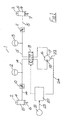
- Fig. 1 there is illustrated a suspension system according to the invention for a vehicle, the suspension system indicated generally by the reference numeral 1.
- FIG. 1 shows, on the left side of a vehicle, a hydraulic actuator 2 and on the right side of the vehicle an associated hydraulic actuator 3.
- Each hydraulic actuator 2, 3 comprises a cylinder 4, 5 and associated piston 6, 7.
- Either one of the cylinder 4, 5 or the piston 6,7 is connected directly or indirectly to the vehicle chassis while the complementary cylinder 4, 5 or piston 6, 7 is connected directly or indirectly to a road wheel of the vehicle so that, when relative movement occurs between the wheel and the vehicle chassis, hydraulic fluid is displaced from a variable volume fluid chamber 8, 9 of the hydraulic actuator 2, 3 defined by a cylinder 4, 5 and associated piston 6, 7 through a flow restrictor such as an orifice 10, 11 to or from an accumulator 12, 13 associated with each chamber 8, 9 and in fluid communication therewith via fluid transfer lines 14, 15.
- a flow restrictor such as an orifice 10, 11 to or from an accumulator 12, 13 associated with each chamber 8, 9 and in fluid communication therewith via fluid transfer lines 14, 15.
- the accumulator 12, 13 accepts fluid flow from the chamber 8, 9 with a rise in pressure and thus acts as a fluid spring. This may be accomplished by known means such as compression of a piston or membrane against a gas or spring.
- a flow restrictor orifice 10, 11 Mounted on the fluid transfer line 14, 15 between the chamber 8, 9 and the accumulator 12, 13 is a flow restrictor orifice 10, 11 which provides damping to the suspension system.
- a pump 16 communicates between the chambers 8, 9 of both hydraulic actuators 2, 3 through a control valve 19 which is operable to isolate both chambers 8, 9 from each other and from the pump 16 (as shown in Fig. 1) or to selectively connect one chamber 8, 9 with an inlet 17 of the pump 16 and at the same time connect the other chamber 8, 9 with an outlet 18 of the pump 16.
- Pump 16 may preferably be a fixed displacement pump in which the volume of fluid displaced by the pump 16 is related mainly to the number of revolutions of the pump drive shaft. Alternatively, it may be any other type of pump.
- the pump 16 has an inlet 17 and an outlet 18. Pump 16 displaces fluid through a three-position control valve 19. When the control valve 19 is centred as is shown in Fig. 1, it allows the fluid to circulate through it from the pump outlet 18 to the pump inlet 17 with minimal pressure drop. When the control valve 19 is displaced to the right (in the drawing, Fig.
- the pump 16 displaces fluid from the left-hand accumulator 12 to the right hand accumulator 13 through fluid lines 14, 15, thereby decreasing the suspension force on the left side of the vehicle and increasing the force on the right side of the vehicle.
- the pump 16 is a fixed displacement pump, the amount of fluid displaced will be approximately proportional to the number of revolutions of the pump 16 which occur while control valve 19 is displaced from its centre position. It is intended to actuate the control valve 19 in this way when the vehicle is steered to the left or alternatively in response to increasing lateral acceleration and roll angle induced in a left-hand turn of the vehicle. If the lateral acceleration becomes approximately constant, control valve 19 is centred.
- control valve 19 When the acceleration decreases, control valve 19 is displaced to the left in order to return fluid from the right to the left suspension system. During a vehicle right hand turn, the opposite sequence of operation occurs. Thereby the net fluid transferred is varied in accordance with a desired relationship to the lateral acceleration.
- a sensor 21 may be any known means of sensing at least one vehicle attitude parameter such as lateral acceleration, roll angle or roll rate of the vehicle for example. Alternatively, sensor 21 may measure steering wheel angle or represent multiple sensors associated with a number of parameters.
- a controller 20 has as inputs the measurement from sensor 21 or from multiple sensors 21, said attitude parameter sensor inputs being indicated at 23, the position of control valve 19 at any instant, and a measure of the fluid flow through the pump 16, which in the case of a fixed displacement pump, may be a count of the number of revolutions of the pump 16 using a count sensor 22 connected to the controller 20 by communication line 24. This information may be used to determine when control valve 19 should be switched from one position to another. Additional information such as vehicle speed and displacement of each wheel relative to the vehicle chassis may also be used in the control algorithm.
- a similar system may be employed to control vehicle pitch by transferring fluid between an accumulator associated with a wheel or group of wheels at the rear of the vehicle to an accumulator associated with a wheel or group of wheels at the front of the vehicle in response to sensors that measure one or more suitable parameters such as, for example, longitudinal vehicle acceleration, pitch angle, pitch rate, brake pedal position and/or wheel displacements relative to the chassis.
- the pair of wheels with which the hydraulic actuators 2, 3 of Fig. 1 are associated may be on the same axle on different sides of the vehicle as described to provide roll control.
- the hydraulic actuators 2, 3 may be associated with a front wheel and a rear wheel on the same side of the chassis to provide pitch control.
- the actuators may be arranged in a diagonal configuration on the chassis between forward and rearward wheels on opposite side of the chassis. In this case two such systems would be provided in a cross configuration on the chassis as shown in Fig. 3.
- Fig. 3 shows an arrangement whereby two of the systems 1 described with reference to Fig. 1 are arranged in a diagonal configuration such that the pairs of hydraulic actuators 2, 3 of each system 1 are mounted between front and rear wheels on opposite sides of the vehicle. Parts similar to those described previously are assigned the same reference numerals. For convenience in distinguishing between the two systems, the letter “a” has been appended to the reference numerals in the second system 1a denoting similar parts to those in the first system 1.
- Each system 1, 1a can operate independently of the other and as each system 1, 1a connects between front and rear wheels on opposite sides of the vehicle, both roll and pitch control can be achieved using the pair of systems 1, 1a.
- Signals from sensors (not shown) which measure the displacement of each wheel relative to the chassis may be averaged in the controller 20 and manipulated to provide switching signals to control valves 19 and 19a for levelling of the vehicle about both transverse and longitudinal axes. Levelling may be assisted by an equalising connection between the pair of otherwise independent systems 1, 1a as indicated generally at 30 in Fig. 3.
- Equalising valve 31 has two positions (i) and (j). When the averaged extension of hydraulic actuator 3 is greater than the averaged extension of actuator 3a, valve 30 takes position (i) as shown in Fig. 3 allowing a slow bleed of hydraulic fluid from fluid line 15 through a flow restrictor orifice 32 and a non-return valve 34 to fluid line 15a.
- the equalising valve 31 is switched to position (j) so that a slow bleed of fluid is allowed from fluid line 15a through a flow restrictor orifice 33 and a non-return valve 35 to fluid line 15.
- FIG. 2(a) there is shown an alternative arrangement 42 to actuator 2, flow restrictor 10, accumulator 12 and fluid line 14 in which the flow restrictor orifice 10 has a different location.
- Fig. 2(b), Fig. 2(c) and Fig. 2(d) show arrangements 43 and 50 which are functionally equivalent in operation to arrangement 42 shown in Fig. 2(a).
- mechanical spring 44 performs the function of accumulator 12
- mechanical damper 45 performs the function of flow restrictor orifice 10.
- Fig. 2(c) is a schematic representation of the arrangement 43 shown in Fig. 2(b).
- accumulator 12 is replaced by a piston 56 in an hydraulic strut 51.
- Piston 56 has a gas chamber 60 and an oil chamber 61 separated by a separator piston 62. Piston 56 moves through cylinder 54 varying the volume of hydraulic fluid chamber 8. Flow restrictor orifice 10 throttles the flow between hydraulic fluid chamber 8 and oil chamber 61. In Fig. 2(a), 2(b) and 2(c), fluid line 14 connects via three position control valve 19 to the rest of the suspension system as shown in Fig. 1.
- Figure 4 shows a bogie arrangement suitable for a group of two interconnected axles for the front or rear of a six or eight wheeled vehicle. Parts similar to those described previously are assigned the same reference numerals.
- Figure 4 shows, on the left side of the vehicle, a front hydraulic actuator 2 assembly as previously described on a forward axle and a similar associated rear hydraulic actuator 72 on a rearward axle.
- the second hydraulic actuator 72 comprises a cylinder 74 and a piston 75.
- Either one of the cylinder 74 or the piston 75 is connected directly or indirectly to the vehicle chassis while the other is connected directly or indirectly to a road wheel of the vehicle so that, when relative movement occurs between the wheel and the vehicle chassis, hydraulic fluid is displaced from a fluid chamber 76 of the hydraulic actuator 72 through a flow restrictor orifice 77 to or from an accumulator 78.
- Accumulators 12 and 78 are connected through flow restrictor orifices 79 and 80 respectively to a left common accumulator 81 which in turn connects with the three way control valve 19.
- the rearward hydraulic actuator 83 has a cylinder 84 with complementary piston 85 defining variable volume fluid chamber 86 as previously described.
- the fluid chamber 86 connects through flow restrictor orifice 87 with accumulator 88.
- Accumulators 13, 88 of the right forward hydraulic actuator 3 and right rearward hydraulic actuator 83 are connected through flow restrictor orifices 89, 90 to a right common accumulator 91 which in turn connects with the three way control valve 19.
- the pump 16 is operable to displace fluid through the three-position control valve 19.
- the control valve 19 When the control valve 19 is centred, it allows the fluid to circulate through the control valve 19 from the pump outlet 18 to the pump inlet 17 with minimal pressure drop.
- the control valve 19 When the control valve 19 is displaced to the right (in Fig. 4), the pump 16 displaces fluid from the left-hand common accumulator 81 to the right hand common accumulator 91 through flow lines 14, 15, thereby decreasing the suspension force on the left side of the vehicle and increasing the force on the right side of the vehicle.
- the pump 16 is a fixed displacement pump, the amount of fluid displaced will be approximately proportional to the number of revolutions of the pump 16 which occur while control valve 19 is displaced from its centre position.
- control valve 19 It is intended to actuate control valve 19 in this way when the vehicle is steered to the left or alternatively in response to increasing lateral acceleration and roll angle induced in a left-hand turn of the vehicle. If the lateral acceleration becomes approximately constant, control valve 19 is centred. When the acceleration decreases, control valve 19 is displaced to the left in order to return fluid from the right to the left suspension system. Thereby, the net fluid transferred is varied in accordance with a desired relationship to the lateral acceleration.
- Sensor 21 may be any known means of sensing lateral acceleration, roll angle or roll rate of the vehicle. Alternatively, sensor 21 may measure steering wheel angle or represent multiple sensors. Controller 20 has as inputs the measurement from sensor 21, the position of control valve 19 at any instant, and a measure of the fluid flow through the pump 16, which in the case of a fixed displacement pump 16, may be a count of the number of revolutions of the pump 16 using a count sensor 22. This information may be used to determine when control valve 19 should be switched from one position to another. Additional information such as vehicle speed and/or the displacement of each wheel relative to the chassis may also be used in the control algorithm. In a right hand turn, the opposite sequence of operation occurs.
- Figs. 5a and 5b show schematically other arrangements for mounting the hydraulic actuator 2, 3 between the wheel and chassis of a vehicle. Parts similar to those described previously are assigned the same reference numerals. In these cases, a mechanical damper 45 is mounted in parallel with the hydraulic actuator 2 between wheel and chassis.
- a fluid transfer pump can be provided with any suitable power source.
- it could be coupled to the engine of the vehicle, or possibly be driven by an electric motor powered by the vehicle's electrical system.
- provision may be made for the gradual adjustment of the quantity of hydraulic fluid in the system to compensate for changes in the static loading of the vehicle.
- the quantity of gas in the accumulators and the impedance of the flow restrictors may also be adjustable during set-up of the vehicle for specific missions, or to allow for changes in the static load of the vehicle.
- wheels or groups of wheels longitudinally displaced from each other may be linked together in a similar way.
- pitch control Similar advantages may be gained. Both pitch and roll control can be achieved by pairing two such systems disposed diagonally across the vehicle.
Landscapes
- Engineering & Computer Science (AREA)
- Mechanical Engineering (AREA)
- Vehicle Body Suspensions (AREA)
Applications Claiming Priority (2)
| Application Number | Priority Date | Filing Date | Title |
|---|---|---|---|
| IE980687 | 1998-08-20 | ||
| IE980687 | 1998-08-20 |
Publications (3)
| Publication Number | Publication Date |
|---|---|
| EP0980772A2 true EP0980772A2 (de) | 2000-02-23 |
| EP0980772A3 EP0980772A3 (de) | 2001-04-11 |
| EP0980772B1 EP0980772B1 (de) | 2004-10-20 |
Family
ID=11041874
Family Applications (1)
| Application Number | Title | Priority Date | Filing Date |
|---|---|---|---|
| EP99650074A Expired - Lifetime EP0980772B1 (de) | 1998-08-20 | 1999-08-20 | Fahrzeugaufhängungssystem |
Country Status (4)
| Country | Link |
|---|---|
| US (1) | US6264212B1 (de) |
| EP (1) | EP0980772B1 (de) |
| AT (1) | ATE280051T1 (de) |
| DE (1) | DE69921249D1 (de) |
Cited By (9)
| Publication number | Priority date | Publication date | Assignee | Title |
|---|---|---|---|---|
| EP1236591A3 (de) * | 2001-02-28 | 2003-05-21 | Bayerische Motoren Werke Aktiengesellschaft | Federbein mit verstellbarer Vorspannung |
| WO2003106202A1 (de) * | 2002-06-12 | 2003-12-24 | Hemscheidt Fahrwerktechnik Gmbh & Co. | Federungseinrichtung für kraftfahrzeuge |
| WO2004028837A1 (de) * | 2002-09-24 | 2004-04-08 | Daimlerchrysler Ag | Verfahren zur regelung und/oder steuerung eines aktiven und/oder steuerbaren fahrwerks |
| EP2186662A1 (de) | 2008-11-18 | 2010-05-19 | Hemscheidt Fahrwerktechnik GmbH & Co. KG | Dämpfungssystem für Fahrzeuge |
| US7766136B2 (en) | 2005-07-18 | 2010-08-03 | Hemscheidt Fahrwerktechnik Gmbh & Co. Kg | Suspension arrangement for motor vehicles |
| CN102152722A (zh) * | 2011-03-16 | 2011-08-17 | 重庆工商大学 | 一种车辆悬架及汽车 |
| US8151953B2 (en) | 2004-04-08 | 2012-04-10 | Samsung Electronics Co., Ltd. | Suspension and damping device for motor vehicles |
| US8256775B2 (en) | 2005-09-21 | 2012-09-04 | Trw Automotive Gmbh | Stabilizer assembly unit for a motor vehicle |
| CN109159635A (zh) * | 2018-09-05 | 2019-01-08 | 湖南大学 | 一种新型汽车减震系统及减震方法 |
Families Citing this family (34)
| Publication number | Priority date | Publication date | Assignee | Title |
|---|---|---|---|---|
| KR100451288B1 (ko) * | 2000-08-31 | 2004-10-06 | 도키코 가부시키 가이샤 | 서스펜션 제어장치 |
| US6988599B2 (en) | 2000-12-07 | 2006-01-24 | Visteon Global Technologies, Inc. | Compressible fluid strut |
| DE60109417T2 (de) * | 2000-12-07 | 2006-04-13 | Visteon Global Technologies, Inc., Dearborn | Aufhängungssystem für ein fahrzeug |
| US6529811B2 (en) | 2001-03-01 | 2003-03-04 | Automotive Systems Laboratory, Inc. | Vehicle rollover detection system |
| US6554523B2 (en) * | 2001-04-27 | 2003-04-29 | National-Oilwell L.P. | Hydraulic rod connector system |
| EP1487678A2 (de) * | 2002-03-19 | 2004-12-22 | Automotive Systems Laboratory Inc. | Fahrzeugüberrollerfassungssystem |
| EP1585940A4 (de) * | 2002-03-19 | 2009-09-02 | Automotive Systems Lab | Fahrzeugüberrolldetektionssystem |
| DE60334208D1 (de) * | 2002-05-31 | 2010-10-28 | Trw Automotive Us Llc | Integrierte steuereinheit für eine aktive rollregelung eines kraftfahrzeugaufhängungssystems |
| US20070073461A1 (en) * | 2003-10-17 | 2007-03-29 | Fielder Nicholas A W | Vehicle suspension control |
| US7740256B2 (en) * | 2004-10-25 | 2010-06-22 | Horstman, Inc. | Compressible fluid independent active suspension |
| US7472914B2 (en) * | 2005-02-28 | 2009-01-06 | Anderson Brian K | Suspension system |
| US7751959B2 (en) * | 2005-06-21 | 2010-07-06 | Tenneco Automotive Operating Company Inc. | Semi-active suspension system with anti-roll for a vehicle |
| DE102006012173A1 (de) * | 2006-03-16 | 2007-09-20 | Trw Automotive Gmbh | Fahrwerksystem |
| EP1862338A1 (de) * | 2006-05-29 | 2007-12-05 | Nederlandse Organisatie voor Toegepast-Natuuurwetenschappelijk Onderzoek TNO | Fahrzeugaufhängungssystem |
| US7954826B2 (en) * | 2007-06-18 | 2011-06-07 | Arvinmeritor Technology, Llc | Damper actuated active roll control |
| SE532662C2 (sv) * | 2007-11-23 | 2010-03-16 | Stroemsholmen Ab | Fjädringssystem för fordon samt fordon med ett sådant fjädringssystem |
| US8075002B1 (en) * | 2008-11-18 | 2011-12-13 | Am General Llc | Semi-active suspension system |
| US8534687B2 (en) | 2010-07-05 | 2013-09-17 | Fluid Ride Ltd. | Suspension strut for a vehicle |
| US20130090808A1 (en) * | 2011-02-22 | 2013-04-11 | Charles Lemme | Multi-function damper system |
| US8876133B2 (en) | 2012-03-26 | 2014-11-04 | Oshkosh Corporation | Valve for a vehicle suspension system |
| US9574582B2 (en) | 2012-04-23 | 2017-02-21 | Fluid Ride, Ltd. | Hydraulic pump system and method of operation |
| US10137965B2 (en) | 2013-02-28 | 2018-11-27 | Thomas W. Melcher | Snowmobile with leaning capability and improvements therefor |
| EP3280676B1 (de) | 2016-04-08 | 2018-11-07 | Oshkosh Corporation | Niveauregulierungssystem für ein lift-gerät |
| US10598292B2 (en) | 2016-05-06 | 2020-03-24 | Thomas W. Melcher | Hydraulic bypass system |
| EP3580075A4 (de) * | 2017-02-12 | 2021-01-20 | Clearmotion, Inc. | Hydraulischer aktuator mit einem frequenzabhängigen relativen druckverhältnis |
| CN107933234B (zh) * | 2017-12-04 | 2024-10-29 | 新疆沙漠虎特种车辆科技有限公司 | 一种车辆平衡控制系统 |
| WO2020113287A1 (en) * | 2018-12-07 | 2020-06-11 | Nauti-Craft Pty Ltd | Suspension system with pitch and roll adjustment |
| ES3047393T3 (en) * | 2019-01-29 | 2025-12-03 | Qooder S A | Hydropneumatic system for controlling the tilting of two wheels of a vehicle and a vehicle equipped with said system |
| CN117162726A (zh) | 2019-04-15 | 2023-12-05 | 天纳克汽车经营有限公司 | 主动悬架系统 |
| DE102019209592A1 (de) * | 2019-07-01 | 2021-01-07 | Zf Friedrichshafen Ag | Starrachse für ein Kraftfahrzeug sowie Verfahren zur Hub- und Wankdämpfung eines Kraftfahrzeugs mit einer Starrachse |
| CN111267571B (zh) * | 2020-02-19 | 2024-06-25 | 吉林大学 | 基于油气悬架的车身姿态控制系统 |
| US12496867B2 (en) | 2020-02-27 | 2025-12-16 | Fox Factory, Inc. | Hydraulically-adjustable preload and/or cross-over |
| US11840120B2 (en) * | 2020-02-27 | 2023-12-12 | Fox Factory, Inc. | IFP shock with automatically adjustable ride height |
| EP4585433A1 (de) * | 2024-01-09 | 2025-07-16 | Volvo Construction Equipment AB | Fluidbasiertes aufhängungssystem eines fahrzeugs |
Citations (2)
| Publication number | Priority date | Publication date | Assignee | Title |
|---|---|---|---|---|
| US4693493A (en) | 1985-10-22 | 1987-09-15 | Toyota Jidosha Kabushiki Kaisha | System for vehicle body roll control utilizing steering angle detection |
| GB2313346A (en) | 1996-05-21 | 1997-11-26 | John Michael Schollar | Vehicle pneumatic suspension system |
Family Cites Families (20)
| Publication number | Priority date | Publication date | Assignee | Title |
|---|---|---|---|---|
| US3356954A (en) * | 1964-12-09 | 1967-12-05 | Schmidt Karl Heinz | Wheel suspension system for road vehicles and cross-country vehicles |
| FR2044297A5 (de) * | 1969-05-14 | 1971-02-19 | Poclain Sa | |
| US4607861A (en) * | 1984-12-17 | 1986-08-26 | General Motors Corporation | Hydraulic stabilizing system for vehicle suspension |
| JPS6374708A (ja) * | 1986-09-19 | 1988-04-05 | Tokico Ltd | 油圧サスペンシヨン装置 |
| JPS63137008A (ja) * | 1986-11-28 | 1988-06-09 | Toyota Motor Corp | 車両の姿勢制御装置 |
| JP2503227B2 (ja) * | 1987-04-06 | 1996-06-05 | 日産自動車株式会社 | 車両用油圧供給装置 |
| EP0318817A3 (de) * | 1987-11-28 | 1990-05-30 | Hermann Hemscheidt Maschinenfabrik GmbH & Co. | Hydro-pneumatischer Stoss- und Schwingungsdämpfer mit Innenrohr |
| DE3818179A1 (de) * | 1988-05-28 | 1989-12-07 | Messerschmitt Boelkow Blohm | Aufhaengung fuer fahrzeuge |
| GB8909299D0 (en) * | 1989-04-24 | 1989-06-07 | Lotus Group Plc | Land vehicle suspension control system |
| US4960290A (en) * | 1989-05-10 | 1990-10-02 | Bose Corporation | Wheel assembly suspending |
| US5322319A (en) * | 1990-09-17 | 1994-06-21 | Mitsubishi Jidosha Kogyo Kabushiki Kaisha | Active suspension apparatus for a vehicle |
| US5137299A (en) * | 1991-04-26 | 1992-08-11 | Trw Inc. | Active suspension system |
| FR2677306A1 (fr) * | 1991-06-07 | 1992-12-11 | Peugeot | Dispositif anti-roulis pour essieu de vehicule a suspension hydropneumatique. |
| JP2628948B2 (ja) * | 1991-08-06 | 1997-07-09 | 本田技研工業株式会社 | 能動型懸架装置の油圧制御装置 |
| DE4206230A1 (de) * | 1992-02-28 | 1993-04-08 | Daimler Benz Ag | Hydropneumatisches federungssystem |
| US5443283A (en) * | 1994-03-07 | 1995-08-22 | Consol Inc. | Suspension system |
| DE19540161B4 (de) * | 1994-10-28 | 2009-11-19 | Nissan Motor Co., Ltd., Yokohama-shi | Fahrzeug-Radaufhängungsanordnung |
| DE19521746A1 (de) * | 1995-06-14 | 1996-12-19 | Bayerische Motoren Werke Ag | Einrichtung zur Wankstabilisierung eines Fahrzeugs |
| US5603387A (en) * | 1995-09-06 | 1997-02-18 | Applied Power, Inc. | Active vehicle suspension system |
| GB9614674D0 (en) * | 1996-07-12 | 1996-09-04 | Delphi France Automotive Sys | Roll control system |
-
1999
- 1999-08-02 US US09/377,775 patent/US6264212B1/en not_active Expired - Lifetime
- 1999-08-20 AT AT99650074T patent/ATE280051T1/de not_active IP Right Cessation
- 1999-08-20 DE DE69921249T patent/DE69921249D1/de not_active Expired - Lifetime
- 1999-08-20 EP EP99650074A patent/EP0980772B1/de not_active Expired - Lifetime
Patent Citations (2)
| Publication number | Priority date | Publication date | Assignee | Title |
|---|---|---|---|---|
| US4693493A (en) | 1985-10-22 | 1987-09-15 | Toyota Jidosha Kabushiki Kaisha | System for vehicle body roll control utilizing steering angle detection |
| GB2313346A (en) | 1996-05-21 | 1997-11-26 | John Michael Schollar | Vehicle pneumatic suspension system |
Cited By (13)
| Publication number | Priority date | Publication date | Assignee | Title |
|---|---|---|---|---|
| EP1236591A3 (de) * | 2001-02-28 | 2003-05-21 | Bayerische Motoren Werke Aktiengesellschaft | Federbein mit verstellbarer Vorspannung |
| EP2241460A1 (de) * | 2002-06-12 | 2010-10-20 | HEMSCHEIDT FAHRWERKTECHNIK GmbH & Co. KG | Federungseinrichtung für Kraftfahrzeuge |
| WO2003106202A1 (de) * | 2002-06-12 | 2003-12-24 | Hemscheidt Fahrwerktechnik Gmbh & Co. | Federungseinrichtung für kraftfahrzeuge |
| US7392998B2 (en) | 2002-06-12 | 2008-07-01 | Hemscheidt Fahrwerktechnik Gmbh & Co. Kg | Suspension device for motor vehicles |
| US7578512B2 (en) | 2002-06-12 | 2009-08-25 | Hemscheidt Fahrwerktechnik Gmbh & Co. Kg | Suspension device for motor vehicles |
| WO2004028837A1 (de) * | 2002-09-24 | 2004-04-08 | Daimlerchrysler Ag | Verfahren zur regelung und/oder steuerung eines aktiven und/oder steuerbaren fahrwerks |
| US8151953B2 (en) | 2004-04-08 | 2012-04-10 | Samsung Electronics Co., Ltd. | Suspension and damping device for motor vehicles |
| US7766136B2 (en) | 2005-07-18 | 2010-08-03 | Hemscheidt Fahrwerktechnik Gmbh & Co. Kg | Suspension arrangement for motor vehicles |
| US8256775B2 (en) | 2005-09-21 | 2012-09-04 | Trw Automotive Gmbh | Stabilizer assembly unit for a motor vehicle |
| EP2186662A1 (de) | 2008-11-18 | 2010-05-19 | Hemscheidt Fahrwerktechnik GmbH & Co. KG | Dämpfungssystem für Fahrzeuge |
| CN102152722A (zh) * | 2011-03-16 | 2011-08-17 | 重庆工商大学 | 一种车辆悬架及汽车 |
| CN102152722B (zh) * | 2011-03-16 | 2013-02-13 | 重庆工商大学 | 一种车辆悬架及汽车 |
| CN109159635A (zh) * | 2018-09-05 | 2019-01-08 | 湖南大学 | 一种新型汽车减震系统及减震方法 |
Also Published As
| Publication number | Publication date |
|---|---|
| EP0980772B1 (de) | 2004-10-20 |
| DE69921249D1 (de) | 2004-11-25 |
| EP0980772A3 (de) | 2001-04-11 |
| ATE280051T1 (de) | 2004-11-15 |
| US6264212B1 (en) | 2001-07-24 |
Similar Documents
| Publication | Publication Date | Title |
|---|---|---|
| US6264212B1 (en) | Vehicle suspension system | |
| EP0599882B1 (de) | Fahrzeugaufhängungssystem | |
| EP0592536B1 (de) | Fahrzeugaufhängungssystem | |
| US5529324A (en) | System and method for vehicle roll control | |
| EP0096372B1 (de) | Mit einer Lenkungskontrollvorrichtung kombinierte Aufhängung für Kraftfahrzeuge oder dergleichen | |
| US5149131A (en) | Hydraulic damping device for vehicles | |
| US6519517B1 (en) | Active ride control for a vehicle suspension system | |
| US6556907B1 (en) | Vehicle suspension system | |
| US7360777B2 (en) | Vehicle suspension system | |
| EP1379399B1 (de) | Rollregelungssystem eines fahrzeugs | |
| US7954826B2 (en) | Damper actuated active roll control | |
| EP1757473A2 (de) | Federsystem einer Fahrzeugaufhängung | |
| US5915701A (en) | Vehicle suspension system | |
| US20080129000A1 (en) | Hydraulic System for a Vehicle Suspension | |
| JPH02208107A (ja) | アクティブサスペンション制御装置 | |
| JP4685847B2 (ja) | 車輛ロール制御システム | |
| EP0512358B1 (de) | System zur Regelung des Drehmomentes eines Drehstabrollstabilisators in einer unabhängigen Kraftfahrzeugaufhängung | |
| CA2066650A1 (en) | Vehicle suspension | |
| WO2007098559A1 (en) | Hydraulic system for a vehicle suspension | |
| US12522039B2 (en) | Suspension system with proportional pressure accumulator | |
| EP2017101B1 (de) | Fahrzeugrollensteuersystem | |
| EP1189774A1 (de) | Aktive regelung des fahrverhaltens für ein fahrzeugaufhängungssystem | |
| IE990714A1 (en) | Vehicle suspension system | |
| EP0289364A2 (de) | Fahrzeugaufhängungssysteme | |
| GB2337730A (en) | An active vehicle anti-roll apparatus |
Legal Events
| Date | Code | Title | Description |
|---|---|---|---|
| PUAI | Public reference made under article 153(3) epc to a published international application that has entered the european phase |
Free format text: ORIGINAL CODE: 0009012 |
|
| AK | Designated contracting states |
Kind code of ref document: A2 Designated state(s): AT BE CH CY DE DK ES FI FR GB GR IE IT LI LU MC NL PT SE |
|
| AX | Request for extension of the european patent |
Free format text: AL;LT;LV;MK;RO;SI |
|
| PUAL | Search report despatched |
Free format text: ORIGINAL CODE: 0009013 |
|
| AK | Designated contracting states |
Kind code of ref document: A3 Designated state(s): AT BE CH CY DE DK ES FI FR GB GR IE IT LI LU MC NL PT SE |
|
| AX | Request for extension of the european patent |
Free format text: AL;LT;LV;MK;RO;SI |
|
| 17P | Request for examination filed |
Effective date: 20011009 |
|
| AKX | Designation fees paid |
Free format text: AT BE CH CY DE DK ES FI FR GB GR IE IT LI LU MC NL PT SE |
|
| 17Q | First examination report despatched |
Effective date: 20021213 |
|
| GRAP | Despatch of communication of intention to grant a patent |
Free format text: ORIGINAL CODE: EPIDOSNIGR1 |
|
| RIC1 | Information provided on ipc code assigned before grant |
Ipc: 7B 60G 17/027 B Ipc: 7B 60G 21/10 B Ipc: 7B 60G 17/04 B Ipc: 7B 60G 17/015 A |
|
| GRAS | Grant fee paid |
Free format text: ORIGINAL CODE: EPIDOSNIGR3 |
|
| GRAA | (expected) grant |
Free format text: ORIGINAL CODE: 0009210 |
|
| AK | Designated contracting states |
Kind code of ref document: B1 Designated state(s): AT BE CH CY DE DK ES FI FR GB GR IE IT LI LU MC NL PT SE |
|
| PG25 | Lapsed in a contracting state [announced via postgrant information from national office to epo] |
Ref country code: NL Free format text: LAPSE BECAUSE OF FAILURE TO SUBMIT A TRANSLATION OF THE DESCRIPTION OR TO PAY THE FEE WITHIN THE PRESCRIBED TIME-LIMIT Effective date: 20041020 Ref country code: LI Free format text: LAPSE BECAUSE OF FAILURE TO SUBMIT A TRANSLATION OF THE DESCRIPTION OR TO PAY THE FEE WITHIN THE PRESCRIBED TIME-LIMIT Effective date: 20041020 Ref country code: IT Free format text: LAPSE BECAUSE OF FAILURE TO SUBMIT A TRANSLATION OF THE DESCRIPTION OR TO PAY THE FEE WITHIN THE PRESCRIBED TIME-LIMIT;WARNING: LAPSES OF ITALIAN PATENTS WITH EFFECTIVE DATE BEFORE 2007 MAY HAVE OCCURRED AT ANY TIME BEFORE 2007. THE CORRECT EFFECTIVE DATE MAY BE DIFFERENT FROM THE ONE RECORDED. Effective date: 20041020 Ref country code: FR Free format text: LAPSE BECAUSE OF FAILURE TO SUBMIT A TRANSLATION OF THE DESCRIPTION OR TO PAY THE FEE WITHIN THE PRESCRIBED TIME-LIMIT Effective date: 20041020 Ref country code: FI Free format text: LAPSE BECAUSE OF FAILURE TO SUBMIT A TRANSLATION OF THE DESCRIPTION OR TO PAY THE FEE WITHIN THE PRESCRIBED TIME-LIMIT Effective date: 20041020 Ref country code: ES Free format text: LAPSE BECAUSE OF FAILURE TO SUBMIT A TRANSLATION OF THE DESCRIPTION OR TO PAY THE FEE WITHIN THE PRESCRIBED TIME-LIMIT Effective date: 20041020 Ref country code: CH Free format text: LAPSE BECAUSE OF FAILURE TO SUBMIT A TRANSLATION OF THE DESCRIPTION OR TO PAY THE FEE WITHIN THE PRESCRIBED TIME-LIMIT Effective date: 20041020 Ref country code: BE Free format text: LAPSE BECAUSE OF FAILURE TO SUBMIT A TRANSLATION OF THE DESCRIPTION OR TO PAY THE FEE WITHIN THE PRESCRIBED TIME-LIMIT Effective date: 20041020 Ref country code: AT Free format text: LAPSE BECAUSE OF FAILURE TO SUBMIT A TRANSLATION OF THE DESCRIPTION OR TO PAY THE FEE WITHIN THE PRESCRIBED TIME-LIMIT Effective date: 20041020 |
|
| REG | Reference to a national code |
Ref country code: GB Ref legal event code: FG4D |
|
| REG | Reference to a national code |
Ref country code: CH Ref legal event code: EP |
|
| REG | Reference to a national code |
Ref country code: IE Ref legal event code: FG4D |
|
| REF | Corresponds to: |
Ref document number: 69921249 Country of ref document: DE Date of ref document: 20041125 Kind code of ref document: P |
|
| PG25 | Lapsed in a contracting state [announced via postgrant information from national office to epo] |
Ref country code: SE Free format text: LAPSE BECAUSE OF FAILURE TO SUBMIT A TRANSLATION OF THE DESCRIPTION OR TO PAY THE FEE WITHIN THE PRESCRIBED TIME-LIMIT Effective date: 20050120 Ref country code: GR Free format text: LAPSE BECAUSE OF FAILURE TO SUBMIT A TRANSLATION OF THE DESCRIPTION OR TO PAY THE FEE WITHIN THE PRESCRIBED TIME-LIMIT Effective date: 20050120 Ref country code: DK Free format text: LAPSE BECAUSE OF FAILURE TO SUBMIT A TRANSLATION OF THE DESCRIPTION OR TO PAY THE FEE WITHIN THE PRESCRIBED TIME-LIMIT Effective date: 20050120 |
|
| PG25 | Lapsed in a contracting state [announced via postgrant information from national office to epo] |
Ref country code: DE Free format text: LAPSE BECAUSE OF FAILURE TO SUBMIT A TRANSLATION OF THE DESCRIPTION OR TO PAY THE FEE WITHIN THE PRESCRIBED TIME-LIMIT Effective date: 20050121 |
|
| REG | Reference to a national code |
Ref country code: CH Ref legal event code: PL |
|
| NLV1 | Nl: lapsed or annulled due to failure to fulfill the requirements of art. 29p and 29m of the patents act | ||
| PG25 | Lapsed in a contracting state [announced via postgrant information from national office to epo] |
Ref country code: LU Free format text: LAPSE BECAUSE OF NON-PAYMENT OF DUE FEES Effective date: 20050820 Ref country code: CY Free format text: LAPSE BECAUSE OF FAILURE TO SUBMIT A TRANSLATION OF THE DESCRIPTION OR TO PAY THE FEE WITHIN THE PRESCRIBED TIME-LIMIT Effective date: 20050820 |
|
| PG25 | Lapsed in a contracting state [announced via postgrant information from national office to epo] |
Ref country code: IE Free format text: LAPSE BECAUSE OF NON-PAYMENT OF DUE FEES Effective date: 20050822 |
|
| PLBE | No opposition filed within time limit |
Free format text: ORIGINAL CODE: 0009261 |
|
| STAA | Information on the status of an ep patent application or granted ep patent |
Free format text: STATUS: NO OPPOSITION FILED WITHIN TIME LIMIT |
|
| PG25 | Lapsed in a contracting state [announced via postgrant information from national office to epo] |
Ref country code: MC Free format text: LAPSE BECAUSE OF NON-PAYMENT OF DUE FEES Effective date: 20050831 |
|
| 26N | No opposition filed |
Effective date: 20050721 |
|
| EN | Fr: translation not filed | ||
| REG | Reference to a national code |
Ref country code: IE Ref legal event code: MM4A |
|
| PGFP | Annual fee paid to national office [announced via postgrant information from national office to epo] |
Ref country code: GB Payment date: 20060831 Year of fee payment: 8 |
|
| PG25 | Lapsed in a contracting state [announced via postgrant information from national office to epo] |
Ref country code: PT Free format text: LAPSE BECAUSE OF NON-PAYMENT OF DUE FEES Effective date: 20050320 |
|
| GBPC | Gb: european patent ceased through non-payment of renewal fee |
Effective date: 20070820 |
|
| PG25 | Lapsed in a contracting state [announced via postgrant information from national office to epo] |
Ref country code: GB Free format text: LAPSE BECAUSE OF NON-PAYMENT OF DUE FEES Effective date: 20070820 |