EP0980514B1 - Device for complete measuring of gear toothing, including tooth flank topography - Google Patents
Device for complete measuring of gear toothing, including tooth flank topography Download PDFInfo
- Publication number
- EP0980514B1 EP0980514B1 EP98924251A EP98924251A EP0980514B1 EP 0980514 B1 EP0980514 B1 EP 0980514B1 EP 98924251 A EP98924251 A EP 98924251A EP 98924251 A EP98924251 A EP 98924251A EP 0980514 B1 EP0980514 B1 EP 0980514B1
- Authority
- EP
- European Patent Office
- Prior art keywords
- measuring
- tested
- gear
- wheel
- tooth
- Prior art date
- Legal status (The legal status is an assumption and is not a legal conclusion. Google has not performed a legal analysis and makes no representation as to the accuracy of the status listed.)
- Expired - Lifetime
Links
Images


Classifications
-
- G—PHYSICS
- G01—MEASURING; TESTING
- G01M—TESTING STATIC OR DYNAMIC BALANCE OF MACHINES OR STRUCTURES; TESTING OF STRUCTURES OR APPARATUS, NOT OTHERWISE PROVIDED FOR
- G01M13/00—Testing of machine parts
- G01M13/02—Gearings; Transmission mechanisms
- G01M13/021—Gearings
Definitions
- the invention relates to a device for measuring the tooth flank topography of gear teeth in the Preamble of claim 1 explained type.
- the measuring wheel known from this document shows different designed teeth with special tooth flank shapes on.
- the engaging tooth flanks the measuring teeth are in certain areas in terms of surface area, that raised radial measuring tracks in axially offset arrangement and / or raised axial measurement tracks in a radially offset arrangement and / or obliquely over the Traces of the tooth flank remain.
- On successive Measuring teeth are radial measuring tracks in different axial distances or axial measurement tracks in different Height distances or inclined measuring tracks differ arranged.
- the tooth relationships between the Measuring gear and the wheel to be tested are selected so that at repeated circulation of certain (possibly all) teeth of the test specimen Gear with the different measuring tracks in engagement come.
- the object of the present invention is based on the above-mentioned device for measuring the tooth flank topography a device from gear teeth create the two flanks of one in one clamping testing gear can be measured in a short time and thus when used in the production of gears directly is applicable to deviations determined by the measurement corrective measures from the desired tooth flank topography on the processing machines.
- this object is achieved by a Device for measuring the tooth flank topography of Gear teeth in the preamble of the claim 1 explained type in the characterizing part of the claim 1 measures are provided.
- each the three the gears with a high-resolution rotary encoder is coupled and at least two of the three rotary angle sensors, preferably that of the two measuring wheels with one Rotation angle position detection are equipped, in addition to pitch errors and tooth flank topographies of individual legal and The local tooth thicknesses also flank to the left individual teeth, their radial positional deviations and others dependent on both opposite tooth flanks Gear measurement parameters are recorded.
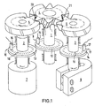
- the device for measuring the tooth flank topography of Gear teeth essentially consist of three shafts 1, 2, and 3 in one suitable for the gear type, while the measurement immutable position, the first of which Shaft 1, the toothed component to be tested, in the illustrated Case the gear 4, and the shafts 2 and 3, the measuring wheels 5 and 6 or corresponding measuring gears carry firmly on yourself.
- Fig. 1 shows a possible measuring arrangement for spur gears where these three shafts are parallel to each other are arranged.
- the shaft 2 of a measuring wheel 5 is driven by a motor 7 driven and the shaft 3 of the measuring wheel 6 via a Brake 8 braked.
- shaft 1 can also be used a brake (not shown here) a lifting of the tooth flanks lying in the power flow during exclude the measurement safely.
- All three shafts 1, 2, and 3 are with rotary encoders 9, 10 and 11, which essentially consist of a rotary encoder disk 12, 13 and 14 (e.g. radial coating disc), one suitable angle of rotation sensor 15, 16 and 17 (e.g. photocell) and the associated signal processing (not shown) consist.
- rotary encoders 9, 10 and 11 which essentially consist of a rotary encoder disk 12, 13 and 14 (e.g. radial coating disc), one suitable angle of rotation sensor 15, 16 and 17 (e.g. photocell) and the associated signal processing (not shown) consist.
- reference rotation angle indicators 18 and 19 for detecting the respective rotational position of the measuring wheels 5 and 6 with respect to fixed reference points of the device (e.g. compared to the positions of the respective rotation angle sensors 16 and 17) are provided.
- the gearing errors are recorded in the above First arrange for all right and left flanks of the gear 4 to be tested separately from each other in fixed defined by pulse steps of the rotary angle encoder 10 and 11 Steps of rotation of the measuring wheels 5 (for measuring the left flanks) and 6 (for measuring the right flanks). Via the narrow measurement tracks on the tooth flanks Measuring wheel teeth, each individually with the one to be tested Gear 4 are engaged, by rolling movable contact points with the test tooth flanks form, and about the known location of these points opposite the reference rotation angle indicators 18 and 19 are related Diameter and latitude coordinate unambiguous measuring points the specimen tooth flanks defined.
- the measurement is preferably carried out over at least one complete, depend on the number of measuring wheels and the number of test specimens Measuring cycle, i.e. over so many revolutions of the measuring wheel, as needed to all according to the chosen design possible pairings of measuring wheel and specimen teeth to go through once.
- Systematic measurement errors from the device such as. Deviations of the measurement flanks from their Sollage, in which these with imaginary ideal involutes of the Measuring wheel coincide, can be a control measurement e.g. by means of a test wheel manufactured without deviation determine and for all further measurements by arithmetic Superimposition with those measured per measuring wheel revolution Compensate for values reliably.
- Measuring points are on the gear to be tested of the considered right and left flanks each on one Measuring grid in front and can be created with the help of suitable graphic modules as deviation surfaces or so-called tooth flank topographies represent (see step 10a in Fig. 2).
- This makes possible the computational analysis of gear errors in
- the output of all Single deviations e.g. Orthodontics angular deviations, Profile angle deviations and crowning, as well the calculation and output of all other usual gear measurement values a flank direction, e.g. Single pitch error, Total division errors and single-edge gear errors.
- the tooth flanks opposite each other depend, such as local tooth thickness, spherical dimensions, radial Positional deviations of the teeth or usually only by means of a measurable double flank rolling error the rotational position of the two measuring wheels 5, 6 relative to each other with reference to the gear 4 to be tested.
- a reference angle of rotation indicators are also for this Measurement ideally the markings shown in Fig. 1 18 and 19 of the two measuring wheels 5 and 6 used, the exact position compared to a selected as the reference rotational position any measuring point of the respective flank direction of the gear to be tested for any angular position can be determined by calculation.
- the high-resolution angle signal from the angle encoder of the gear to be tested becomes the actual one Angle between the reference rotational positions of the two flank directions and thus about the deviation measurements of everyone Right and left flanks also every other angle of individual Points on opposite flanks of the gear to be tested precisely recorded.
- the one to be tested The gear and the measuring arrangement are thus the reference points the right and left flanks in relation to each other. This enables the mathematical determination of all of the above, dependent on the opposite tooth flanks Gear parameters from the topographical data of the individual tooth flanks.
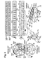
- Fig. 3 shows the principle of assigning individual rotation errors to clearly defined measuring points on the tooth flanks of the gear to be tested using the example of a helical tooth Spur gear pairing.
- the gear to be tested has here six teeth, each tooth along individual tooth direction traces measured on the head, in the middle and on the foot shall be.
- a measuring wheel with 7 teeth is used for this measuring task used to pass through a complete Measuring cycle from here a total of 6 measuring wheel revolutions all teeth of the test piece engages once with all teeth of the measuring wheel bring to.
- the teeth 1, 3 and 5 of the measuring wheel are with Measuring tracks of the known type described at the outset on the Provide tooth flanks, of which each rolling in the tooth direction at the foot of tooth 1 the track "K" the head area of everyone Test teeth, in the middle of tooth 3 the track "M” In the middle of all test teeth and on the head of tooth 5 the track “F” misses the foot area of all test teeth.
- the teeth 2, 4, 6 and 7 of the measuring wheel are as transport or support teeth executed and withdrawn on the entire flank, around a clear edge system in the area of the measuring tracks sure.
- Fig. 3 shows one possible Rotation path error of this measuring arrangement, i.e. the course of the in equidistant angle of rotation measured difference between Target rotation angles and measured angles at the individual measuring points lying one behind the other in the circumferential direction of the gear to be tested according to the evaluation described above.
- 35 + 1 36
- Equidistant measured values, i.e. 5 values per tooth mesh, recorded become.
- the two gears are used for measuring single-flanked system passed on to each other, which leads to the measuring flanks selected here aligned in the tooth direction Axial contact points on the Test tooth flanks result. These run in dependency the helix angle for the selected arrangement and direction of rotation the wheels from back to front.
- the measurement begins with the measured value No. 1 on the head from test tooth 1 measuring track "K", which here also as Reference point for the entire measurement is selected and accordingly this definition has zero deviation.
- To Measurement number 5 disengages track "K”.
- track "M” is engaged, which at the first turn of the measuring wheel is the center of test tooth 3 missing.
- Measured values No. 23 to No. 27 belong to track "F” and describe the base of the test tooth during this rotation 5. So-called are between the measuring points Transport points No. 6 to No. 11, No. 17 to No. 22 and No. 28 to No. 35, which are not in the area of a measuring track and therefore not used to measure gear errors can be.
- Fig. 4 shows a constructive embodiment of a measuring device according to the invention, in which only for understanding components of the invention required with reference numerals and the same as in Fig. 1 - are provided.
- the essence of the invention is that a complete Measuring a gear 4 to be tested can be done by it simultaneously with two measuring wheels 5 and 6 over a certain one Number of revolutions is passed on.
- the axis positions the measuring wheels are aligned with the gear to be tested according to the type of gearing to be measured.
- these are preferably parallel to Axis of the gear to be tested arranged and close in Axis direction considers a specific one with this axis Angle that is selected so that there are no overlaps can occur between the measuring wheels.
- Are in principle to measure other than parallel axis positions between the gear to be tested and the measuring wheels conceivable if the Gearing of the measuring wheel of this axis position designed accordingly becomes.
- the measuring method is based on the principle of single-flank gear testing based, is the distance between the three gears during the Measurement process fixed.
- the two measuring wheels 5 and 6 special designed for the respective measurement task, i.e. their gear data including the number of teeth will be according to suitable Design criteria set.
- the measuring wheels are provided with measuring tracks on the tooth flanks that engage get with the gear 4 to be tested to capture the to enable individual tooth flank topography of this wheel.
- the measuring wheels 5 and 6 are designed according to the State of the art DE 195 19 429 explained in more detail at the beginning C1.
- One of the measuring wheels is driven by a motor 7 which in the illustrated case via a toothed belt with the associated the measuring wheel receiving shaft 2 is coupled.
- the other measuring wheel 6 and possibly also the gear to be tested 4 are decelerated via a brake 8. This is a measurement the topographical information on both left and right flanks of the gear to be tested 4 simultaneously and in one setup. All three gears, the gear 4 to be tested and the measuring wheels 5 and 6, must be arranged on separate shafts 1, 2 and 3 and these waves 1, 2 and 3 must be corresponding Have angle encoder 9, 10 and 11.
- the analysis of local deviations and errors of individual Tooth flanks on one side in relation to each other require that Record the data in relation to a fixed position reference point 18 or 19 on the respective angle encoder 10 or 11 the measuring wheel.
- the measuring method is based on a calculation of the expected Rotational position of the gear 4 to be tested for a predetermined Rotational position of the measuring wheel of the side to be checked under the assumption faultless gearing with ideal involutes (see description of Fig. 2). The difference between the Rotation angles that are specified for ideal conditions and allowed to those recorded by the measurement the calculation of local deviations. After sorting the Measured values according to the principle described with reference to FIG.
- At least one angle encoder ideally the one with the testing gear 4 is connected to a high resolution Provide measuring device, the precise measurement of the deviations occurring in the micrometer range.
- the number of pulses per revolution can also be chosen lower, because this is only the number and location of the measuring points on the test item Gear set. But even then you have to take care that the rotational positions of these pulses are sufficient for the measuring task are exact.
- these measuring wheels are also available high-resolution rotary encoder, so the reduction the measuring points to a reasonable number e.g. also be carried out using computer technology. Then there is a Assessment of the local rotation error only after one specified number of rotary encoder pulses.
- the same reference rotation angle indicators 18 and 19 of the used two measuring wheels 5 and 6, which are also used as reference points for the right and left flanks for use come. This means that an angle of rotation can be used for each measurement Position detection of the two measuring wheels to each other. Allow for the geometry of the measurement setup the local tooth thickness of individual teeth, their radial positional deviations and others from right and left flanks jointly dependent details from the local deviations opposite tooth flanks of the test Lock gear 4.
- this measuring device which is particularly useful but not in this form for the function of the device is absolutely necessary is a corresponding loading and Clamping device for the gear wheel to be tested 4.
- the holder-clamping device for the gear 4 to be tested can based on conventional fixtures be e.g. as hydraulic or mechanical expansion mounts are trained.
- the loading and unloading process for the gear to be tested can be dependent on the respective gear type e.g. through a rectilinear or done by a helical movement. Are next to it Of course, other loading movements are also conceivable, in which the Axes of the measuring wheels and the gear to be tested from one Position in which the loading takes place in the exact measuring position moved and fixed there by a suitable device become.
- the gear 4 ' is a ring gear that with the help of the two measuring wheels 5 'and 6', in this case measuring bevel gears, is measured in one flank.
- These bevel gears too are with known measuring tracks 20 'and 21' on individual Provide tooth flanks and designed so that they a targeted measurement of the tooth flanks of individual teeth of the enable ring gears to be checked.
- the shaft 2 'of one Measuring bevel gear 5 ' is inventively driven by a motor 7' driven.
- Both other shafts that are the ring gear to be tested 4 'supporting shaft 1' and also the other measuring bevel gear 6 'supporting shaft 3' are in the case shown a brake 8'a and 8'b coupled, here as a band brake is executed and a suitable one during the measurement, approximately constant braking torque generated. This will take off of the tooth flanks, which would lead to incorrect measurements locked out.
- a corresponding design of the measuring device for bevel gears of course, a suitable loading and Include unloading options for the ring gear to be tested, around this in relation to the two measuring wheels in measuring position to bring.
- the scope for this could be e.g. by axially displacing the two measuring wheels Create waves 2 'and 3'.
- the shaft 1 'of the wheel to be tested via the two shafts Extend 2 'and 3', then the ring gear to be checked in the reverse position from above into the device and tension.
- FIG. 6 shows an example of a further embodiment the section through an inventive device for measuring of gears already mounted on a shaft or are an integral part of this wave.
- the reference numbers are analogous to those in FIG. 1 chosen and provided with a double-stroke index; you will be no longer explained here, provided that they are almost identical Describe components.
- the reference symbol 4 ′′ denotes the shaft that the gearing to be tested on wearing.
- the shaft 4 '' to be tested is between the top of the wave 1 '' which is the high resolution Angle of rotation encoder 9 '' carries, and one which forms the counter-holder 22 Tip rotatably added.
- the counter holder 22 is designed in several parts and with a corresponding Provide counter bearing.
- the via the counter holder and the shaft 4 '' to the shaft 1 '' applied, is a slip-free rotation transmission between the shaft to be tested 4 "and the rotary encoder 9 '' ensured.
- the counter holder can be used for loading and unloading 22 solved and possibly swung away.
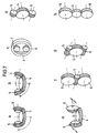
- the device according to the invention allows measurement all known types of gearing and this in almost any arrangements.
- Figures 7a-h show an overview of possible arrangements differentiated from measuring wheels according to gear types. For the sake of simplicity, these are each very schematic only the gear 4 to be tested engages with the two Measuring wheels equipped measuring wheels 5 and 6 shown.
- the 7a and 7b show possible measuring arrangements for bevel gears, 7c for measuring wheels with internal teeth, Fig. 7d for 7e for helical bevel gears (hypoid gears), 7f and 7g for worm gears and Fig. 7h for Spur gears with unequal measuring wheel diameters.
- the measuring wheels are indeed appropriate the gear data match the gear to be tested have to.
- the positions of the measuring axes in relation to the axis of the Gear to be tested can be chosen relatively freely are provided that the measuring wheels for this have it designed appropriately.
- the measuring wheels correspond to the usual engagement conditions on gear cutting machines (e.g. milling or scraping machines) pivoted relative to the toothing to be checked and how to design the corresponding tool.
- gear cutting machines e.g. milling or scraping machines
- the measuring wheels e.g. similar to Gear hobs or shaving wheels designed for a unique Assignment of the measured values to fixed points on the tooth flanks the gearing to be checked, if necessary with appropriate measuring tracks should be provided.
Abstract
Description
Die Erfindung bezieht sich auf eine Vorrichtung zum Messen
der Zahnflankentopographie von Getriebeverzahnungen der im
Oberbegriff des Patentanspruches 1 erläuterten Art.The invention relates to a device for measuring
the tooth flank topography of gear teeth in the
Preamble of
Aus der DE 195 19 429 C1 ist eine Vorrichtung zum Messen der Zahnflankentopographie von Getriebeverzahnungen bekannt, bei der nach der Einflankenwälzprüfung ein Meßrad mit einem zu prüfenden Zahnrad abwälzbar ist und wobei eine Einrichtung zur Aufzeichnung und Auswertung des dabei am zu prüfenden Zahnrad auftretenden Drehfehlerverlaufes vorgesehen ist.From DE 195 19 429 C1 is a device for measuring the tooth flank topography of gear teeth known, after the single-flank gear test a measuring wheel with a gear to be tested can be passed on and a device for recording and evaluating the thereby occurring rotation error course on the gear to be tested is provided.
Das aus dieser Schrift bekannte Meßrad weist unterschiedlich gestaltete Zähne mit jeweils besonderen Zahnflankenformen auf. Je nach Überdeckungsgrad der zu vermessenden Getriebeverzahnung sind Meßzähne und ggf. Stützzähne vorgesehen, wobei letztere soweit in ihrem verzahnungseingriff zurückgenommen sind, daß sie die entsprechende Messung an den einzelnen Meßzähnen nicht beeinträchtigen. Die Eingriffs-Zahnflanken der Meßzähne sind in bestimmten Bereichen soweit flächenmäßig abgetragen, daß erhabene radiale Meßspuren in axial versetzter Anordnung und/oder erhabene axiale Meßspuren in radial versetzter Anordnung und/oder schräg über die Zahnflanke verlaufende Meßspuren verbleiben. An aufeinanderfolgenden Meßzähnen sind radiale Meßspuren in unterschiedlichen axialen Abständen bzw. axiale Meßspuren in unterschiedlichen Höhenabständen bzw. schräg verlaufende Meßspuren unterschiedlich angeordnet. Die Zahnverhältnisse zwischen dem Meßzahnrad und dem zu prüfenden Rad sind so gewählt, daß bei mehrmaligem Umlauf bestimmte (ggf. alle) Zähne des zu prüfenden Zahnrades mit den unterschiedlichen Meßspuren in Eingriff kommen.The measuring wheel known from this document shows different designed teeth with special tooth flank shapes on. Depending on the degree of coverage of the gear teeth to be measured measuring teeth and, if necessary, supporting teeth are provided, whereby the latter so far withdrawn from their meshing are that they take the appropriate measurement on the individual Do not interfere with target teeth. The engaging tooth flanks the measuring teeth are in certain areas in terms of surface area, that raised radial measuring tracks in axially offset arrangement and / or raised axial measurement tracks in a radially offset arrangement and / or obliquely over the Traces of the tooth flank remain. On successive Measuring teeth are radial measuring tracks in different axial distances or axial measurement tracks in different Height distances or inclined measuring tracks differ arranged. The tooth relationships between the Measuring gear and the wheel to be tested are selected so that at repeated circulation of certain (possibly all) teeth of the test specimen Gear with the different measuring tracks in engagement come.
Die Aufgabe der vorliegenden Erfindung ist es, aufbauend auf der oben erwähnten Vorrichtung zum Messen der Zahnflankentopographie von Getriebeverzahnungen eine Vorrichtung zu schaffen, die in einer Aufspannung beide Flanken eines zu prüfenden Zahnrades in kurzer Zeit vermessen kann und somit beim Einsatz in der Produktion von Zahnrädern unmittelbar anwendbar ist, um bei durch das Vermessen festgestellten Abweichungen von der gewünschten Zahnflankentopographie Korrekturmaßnahmen an den Bearbeitungsmaschinen vorzunehmen.The object of the present invention is based on the above-mentioned device for measuring the tooth flank topography a device from gear teeth create the two flanks of one in one clamping testing gear can be measured in a short time and thus when used in the production of gears directly is applicable to deviations determined by the measurement corrective measures from the desired tooth flank topography on the processing machines.
Gemäß der Erfindung wird diese Aufgabe gelöst, indem an einer
Vorrichtung zum Messen der Zahnflankentopographie von
Getriebeverzahnungen der im Oberbegriff des Patentanspruches
1 erläuterten Art die im Kennzeichenteil des Patentanspruches
1 aufgezeigten Maßnahmen vorgesehen werden.According to the invention, this object is achieved by a
Device for measuring the tooth flank topography of
Gear teeth in the preamble of the
Zweckmäßige Ausgestaltungen der Erfindung ergeben sich aus den Unteransprüchen.Expedient refinements of the invention result from the subclaims.
Dadurch, daß eine vorzugsweise innen- oder außengerade-, oder schrägverzahnte, zu prüfende Verzahnung mit zwei auf der anliegenden Zahnflanke mit Meßspuren versehenen speziellen Meßverzahnungen jeweils einflankig und bei konstanter Achslage gegenüber diesen abwälzt, von denen die eine Meßverzahnung angetrieben und die andere abgebremst wird, jede der drei die Verzahnungen mit einem hochauflösenden Drehwinkelgeber gekoppelt ist und mindestens zwei der drei Drehwinkelgeber, vorzugsweise die der beiden Meßräder mit einer Drehwinkellageerkennung ausgestattet sind, können neben Teilungsfehlern und Zahnflankentopographien einzelner Rechtsund Linksflanken gleichzeitig auch die lokalen Zahndicken einzelner Zähne, ihre radialen Lageabweichungen und andere von beiden einander gegenüberliegenden Zahnflanken abhängige Verzahnungsmeßgrößen erfaßt werden.The fact that a preferably inside or outside straight, or helical gearing to be tested with two the adjacent tooth flank with special measuring tracks Measuring teeth with single flanks and constant Axial position rolls against these, one of which has a measuring toothing driven and the other braked, each the three the gears with a high-resolution rotary encoder is coupled and at least two of the three rotary angle sensors, preferably that of the two measuring wheels with one Rotation angle position detection are equipped, in addition to pitch errors and tooth flank topographies of individual legal and The local tooth thicknesses also flank to the left individual teeth, their radial positional deviations and others dependent on both opposite tooth flanks Gear measurement parameters are recorded.
Die Erfindung wird anhand der beigefügten Zeichnungen beispielhaft näher erläutert. Es zeigen:
- Fig. 1
- eine Prinzipskizze der erfindungsgemäßen Vorrichtung zur topographischen Vermessung aller Rechts- und Linksflanken von Getriebeverzahnungen am Beispiel von Stirnrädern;
- Fig. 2
- eine schematische Darstellung der Meßwerterfassung, Weiterverarbeitung und Ausgabe aller Verzahnungsmeßgrößen;
- Fig. 3
- das Prinzip der Zuordnung einzelner Drehwegfehler zu eindeutig definierten Meßpunkten auf den Zahnflanken des zu prüfenden Zahnrades;
- Fig. 4
- einen vertikalen Schnitt durch eine ausgeführte Konstruktion der erfindungsgemäßen Vorrichtung;
- Fig. 5
- eine Ausführungsform der erfindungsgemäßen Vorrichtung zum topographischen Vermessen von Kegelrädern;
- Fig. 6
- eine Ausführungsform der erfindungsgemäßen Vorrichtung zum Vermessen von Verzahnungen auf Wellen; und
- Fig. 7a-h
- eine Übersicht über einige mögliche Anordnungen der Meßräder zur Vermessung weiterer bekannter Verzahnungsarten.
- Fig. 1
- a schematic diagram of the inventive device for topographical measurement of all right and left flanks of gear teeth using the example of spur gears;
- Fig. 2
- a schematic representation of the measured value acquisition, further processing and output of all gear measurement quantities;
- Fig. 3
- the principle of assigning individual rotational path errors to clearly defined measuring points on the tooth flanks of the gear to be tested;
- Fig. 4
- a vertical section through an executed construction of the device according to the invention;
- Fig. 5
- an embodiment of the device according to the invention for topographical measurement of bevel gears;
- Fig. 6
- an embodiment of the device according to the invention for measuring toothing on shafts; and
- 7a-h
- an overview of some possible arrangements of the measuring wheels for measuring other known types of gearing.
Die Vorrichtung zum Messen der Zahnflankentopographie von
Getriebeverzahnungen besteht im wesentlichen aus drei Wellen
1, 2, und 3 in einer für den Verzahnungstyp geeigneten, während
der Messung unveränderlichen Lage, von denen die erste
Welle 1 das zu prüfende verzahnte Bauteil, im dargestellten
Fall das Zahnrad 4, aufnimmt und die Wellen 2 und 3 die Meßräder
5 und 6 aufnehmen bzw. entsprechende Meßverzahnungen
fest auf sich tragen. Fig. 1 zeigt eine mögliche Meßanordnung
für Stirnräder, bei der diese drei Wellen parallel zueinander
angeordnet sind.The device for measuring the tooth flank topography of
Gear teeth essentially consist of three
Die Welle 2 des einen Meßrades 5 wird hierbei über einen Motor
7 angetrieben und die Welle 3 des Meßrades 6 über eine
Bremse 8 abgebremst. Zusätzlich kann auch die Welle 1 mit
einer Bremse (hier nicht dargestellt) ausgestattet sein, um
ein Abheben der im Kraftfluß liegenden Zahnflanken während
der Messung sicher auszuschließen.The
Alle drei Wellen 1, 2, und 3 sind mit Drehwinkelgebern 9, 10
und 11 verbunden, die im wesentlichen aus einer Drehwinkelgeberscheibe
12, 13 und 14 (z.B. Radialstrichscheibe), einem
geeigneten Drehwinkelsensor 15, 16, und 17 (z.B. Photozelle)
und der zugehörigen Signalverarbeitung (nicht dargestellt)
bestehen.All three
An den Drehwinkelgeberscheiben 13 und 14 der beiden Meßradwellen
2 und 3 sind außerdem Referenzdrehwinkelindikatoren
18 und 19 zur Erfassung der jeweiligen Drehlage der Meßräder
5 und 6 gegenüber festen Bezugspunkten der Vorrichtung (z.B.
gegenüber den Positionen der jeweiligen Drehwinkelsensoren
16 und 17) vorgesehen.On the
An dem zu prüfenden Zahnrad 4 und den Meßrädern 5 und 6, die
sowohl gerade- als auch schrägverzahnt sein können, sind die
miteinander in Eingriff stehenden Zahnflanken bei 20 und 21
angedeutet und die entsprechenden Drehrichtungen durch Pfeile
angegeben.On the
In Fig. 2 ist die Meßwerterfassung der Vorrichtung sowie die Weiterverarbeitung der Meßwerte zur Ausgabe sämtlicher Verzahnungsmeßgrößen mit den verschiedenen Erfassungsschritten schematisch dargestellt. Die durch entsprechende Bauteile oder Software-Routinen durchzuführenden Schritte sind durch schriftliche Erläuterungen bezeichnet. Das Diagramm gibt die logische Verknüpfung dieser Schritte beim Vermessen eines zu prüfenden Zahnrades wieder:In Fig. 2, the measured value acquisition of the device and the Further processing of the measured values for the output of all gear measurement values with the different acquisition steps shown schematically. The through appropriate components or software routines to be performed written explanations. The diagram gives that logical combination of these steps when measuring a testing gear again:
Die Erfassung der Verzahnungsfehler erfolgt in der oben beschrieben
Anordnung zunächst für alle Rechts- und Linksflanken
des zu prüfenden Zahnrades 4 getrennt voneinander in festen
über Impulsschritte der Drehwinkelgeber 10 und 11 definierten
Drehwegschritten der Meßräder 5 (für die Messung der
linken Flanken) und 6 (für die Messung der rechten Flanken).
Über die mit schmalen Meßspuren auf den Zahnflanken versehenen
Meßradzähne, die jeweils einzeln mit dem zu prüfenden
Zahnrad 4 im Eingriff sind, wobei sie durch das Abwälzen
verschiebliche Berührpunkte mit den Prüflingszahnflanken
bilden, und über die bekannte Lage dieser Punkte gegenüber
den Referenzdrehwinkelindikatoren 18 und 19 sind bezüglich
Durchmesser und Breitenkoordinate eindeutige Meßstellen auf
den Prüflingszahnflanken definiert.The gearing errors are recorded in the above
First arrange for all right and left flanks
of the
Zur Erfassung einzelner Verzahnungsfehler wird ausgehend von
einem für alle drei Drehwinkelgeber gemeinsamen Startpunkt
für diese vorgegebenen Meßstellen bzw. Drehwegschritte der
zugehörige Drehweg des zu prüfenden Zahnrades ermittelt, der
sich gemäß dem Zähnezahlverhältnis zwischen den Rädern bei
abweichungsfreier Verzahnung ergeben würde. Dieser wird entsprechend
der hohen Auflösung des Drehwinkelgebers 9 des zu
prüfenden Zahnrades 4 in einen Nennwert für die Anzahl der
Drehgeberimpulse zwischen dem Startpunkt und der betrachteten
Meßstelle umgerechnet. Aus der Differenz zwischen diesem
Nennwert und dem mit Hilfe des Drehwinkelgebers 9 tatsächlich
gemessenen Istwert der Drehgeberimpulse folgt der örtliche
Drehwegfehler der zu prüfenden Verzahnung bzw. nach
Umrechnung mit Hilfe des Grundkreishalbmessers dieser Verzahnung
folgen daraus örtliche Zahnflankenformabweichungen
im Stirnschnitt.Starting with
a common starting point for all three rotary encoders
for these predetermined measuring points or steps of rotation
associated rotation of the gear to be tested, the
according to the number of teeth ratio between the wheels
deviation-free toothing would result. This will be accordingly
the high resolution of the
Die Zuordnung der bei jeder Meßradumdrehung an den einzelnen
Meßstellen des Meßrades 5 bzw. 6 ermittelten Drehwegfehler
bzw. örtlichen Zahnflankenformabweichungen zu eindeutig definierten
Punkten auf den Zahnflanken des zu prüfenden Zahnrades
4 geschieht mit Hilfe der durch den gewählten Meßaufbau
vorgegebenen Zuordnungslogik, die als Prinzip in Fig. 3
gezeigt ist und weiter unten näher erläutert wird. Hierzu
wird auf bestimmte Auslegungsinformationen des Meßrades
(z.B. Zähnezahlen und Positionen der Meßspuren auf den Meßradzahnflanken),
des zu prüfenden Zahnrades (z.B. Zähnezahl
und Geometrie) und der Meßanordnung (z.B. Meßachsabstand
zwischen Meßrad und zu prüfendem Zahnrad bei paralleler
Achslage) zurückgegriffen.The assignment of the individual with each measuring wheel revolution
Measuring points of the
Die Messung erfolgt vorzugsweise über mindestens einen kompletten, von der Meßrad- und der Prüflingszähnezahl abhängigen Meßzyklus, d.h. über so viele Umdrehungen des Meßrades, wie benötigt werden, um alle entsprechend der gewählten Auslegung möglichen Paarungen von Meßrad- und Prüflingszähnen einmal zu durchlaufen. Systematische Meßfehler aus der Vorrichtung, wie z.B. Abweichungen der Meßspurflanken von ihrer Sollage, bei der diese mit gedachten idealen Evolventen des Meßrades zusammenfallen, lassen sich über eine Kontrollmessung z.B. mittels eines abweichungsfrei gefertigten Prüfrades ermitteln und für alle weiteren Messungen durch rechnerische Überlagerung mit den pro Meßradumdrehung gemessenen Werten zuverlässig kompensieren.The measurement is preferably carried out over at least one complete, depend on the number of measuring wheels and the number of test specimens Measuring cycle, i.e. over so many revolutions of the measuring wheel, as needed to all according to the chosen design possible pairings of measuring wheel and specimen teeth to go through once. Systematic measurement errors from the device, such as. Deviations of the measurement flanks from their Sollage, in which these with imaginary ideal involutes of the Measuring wheel coincide, can be a control measurement e.g. by means of a test wheel manufactured without deviation determine and for all further measurements by arithmetic Superimposition with those measured per measuring wheel revolution Compensate for values reliably.
Nach erfolgter Zuordnung aller einzelnen Meßwerte eines Meßzyklus
zu den entsprechend der Zuordnungslogik festgelegten
Meßstellen auf dem zu prüfenden Zahnrad liegen die Meßwerte
der betrachteten Rechts- und Linksflanken jeweils auf einem
Meßgitter vor und lassen sich mit Hilfe geeigneter Grafikmodule
als Abweichungsflächen oder sogenannte Zahnflankentopographien
darstellen (siehe Schritt 10a in Fig. 2). Dies ermöglicht
die rechnerische Analyse der Verzahnungsfehler im
Hinblick auf den vorgesehenen Einsatzfall, die Ausgabe sämtlicher
Einzelabweichungen, wie z.B. Zahnrichtungswinkelabweichungen,
Profilwinkelabweichungen und Balligkeiten, sowie
die Berechnung und Ausgabe aller weiteren üblichen Verzahnungsmeßgrößen
einer Flankenrichtung, wie z.B. Einzelteilungsfehler,
Summenteilungsfehler und Einflankenwälzfehler.After assignment of all individual measurement values of a measurement cycle
to those determined according to the assignment logic
Measuring points are on the gear to be tested
of the considered right and left flanks each on one
Measuring grid in front and can be created with the help of suitable graphic modules
as deviation surfaces or so-called tooth flank topographies
represent (see
Durch Verwendung eines gemeinsamen Zählerstartpunktes für alle drei Drehgeber beschreiben alle einzelnen Meßergebnisse die Abweichungen des zu prüfenden Zahnrades jeweils in Relation zu einem für die betrachtete Flankenrichtung einheitlichen Bezugspunkt, an dem die Abweichungen per Definition gleich Null gesetzt sind. Sie lassen sich durch Addition oder Subtraktion eines für alle Meßpunkte dieser Flankenrichtung konstanten Überlagerungswertes rein rechnerisch auf jeden anderen Bezugspunkt einer beliebigen Zahnflanke des zu prüfenden Zahnrades umrechnen.By using a common counter start point for all three encoders describe all individual measurement results the deviations of the gear to be tested in relation to a uniform one for the considered flank direction Reference point at which the deviations by definition are set to zero. They can be added or subtract one for all measuring points of this flank direction constant superimposition value purely arithmetically any other reference point of any tooth flank of the Convert the checking gear.
Zur Erfassung bzw. Berechnung derjenigen Verzahnungsmeßgrößen,
die von beiden einander gegenüberliegenden Zahnflanken
abhängen, wie z.B. örtliche Zahndicken, Kugelmaße, radiale
Lageabweichungen der Zähne oder der üblicherweise nur mittels
einer Zweiflankenwälzprüfung meßbaren Zweiflankenwälzfehler
wird zusätzlich die Drehlage der beiden Meßräder 5, 6
zueinander bezogen auf das zu prüfende Zahnrad 4 genau erfaßt.
Als Referenzdrehwinkelindikatoren werden auch für diese
Messung idealerweise die in Fig. 1 dargestellten Markierungen
18 und 19 der beiden Meßräder 5 und 6 verwendet, deren
genaue Lage gegenüber einer als Referenzdrehlage ausgewählten
beliebigen Meßstelle der jeweiligen Flankenrichtung
des zu prüfenden Zahnrades für beliebige Winkelstellungen
rechnerisch bestimmt werden kann.To record or calculate those gear measurement parameters,
the tooth flanks opposite each other
depend, such as local tooth thickness, spherical dimensions, radial
Positional deviations of the teeth or usually only by means of
a measurable double flank rolling error
the rotational position of the two measuring
Mit Hilfe des hochauflösenden Drehwinkelsignals vom Drehwinkelgeber des zu prüfenden Zahnrades wird so der tatsächliche Winkel zwischen den Referenzdrehlagen der beiden Flankenrichtungen und damit über die Abweichungsmessungen aller Rechts- und Linksflanken auch jeder andere Winkel einzelner Punkte an gegenüberliegenden Flanken des zu prüfenden Zahnrades genau erfaßt. Unter Berücksichtigung der notwendigen Auslegungsinformationen über die Meßräder, das zu prüfende Zahnrad sowie die Meßanordnung stehen so also die Bezugspunkte der Rechts- und Linksflanken in Beziehung zueinander. Dies ermöglicht die rechnerische Ermittlung aller oben genannten, von den sich gegenüberliegenden Zahnflanken abhängigen Verzahnungsmeßgrößen aus den topographischen Daten der einzelnen Zahnflanken.With the help of the high-resolution angle signal from the angle encoder of the gear to be tested becomes the actual one Angle between the reference rotational positions of the two flank directions and thus about the deviation measurements of everyone Right and left flanks also every other angle of individual Points on opposite flanks of the gear to be tested precisely recorded. Taking into account the necessary Design information about the measuring wheels, the one to be tested The gear and the measuring arrangement are thus the reference points the right and left flanks in relation to each other. This enables the mathematical determination of all of the above, dependent on the opposite tooth flanks Gear parameters from the topographical data of the individual tooth flanks.
Fig. 3 zeigt das Prinzip der Zuordnung einzelner Drehwegfehler
zu eindeutig definierten Meßpunkten auf den Zahnflanken
des zu prüfenden Zahnrades am Beispiel einer schrägverzahnten
Stirnradpaarung. Das zu prüfende Zahnrad hat hierbei
sechs Zähne, von denen jeder Zahn entlang einzelner Zahnrichtungsspuren
am Kopf, in der Mitte und am Fuß vermessen
werden soll. Für diese Meßaufgabe wird ein Meßrad mit 7 Zähnen
verwendet, um beim Abwälzen über einen vollständigen
Meßzyklus von hier insgesamt 6 Meßradumdrehungen alle Zähne
des Prüflings einmal mit allen Zähnen des Meßrades in Eingriff
zu bringen. Die Zähne 1, 3 und 5 des Meßrades sind mit
Meßspuren der eingangs beschriebenen, bekannten Art auf den
Zahnflanken versehen, von denen jeweils in Zahnrichtung abwälzend
am Fuß von Zahn 1 die Spur "K" den Kopfbereich aller
Prüflingszähne, in der Mitte von Zahn 3 die Spur "M" die
Mitte aller Prüflingszähne und am Kopf von Zahn 5 die Spur
"F" den Fußbereich aller Prüflingszähne vermißt. Die Zähne
2, 4, 6 und 7 des Meßrades sind als Transport- oder Stützzähne
ausgeführt und auf der gesamten Flanke zurückgenommen,
um im Bereich der Meßspuren eine eindeutige Flankenanlage
sicherzustellen.Fig. 3 shows the principle of assigning individual rotation errors
to clearly defined measuring points on the tooth flanks
of the gear to be tested using the example of a helical tooth
Spur gear pairing. The gear to be tested has here
six teeth, each tooth along individual tooth direction traces
measured on the head, in the middle and on the foot
shall be. A measuring wheel with 7 teeth is used for this measuring task
used to pass through a complete
Measuring cycle from here a total of 6 measuring wheel revolutions all teeth
of the test piece engages once with all teeth of the measuring wheel
bring to. The
Der rechte mittlere Teil von Fig. 3 zeigt einen möglichen Drehwegfehler dieser Meßanordnung, also den Verlauf der in äquidistanten Drehwinkelschritten gemessenen Differenz zwischen Solldrehwinkeln und gemessenen Winkeln an den einzelnen in Umfangsrichtung hintereinanderliegenden Meßstellen des zu prüfenden Zahnrades gemäß der oben beschriebenen Auswertung. Zur anschaulichen Beschreibung der Zuordnungslogik ist hierbei vorausgesetzt, daß pro Meßradumdrehung 35+1=36 äquidistante Meßwerte, also 5 Werte pro Zahneingriff, aufgezeichnet werden. Zum Messen werden die beiden Zahnräder bei einflankiger Anlage zueinander abgewälzt, wodurch sich an den hier gewählten, in Zahnrichtung ausgerichteten Meßspurflanken in axialer Richtung wandernde Berührpunkte auf den Prüflingszahnflanken ergeben. Diese laufen in Abhängigkeit vom Schrägungswinkel bei der gewählten Anordnung und Drehrichtung der Räder von hinten nach vorne.The right middle part of Fig. 3 shows one possible Rotation path error of this measuring arrangement, i.e. the course of the in equidistant angle of rotation measured difference between Target rotation angles and measured angles at the individual measuring points lying one behind the other in the circumferential direction of the gear to be tested according to the evaluation described above. For a clear description of the assignment logic it is assumed that 35 + 1 = 36 Equidistant measured values, i.e. 5 values per tooth mesh, recorded become. The two gears are used for measuring single-flanked system passed on to each other, which leads to the measuring flanks selected here aligned in the tooth direction Axial contact points on the Test tooth flanks result. These run in dependency the helix angle for the selected arrangement and direction of rotation the wheels from back to front.
Die Messung beginnt mit dem Meßwert Nr. 1 auf der den Kopf
von Prüflingszahn 1 vermessenden Spur "K", der hier auch als
Bezugspunkt für die gesamte Messung gewählt ist und entsprechend
dieser Definition die Abweichung Null aufweist. Nach
Meßwert Nr. 5 kommt Spur "K" außer Eingriff. Von Meßwert Nr.
12 bis Nr. 16 befindet sich Spur "M" in Eingriff, welche bei
der ersten Meßradumdrehung die Mitte von Prüflingszahn 3
vermißt. Die Meßwerte Nr. 23 bis Nr. 27 gehören zu Spur "F"
und beschreiben bei dieser Umdrehung den Fuß von Prüflingszahn
5. Zwischen den Meßpunkten liegen jeweils sogenannte
Transportpunkte Nr. 6 bis Nr. 11, Nr. 17 bis Nr. 22 und Nr.
28 bis Nr. 35, die nicht im Bereich einer Meßspur liegen und
daher nicht zur Messung von Verzahnungsfehlern herangezogen
werden können.The measurement begins with the measured value No. 1 on the head
from
Nach einer Meßradumdrehung wiederholt sich dieser Zyklus mit
neuen Zahnkombinationen entsprechend der Zuordnungslogik im
Bild oben rechts. Dementsprechend ergeben sich die vollständigen
Informationen der Zahnflankenformen beispielsweise für
Prüflingszahn 1 für die Kopfspur "K" aus Meßradumdrehung 1,
die Spur "M" in Zahnmitte aus Umdrehung 5 und die Fußspur
"F" aus Umdrehung 3. Mit den zugehörigen Breiten- und Durchmesserkoordinaten
der einzelnen Meßwerte liegt damit die Zuordnung
einzelner Meßwerte zu festen Punkten auf den Zahnflanken
der Prüflingszähne fest.After one revolution of the measuring wheel, this cycle is repeated
new tooth combinations according to the assignment logic in
Top right picture. Accordingly, the complete result
Information of the tooth flank shapes for example for
Nach einem vollständigen Meßzyklus von insgesamt 6 Meßradumdrehungen liegen alle Informationen der hier vermessenen Rechtsflanken einmal vor. Bei korrekter Aufzeichnung würde sich daher beim Weiterdrehen für die siebte Meßradumdrehung wieder derselbe Drehwegfehlerverlauf wie bei der ersten Meßradumdrehung ergeben. Natürlich gilt für andere Auslegungen und Meßspuranordnungen eine u.U. ganz andere Zuordnungslogik; diese ist aber aus der Auslegungsinformation der Meßräder und der Festlegung der Meßwinkelschritte immer eindeutig bestimmbar. After a complete measuring cycle of a total of 6 measuring wheel revolutions all information of the measured here Right flanks once. If recorded correctly, would therefore, when turning further for the seventh revolution of the measuring wheel again the same rotation path error curve as for the first measuring wheel revolution result. Of course, this applies to other interpretations and measuring track arrangements may be completely different allocation logic; but this is from the design information of the measuring wheels and the determination of the measuring angle steps always clearly determinable.
Fig. 4 zeigt eine konstruktive Ausführung einer Meßvorrichtung gemäß der Erfindung, bei der nur die zum Verständnis der Erfindung erforderlichen Bauteile mit Bezugszeichen-und zwar den gleichen wie in Fig. 1 - versehen sind.Fig. 4 shows a constructive embodiment of a measuring device according to the invention, in which only for understanding components of the invention required with reference numerals and the same as in Fig. 1 - are provided.
Die Verwendung der erfindungsgemäßen Vorrichtung wird im nachfolgenden mit Hilfe der Figuren 1 und 4 erläutert:The use of the device according to the invention is in explained below with the aid of FIGS. 1 and 4:
Das Wesentliche der Erfindung ist, daß ein vollständiges
Vermessen eines zu prüfenden Zahnrades 4 erfolgen kann, indem
es gleichzeitig mit zwei Meßrädern 5 und 6 über eine bestimmte
Anzahl von Umdrehungen abgewälzt wird. Die Achslagen
der Meßräder gegenüber dem zu prüfenden Zahnrad richten sich
nach der Art der zu vermessenden Verzahnung. Bei der Vermessung
von Stirnrädern sind diese vorzugsweise parallel zur
Achse des zu prüfenden Zahnrades angeordnet und schließen in
Achsrichtung betrachtet mit dieser Achse einen bestimmten
Winkel ein, der so gewählt ist, daß keine Überschneidungen
zwischen den Meßrädern auftreten können. Prinzipiell sind
zur Vermessung auch andere als parallele Achslagen zwischen
dem zu prüfenden Zahnrad und den Meßrädern denkbar, wenn die
Verzahnung des Meßrades dieser Achslage entsprechend gestaltet
wird.The essence of the invention is that a complete
Measuring a
Da das Meßverfahren auf dem Prinzip der Einflankenwälzprüfung
basiert, ist der Abstand der drei Zahnräder während des
Meßvorgangs fixiert. Im Gegensatz zu den bekannten Einflankenmeßvorrichtungen
sind die beiden Meßräder 5 und 6 speziell
für die jeweilige Meßaufgabe ausgelegt, d.h. ihre Verzahnungsdaten
einschließlich der Zähnezahl werden nach geeigneten
Auslegungskriterien festgelegt. Die Meßräder sind
mit Meßspuren auf den Zahnflanken versehen, die in Eingriff
mit dem zu prüfenden Zahnrad 4 gelangen, um ein Erfassen der
individuellen Zahnflankentopographie dieses Rades zu ermöglichen.
Die Auslegung der Meßräder 5 und 6 erfolgt gemäß dem
eingangs näher erläuterten Stand der Technik DE 195 19 429
C1.Since the measuring method is based on the principle of single-flank gear testing
based, is the distance between the three gears during the
Measurement process fixed. In contrast to the known single-flank measuring devices
are the two measuring
Eines der Meßräder ist über einen Motor 7 angetrieben, der
im dargestellten Fall über einen Zahnriemen mit der zugehörigen,
das Meßrad aufnehmenden Welle 2 gekoppelt ist. Das
andere Meßrad 6 sowie eventuell auch das zu prüfende Zahnrad
4 werden über eine Bremse 8 verzögert. Dadurch wird ein Vermessen
der topographischen Informationen an beiden - den
linken und den rechten - Flanken des zu prüfenden Zahnrades
4 gleichzeitig und in einer Aufspannung ermöglicht. Alle
drei Zahnräder, das zu prüfende Zahnrad 4 und die Meßräder 5
und 6, müssen dazu auf getrennten Wellen 1, 2 und 3 angeordnet
sein und diese Wellen 1, 2 und 3 müssen entsprechende
Drehwinkelgeber 9, 10 und 11 aufweisen.One of the measuring wheels is driven by a
Die Analyse der lokalen Abweichungen und Fehler einzelner
Zahnflanken einer Seite in Relation zueinander erfordert die
Aufzeichnung der Daten in Bezug auf einen festen Lagebezugspunkt
18 bzw. 19 am jeweiligen Drehwinkelgeber 10 bzw. 11
des Meßrades. Wie bereits oben beschrieben, basiert das Meßverfahren
auf einer Berechnung der jeweils zu erwartenden
Drehlage des zu prüfenden Zahnrades 4 für eine vorgegebene
Drehlage des Meßrades der zu prüfenden Seite unter der Annahme
einer fehlerfreien Verzahnung mit idealen Evolventen
(siehe Beschreibung zu Fig. 2). Die Differenz zwischen den
Drehwinkeln, die für ideale Verhältnisse vorgegeben sind und
denen, die durch die Messung aufgezeichnet werden, erlaubt
die Berechnung örtlicher Abweichungen. Nach Sortierung der
Meßwerte gemäß dem anhand von Fig. 3 beschriebenen Prinzip
lassen sich diese als örtliche Abweichungen auf einzelnen
Zahnflanken des zu prüfenden Zahnrades 4 in Relation zu dem
gewählten Lagebezugspunkt und damit auch zu beliebigen anderen
Punkten auf den Zahnflanken darstellen, wodurch Rückschlüsse
auf sämtliche Verzahnungsfehler aller Rechts- und
aller Linksflanken einschließlich der einzelnen Zahnflankentopographien
möglich sind.The analysis of local deviations and errors of individual
Tooth flanks on one side in relation to each other require that
Record the data in relation to a fixed
Zumindest ein Drehwinkelgeber, idealerweise der mit dem zu
prüfenden Zahnrad 4 verbundene, ist mit einer hochauflösenden
Meßvorrichtung versehen, die ein präzises Vermessen der
auftretenden Abweichungen im Mikrometerbereich ermöglicht.
Für die zwei anderen Drehwinkelgeber, idealerweise die der
beiden Meßräder 5 und 6, kann die Anzahl der Impulse pro Umdrehung
auch geringer gewählt werden, denn hiermit wird lediglich
die Anzahl und die Lage der Meßpunkte am zu prüfenden
Zahnrad festgelegt. Auch dann ist aber darauf zu achten,
daß die Drehlagen dieser Impulse für die Meßaufgabe ausreichend
genau sind. Werden diese Meßräder dagegen auch mit
hochauflösenden Drehwinkelgebern bestückt, so kann die Reduzierung
der Meßpunkte auf eine sinnvolle Anzahl z.B. auch
computertechnisch durchgeführt werden. Es erfolgt dann eine
Beurteilung der lokalen Drehwegfehler nur jeweils nach einer
festgelegten Anzahl von Drehwinkelgeberimpulsen.At least one angle encoder, ideally the one with the
Zur Erfassung der von beiden einander gegenüberliegenden
Zahnflanken abhängigen Verzahnungsmeßgrößen werden vorzugsweise
dieselben Referenzdrehwinkelindikatoren 18 und 19 der
beiden Meßräder 5 und 6 verwendet, die ja auch als Lagebezugspunkte
für die Rechts- und Linksflanken zur Anwendung
kommen. Damit kann bei jeder Messung auch eine drehwinkelmäßige
Lageerfassung der beiden Meßräder zueinander erfolgen.
Unter Berücksichtigung der Geometrie der Meßanordnung lassen
sich hierüber die lokalen Zahndicken einzelner Zähne, ihre
radialen Lageabweichungen und andere von Rechts- und Linksflanken
gemeinsam abhängigen Details aus den lokalen Abweichungen
einander gegenüberliegender Zahnflanken des zu prüfenden
Zahnrades 4 feststellen.To detect the opposing of both
Tooth flank-dependent gear measurement values are preferred
the same reference
Ein weiteres Merkmal der in Fig. 4 dargestellten Ausführungsform
dieser Meßvorrichtung, das besonders zweckmäßig,
aber in dieser Form für die Funktion der Vorrichtung nicht
zwingend notwendig ist, ist eine entsprechende Lade- und
Spannvorrichtung für das zu prüfende Zahnrad 4. Die Aufnahme-Klemmvorrichtung
für das zu prüfende Zahnrad 4 kann auf
der Basis von herkömmlichen Spannvorrichtungen aufgebaut
sein, die z.B. als hydraulische oder mechanische Spreizaufnahmen
ausgebildet sind. Der Belade- und Entladevorgang für
das zu prüfende Zahnrad kann hierbei in Abhängigkeit von der
jeweiligen Verzahnungsart z.B. durch eine geradlinige oder
durch eine schraubenförmige Bewegung erfolgen. Daneben sind
natürlich auch andere Ladebewegungen denkbar, bei denen die
Achsen der Meßräder und des zu prüfenden Zahnrades aus einer
Position, in der das Laden erfolgt, in die genaue Meßposition
verschoben und dort durch eine geeignete Vorrichtung fixiert
werden.Another feature of the embodiment shown in FIG. 4
this measuring device, which is particularly useful
but not in this form for the function of the device
is absolutely necessary is a corresponding loading and
Clamping device for the gear wheel to be tested 4. The holder-clamping device
for the
Fig. 5 zeigt eine Ausführungsform der erfindungsgemäßen Vorrichtung zum Vermessen von Kegelrädern, bei der die Bauteile mit den gleichen, nur mit einem Strich-Index versehenen Bezugszeichen entsprechend der Beschreibung zu Fig. 1 versehen sind. Hierbei ist das Zahnrad 4' ein Tellerrad, das mit Hilfe der beiden Meßräder 5' und 6', in diesem Fall Meßkegelräder, jeweils einflankig vermessen wird. Auch diese Kegelräder sind mit bekannten Meßspuren 20' und 21' auf einzelnen Zahnflanken versehen und sinngemäß so ausgelegt, daß diese eine gezielte Vermessung der Zahnflanken einzelner Zähne des zu prüfenden Tellerrades ermöglichen. Die Welle 2' des einen Meßkegelrades 5' wird erfindungsgemäß durch einen Motor 7' angetrieben. Beide anderen Wellen, die das zu prüfende Tellerrad 4' tragende Welle 1' und auch die das andere Meßkegelrad 6' tragende Welle 3' sind im dargestellten Fall mit einer Bremse 8'a und 8'b gekoppelt, die hier als Bandbremse ausgeführt ist und während der Messung ein geeignetes, etwa konstantes Bremsmoment erzeugt. Hierdurch wird ein Abheben der Zahnflanken, das zu Fehlmessungen führen würde, sicher ausgeschlossen.5 shows an embodiment of the device according to the invention for measuring bevel gears in which the components with the same reference numerals, but with a prime index provided according to the description of FIG. 1 are. Here, the gear 4 'is a ring gear that with the help of the two measuring wheels 5 'and 6', in this case measuring bevel gears, is measured in one flank. These bevel gears too are with known measuring tracks 20 'and 21' on individual Provide tooth flanks and designed so that they a targeted measurement of the tooth flanks of individual teeth of the enable ring gears to be checked. The shaft 2 'of one Measuring bevel gear 5 'is inventively driven by a motor 7' driven. Both other shafts that are the ring gear to be tested 4 'supporting shaft 1' and also the other measuring bevel gear 6 'supporting shaft 3' are in the case shown a brake 8'a and 8'b coupled, here as a band brake is executed and a suitable one during the measurement, approximately constant braking torque generated. This will take off of the tooth flanks, which would lead to incorrect measurements locked out.
Eine entsprechende konstruktive Ausführung der Meßvorrichtung für Kegelräder müßte natürlich eine geeignete Lade- und Entlademöglichkeit für das zu prüfende Tellerrad beinhalten, um dieses gegenüber den beiden Meßrädern in Meßposition bringen zu können. Der Freiraum hierfür ließe sich z.B. durch axiales Verschieben der beiden die Meßräder aufnehmenden Wellen 2' und 3' schaffen. Vorstellbar ist aber auch, die Welle 1' des zu prüfenden Rades über die beiden Wellen 2' und 3' hinaus zu verlängern, um dann das zu prüfende Tellerrad in umgekehrter Lage von oben in die Vorrichtung einzulegen und zu spannen.A corresponding design of the measuring device for bevel gears, of course, a suitable loading and Include unloading options for the ring gear to be tested, around this in relation to the two measuring wheels in measuring position to bring. The scope for this could be e.g. by axially displacing the two measuring wheels Create waves 2 'and 3'. But it is also conceivable the shaft 1 'of the wheel to be tested via the two shafts Extend 2 'and 3', then the ring gear to be checked in the reverse position from above into the device and tension.
Fig. 6 zeigt als Beispiel für eine weitere Ausführungsform
den Schnitt durch eine erfindungsgemäße Vorrichtung zum Vermessen
von Verzahnungen, die bereits auf einer welle montiert
oder fester Bestandteil dieser Welle sind. Die Bezugszeichen
sind hierbei sinngemäß entsprechend denen in Fig. 1
gewählt und mit einem Doppel-Strich-Index versehen; sie werden
hier nicht mehr erläutert, sofern diese nahezu identische
Bauteile beschreiben. Das Bezugszeichen 4'' kennzeichnet
die Welle, die die zu prüfende Verzahnung auf sich
trägt. Die zu prüfende Welle 4'' wird bei der Messung zwischen
der Spitze der Welle 1'', die den hochauflösenden
Drehwinkelgeber 9'' trägt, und einer den Gegenhalter 22 bildenden
Spitze drehbar aufgenommen. Der Gegenhalter 22 ist
hierfür mehrteilig ausgeführt und mit einem entsprechenden
Gegenlager versehen. Durch entsprechende Spannkräfte, die
über den Gegenhalter und die Welle 4'' auf die Welle 1''
aufgebracht werden, ist eine schlupffreie Drehübertragung
zwischen der zu prüfenden Welle 4 " und dem Drehwinkelgeber
9'' sichergestellt. Zum Be- und Entladen kann der Gegenhalter
22 gelöst und ggf. weggeschwenkt werden.6 shows an example of a further embodiment
the section through an inventive device for measuring
of gears already mounted on a shaft
or are an integral part of this wave. The reference numbers
are analogous to those in FIG. 1
chosen and provided with a double-stroke index; you will be
no longer explained here, provided that they are almost identical
Describe components. The
Die erfindungsgemäße Vorrichtung erlaubt im Prinzip die Vermessung aller bekannten Verzahnungsarten und dies in nahezu beliebigen Anordnungen.In principle, the device according to the invention allows measurement all known types of gearing and this in almost any arrangements.
Die Figuren 7a-h zeigen eine Übersicht über mögliche Anordnungen
von Meßrädern unterschieden nach Verzahnungsarten.
Hierbei sind der Einfachheit halber sehr schematisch jeweils
nur das zu prüfende Zahnrad 4 im Eingriff mit den beiden mit
Meßspuren ausgestatteten Meßrädern 5 und 6 dargestellt. Die
Fig. 7a und 7b zeigen mögliche Meßanordnungen für Kegelräder,
7c für Meßräder mit Innenverzahnung, Fig. 7d für
Schraubräder, Fig. 7e für Kegelschraubräder (Hypoidräder),
die Fig. 7f und 7g für Schneckenräder sowie Fig. 7h für
Stirnräder mit ungleichen Meßraddurchmessern.Figures 7a-h show an overview of possible arrangements
differentiated from measuring wheels according to gear types.
For the sake of simplicity, these are each very schematic
only the
Es ist zu berücksichtigen, daß die Meßräder zwar entsprechend den Verzahnungsdaten zu dem zu prüfenden Zahnrad passen müssen. Die Lagen der Meßachsen gegenüber der Achse des zu prüfenden Zahnrades können hierbei aber relativ frei gewählt werden, vorausgesetzt, daß sich die Meßräder hierfür passend auslegen lassen.It should be borne in mind that the measuring wheels are indeed appropriate the gear data match the gear to be tested have to. The positions of the measuring axes in relation to the axis of the Gear to be tested can be chosen relatively freely are provided that the measuring wheels for this have it designed appropriately.
Voraussetzung ist immer, daß die Achslagen der Zahnräder zueinander während der Messung fest positioniert sind, und dabei eine einflankige Anlage zwischen den Zahnrädern sichergestellt ist. Für jede dieser Anordnungen muß natürlich auch hier eine geeignete konstruktive Ausführungsform der Meßvorrichtung festgelegt werden, die eine einfache Be- und Entladung der zu prüfenden Verzahnung ermöglicht. Darüber hinaus ist für die Vermessung von Schnecken- und Schraubrädern darauf zu achten, daß keine Selbsthemmung bei der Übertragung des Drehmomentes vom großen auf das kleine Rad auftritt. Diese kann in gewissen Grenzen z.B. durch geeignete Festlegung der Zähnezahlen der Meßräder vermieden werden. Da die Auslegung der Meßräder individuell für die jeweilige Meßaufgabe erfolgt und diese unabhängig von der späteren Anordnung des zu prüfenden Zahnrades im Getriebe ist, bestehen daneben u.U. auch andere konstruktive Möglichkeiten zur Vermeidung von Selbsthemmung, wie z.B. die Wahl eines geeigneten Kreuzungswinkels zwischen den Meßrädern und dem zu prüfenden Zahnrad.The prerequisite is always that the axis positions of the gears to each other are firmly positioned during the measurement, while doing so ensures a single-flank system between the gears is. For each of these arrangements, of course, too here a suitable constructive embodiment of the measuring device be established, the simple loading and unloading the gearing to be checked. Furthermore is for measuring worm and screw gears on it to ensure that no self-locking during transmission of the torque from the big to the small wheel occurs. Within certain limits, this can e.g. by appropriate determination the number of teeth of the measuring wheels can be avoided. Since the Design of the measuring wheels individually for the respective measuring task takes place and this regardless of the later arrangement of the gear to be checked is in the gearbox u.U. other constructive ways to avoid self-locking, e.g. the choice of a suitable crossing angle between the measuring wheels and the one to be tested Gear.
Weitere grundlegende Anordnungsmöglichkeiten ergeben sich, wenn die Meßräder entsprechend den üblichen Eingriffsverhältnissen an Verzahnungsmaschinen (z.B. Fräs- oder Schabmaschinen) gegenüber der zu prüfenden Verzahnung geschwenkt und dabei wie das entsprechende Werkzeug gestaltet werden. Zur Vermessung von Stirnradverzahnungen würde dies als Meßanordnung beispielsweise das Abwälzen zwischen den Meßrädern und dem zu prüfenden Zahnrad unter einem bestimmten Achskreuzwinkel bedeuten, wobei die Meßräder z.B. ähnlich wie Wälzfräser oder Schabräder gestaltet und für eine eindeutige Zuordnung der Meßwerte zu festen Punkten auf den Zahnflanken der zu prüfenden Verzahnung ggf. mit entsprechenden Meßspuren versehen werden müßten.There are further basic arrangement options, if the measuring wheels correspond to the usual engagement conditions on gear cutting machines (e.g. milling or scraping machines) pivoted relative to the toothing to be checked and how to design the corresponding tool. To measure spur gear teeth, this would be used as a measuring arrangement for example rolling between the measuring wheels and the gear to be tested at a certain axis cross angle mean, the measuring wheels e.g. similar to Gear hobs or shaving wheels designed for a unique Assignment of the measured values to fixed points on the tooth flanks the gearing to be checked, if necessary with appropriate measuring tracks should be provided.
Claims (5)
- Device for measuring the tooth flank topography of gear toothing according to the single flank rolling test with a measuring wheel which can be rolled with a gear wheel to be tested in such a way that only one toothed flank of the gear wheel engages with a measuring wheel and wherein the engagement toothed flanks have measuring tracks and a device for recording and evaluating the progression of rotation defects (.....) of the gear wheel (4) that is to be tested
characterised in thatthe gear wheel (4) to be tested engages with measuring tracks (20, 21) of two measuring wheels (5, 6) arranged at any given angle, of which one measuring wheel (5) is driven by a drive (7) and the other measuring wheel (6) is braked,a rotation angle indicator (9, 10, 11) is assigned to each of the three wheels (4, 5, 6), andat least two of the three rotation angle indicators (9, 10, 11) are formed in a manner facilitating a rotation angle position recognition, anda recording device is provided, by means of which in consideration of the two rotation path error progressions measured between the gear wheel (4) to be tested and the respective measuring wheel (5 or 6) a recording of the tooth flank topography of the respectively measured right and left flanks in relation to any given common reference point is effected. - Device according to claim 1
characterised in thatthe recording device is formed for the purpose of determining toothing errors which depend in common upon the respective tooth flanks lying opposite each other. - Device according to claim 1 or 2
characterised in thatthe gear wheel (4) to be tested is braked by means of an additional braking device (8'a). - Device according to one of the claims 1 to 3
characterised in thatone of the three rotation angle indicators (9, 10, 11), preferably the indicator (9) of the gear wheel (4) to be tested, is formed in a high resolution way and the other two indicators (10, 11) indicate a lower impulse number suited to the respective measurement, but sufficiently highly accurate in relation to the rotation angle position of the impulses. - Device according to one of the claims 1 to 4
characterised in thatthe measuring tracks (20, 21) are arranged in such a way that with the aid of the measured rotation angle positions localisable contact regions of the measuring tracks are formed with the tooth flanks of the gear wheel (4) to be tested and the individual measuring tracks of each measurement wheel (5, 6) are displaced against each other in such a way that contact regions of the tooth flanks of the gear wheel to be tested displaced in a different way against each other are recorded.
Applications Claiming Priority (3)
| Application Number | Priority Date | Filing Date | Title |
|---|---|---|---|
| DE19719249 | 1997-05-07 | ||
| DE19719249A DE19719249C1 (en) | 1997-05-07 | 1997-05-07 | Apparatus for measuring tooth edge topography of gear teeth |
| PCT/EP1998/002555 WO1998050772A1 (en) | 1997-05-07 | 1998-04-30 | Device for complete measuring of gear toothing, including tooth flank topography |
Publications (2)
| Publication Number | Publication Date |
|---|---|
| EP0980514A1 EP0980514A1 (en) | 2000-02-23 |
| EP0980514B1 true EP0980514B1 (en) | 2004-01-07 |
Family
ID=7828858
Family Applications (1)
| Application Number | Title | Priority Date | Filing Date |
|---|---|---|---|
| EP98924251A Expired - Lifetime EP0980514B1 (en) | 1997-05-07 | 1998-04-30 | Device for complete measuring of gear toothing, including tooth flank topography |
Country Status (4)
| Country | Link |
|---|---|
| EP (1) | EP0980514B1 (en) |
| AT (1) | ATE257591T1 (en) |
| DE (2) | DE19719249C1 (en) |
| WO (1) | WO1998050772A1 (en) |
Cited By (1)
| Publication number | Priority date | Publication date | Assignee | Title |
|---|---|---|---|---|
| WO2019170403A1 (en) * | 2018-03-07 | 2019-09-12 | Gleason-Pfauter Maschinenfabrik Gmbh | Contact rolling tester, machining system and method for the dual-flank roll testing of a toothing |
Families Citing this family (9)
| Publication number | Priority date | Publication date | Assignee | Title |
|---|---|---|---|---|
| AT502910B1 (en) * | 2002-10-10 | 2009-07-15 | M & R Automation Gmbh | METHOD AND ARRANGEMENT FOR RECORDING AND EVALUATING MEASUREMENT DATA OF A TRANSMISSION DEVICE |
| AT502909B1 (en) * | 2002-10-10 | 2009-07-15 | M & R Automation Gmbh | ASSEMBLY DEVICE FOR TRANSMISSION AND METHOD FOR ADJUSTING THE TOOTHPLAIN GAME OF A TRANSMISSION GEARBAR |
| FR2974901A1 (en) * | 2011-05-05 | 2012-11-09 | Peugeot Citroen Automobiles Sa | Method for dynamically measuring twist defect of gear wheel tooth, involves determining twist defect from angular difference between directions of actual profiles of tooth, viewed in measuring planes |
| DE102011079384B4 (en) * | 2011-07-19 | 2013-09-26 | Trimble Jena Gmbh | Method and apparatus for determining a quality of a transmission assembly from at least two gears |
| DE102013003795A1 (en) * | 2013-03-05 | 2014-09-11 | Liebherr-Verzahntechnik Gmbh | Machining process for hard finishing of noise optimized gears on a gear cutting machine |
| DE102014007646A1 (en) | 2014-05-23 | 2015-11-26 | Liebherr-Verzahntechnik Gmbh | Method for determining the position of the involute in gears |
| DE102015100949A1 (en) * | 2015-01-22 | 2016-07-28 | Wittenstein Ag | angle gear |
| CN106813561B (en) * | 2017-03-31 | 2023-04-18 | 慈溪市三佩机械有限公司 | Internal tooth common normal line measuring device of automobile electronic brake assisting system |
| WO2022242906A1 (en) | 2021-05-20 | 2022-11-24 | Sew-Eurodrive Gmbh & Co. Kg | Testing device for testing gears |
Family Cites Families (4)
| Publication number | Priority date | Publication date | Assignee | Title |
|---|---|---|---|---|
| US3044176A (en) * | 1959-03-23 | 1962-07-17 | Allan H Candee | Apparatus for testing gears |
| US4261198A (en) * | 1979-06-01 | 1981-04-14 | Moore James L | Gear profile checking apparatus |
| CN1036417C (en) * | 1988-01-29 | 1997-11-12 | 国家机械工业委员会成都工具研究所 | Method & implement of gearing error measuring by mating and separating |
| DE19519429C1 (en) * | 1995-05-26 | 1996-10-02 | Ford Werke Ag | Measuring system for measuring tooth flank topography of gear teeth |
-
1997
- 1997-05-07 DE DE19719249A patent/DE19719249C1/en not_active Expired - Lifetime
-
1998
- 1998-04-30 WO PCT/EP1998/002555 patent/WO1998050772A1/en active IP Right Grant
- 1998-04-30 AT AT98924251T patent/ATE257591T1/en active
- 1998-04-30 DE DE59810550T patent/DE59810550D1/en not_active Expired - Lifetime
- 1998-04-30 EP EP98924251A patent/EP0980514B1/en not_active Expired - Lifetime
Cited By (1)
| Publication number | Priority date | Publication date | Assignee | Title |
|---|---|---|---|---|
| WO2019170403A1 (en) * | 2018-03-07 | 2019-09-12 | Gleason-Pfauter Maschinenfabrik Gmbh | Contact rolling tester, machining system and method for the dual-flank roll testing of a toothing |
Also Published As
| Publication number | Publication date |
|---|---|
| DE59810550D1 (en) | 2004-02-12 |
| EP0980514A1 (en) | 2000-02-23 |
| WO1998050772A1 (en) | 1998-11-12 |
| DE19719249C1 (en) | 1998-09-24 |
| ATE257591T1 (en) | 2004-01-15 |
Similar Documents
| Publication | Publication Date | Title |
|---|---|---|
| EP1862789B1 (en) | Device and method for combined testing of gear wheels | |
| DE102019107188A1 (en) | Optical measurement method | |
| EP0980514B1 (en) | Device for complete measuring of gear toothing, including tooth flank topography | |
| EP1319457B1 (en) | Method of cutting substantially cylindrical internally or externally toothed gears | |
| DE3224980C2 (en) | Automatic gear testing device | |
| EP1241462A1 (en) | Continuous measurement for detecting the correct positioning or for quality testing of gear pairs | |
| DE3712920C2 (en) | ||
| EP0744607B1 (en) | Device for measuring the topography of the tooth flanks of gear wheels | |
| WO2020221818A1 (en) | Gear inspection method and device | |
| CH666126A5 (en) | Selbsttaetig work related zahnradpruefgeraet. | |
| DE3212078A1 (en) | AUTOMATIC WORKING GEAR TEST UNIT | |
| DE10044879A1 (en) | Gear teeth measurement device, especially for comprehensive gear topology measurement, has cylindrical worm of width such that it contacts only one edge when meshed with gear wheel | |
| DE102005042278B4 (en) | Evolvent specimen with superimposed periodic structures, also called waves, for the assessment of measuring instruments and machine tools | |
| DE4133539C1 (en) | Machine tool positioning system - determines position of groove on workpiece, giving voltage corresp. to circumference, and angular position of tool spindle, and uses phase difference between two sets of signals to position motors | |
| DE2333502A1 (en) | Gear teeth profile testing device - has two devices measuring two components of feeler relative movement on tested tooth | |
| AT502909B1 (en) | ASSEMBLY DEVICE FOR TRANSMISSION AND METHOD FOR ADJUSTING THE TOOTHPLAIN GAME OF A TRANSMISSION GEARBAR | |
| WO2021148147A1 (en) | Method for working a workpiece with two toothings, positioning device for determining a reference rotational angle position of the workpiece and power tool with such a positioning device | |
| DE102008000189B4 (en) | Method for correcting kinematic unwinding errors on a rotary printing machine | |
| EP3542234B1 (en) | Method for determining the axle load on linear and round axles | |
| DE19820160A1 (en) | Rotary angle measuring device for printers | |
| DE3212081A1 (en) | Automatically operating gear-testing machine | |
| DE4336267A1 (en) | Method for measuring a workpiece profile | |
| DE202019105214U1 (en) | Device for measuring and qualifying a rack | |
| DE10012158B4 (en) | Method for detecting and displaying toothing defects and measuring device for quality testing of toothed wheels and / or toothed shafts | |
| EP3795943B1 (en) | Device and method for measuring and qualifying a rack |
Legal Events
| Date | Code | Title | Description |
|---|---|---|---|
| PUAI | Public reference made under article 153(3) epc to a published international application that has entered the european phase |
Free format text: ORIGINAL CODE: 0009012 |
|
| 17P | Request for examination filed |
Effective date: 19990503 |
|
| AK | Designated contracting states |
Kind code of ref document: A1 Designated state(s): AT DE FR GB IT SE |
|
| GRAP | Despatch of communication of intention to grant a patent |
Free format text: ORIGINAL CODE: EPIDOSNIGR1 |
|
| GRAS | Grant fee paid |
Free format text: ORIGINAL CODE: EPIDOSNIGR3 |
|
| GRAA | (expected) grant |
Free format text: ORIGINAL CODE: 0009210 |
|
| AK | Designated contracting states |
Kind code of ref document: B1 Designated state(s): AT DE FR GB IT SE |
|
| REG | Reference to a national code |
Ref country code: GB Ref legal event code: FG4D Free format text: NOT ENGLISH |
|
| RAP2 | Party data changed (patent owner data changed or rights of a patent transferred) |
Owner name: FORD GLOBAL TECHNOLOGIES, LLC |
|
| REG | Reference to a national code |
Ref country code: SE Ref legal event code: TRGR |
|
| REF | Corresponds to: |
Ref document number: 59810550 Country of ref document: DE Date of ref document: 20040212 Kind code of ref document: P |
|
| REG | Reference to a national code |
Ref country code: GB Ref legal event code: 732E |
|
| GBT | Gb: translation of ep patent filed (gb section 77(6)(a)/1977) |
Effective date: 20040423 |
|
| ET | Fr: translation filed | ||
| PLBE | No opposition filed within time limit |
Free format text: ORIGINAL CODE: 0009261 |
|
| STAA | Information on the status of an ep patent application or granted ep patent |
Free format text: STATUS: NO OPPOSITION FILED WITHIN TIME LIMIT |
|
| 26N | No opposition filed |
Effective date: 20041008 |
|
| REG | Reference to a national code |
Ref country code: DE Ref legal event code: R082 Ref document number: 59810550 Country of ref document: DE Representative=s name: DOERFLER, THOMAS, DR.-ING., DE |
|
| REG | Reference to a national code |
Ref country code: FR Ref legal event code: PLFP Year of fee payment: 19 |
|
| REG | Reference to a national code |
Ref country code: FR Ref legal event code: PLFP Year of fee payment: 20 |
|
| PGFP | Annual fee paid to national office [announced via postgrant information from national office to epo] |
Ref country code: FR Payment date: 20170322 Year of fee payment: 20 |
|
| PGFP | Annual fee paid to national office [announced via postgrant information from national office to epo] |
Ref country code: GB Payment date: 20170328 Year of fee payment: 20 |
|
| PGFP | Annual fee paid to national office [announced via postgrant information from national office to epo] |
Ref country code: DE Payment date: 20170428 Year of fee payment: 20 |
|
| PGFP | Annual fee paid to national office [announced via postgrant information from national office to epo] |
Ref country code: SE Payment date: 20170410 Year of fee payment: 20 Ref country code: AT Payment date: 20170328 Year of fee payment: 20 Ref country code: IT Payment date: 20170414 Year of fee payment: 20 |
|
| REG | Reference to a national code |
Ref country code: DE Ref legal event code: R071 Ref document number: 59810550 Country of ref document: DE |
|
| REG | Reference to a national code |
Ref country code: GB Ref legal event code: PE20 Expiry date: 20180429 |
|
| REG | Reference to a national code |
Ref country code: AT Ref legal event code: MK07 Ref document number: 257591 Country of ref document: AT Kind code of ref document: T Effective date: 20180430 |
|
| REG | Reference to a national code |
Ref country code: SE Ref legal event code: EUG |
|
| PG25 | Lapsed in a contracting state [announced via postgrant information from national office to epo] |
Ref country code: GB Free format text: LAPSE BECAUSE OF EXPIRATION OF PROTECTION Effective date: 20180429 |