EP0980130B1 - Schnellladesteuerungsverfahren für einen industriellen Akkumulator mit alkalischem Elektrolyt - Google Patents
Schnellladesteuerungsverfahren für einen industriellen Akkumulator mit alkalischem Elektrolyt Download PDFInfo
- Publication number
- EP0980130B1 EP0980130B1 EP99401903A EP99401903A EP0980130B1 EP 0980130 B1 EP0980130 B1 EP 0980130B1 EP 99401903 A EP99401903 A EP 99401903A EP 99401903 A EP99401903 A EP 99401903A EP 0980130 B1 EP0980130 B1 EP 0980130B1
- Authority
- EP
- European Patent Office
- Prior art keywords
- charge
- voltage
- uref
- temperature
- calculated
- Prior art date
- Legal status (The legal status is an assumption and is not a legal conclusion. Google has not performed a legal analysis and makes no representation as to the accuracy of the status listed.)
- Expired - Lifetime
Links
- 238000000034 method Methods 0.000 title claims description 14
- 239000003792 electrolyte Substances 0.000 title claims description 9
- 238000007599 discharging Methods 0.000 claims description 2
- 210000000352 storage cell Anatomy 0.000 claims 4
- 210000004027 cell Anatomy 0.000 claims 3
- 238000010438 heat treatment Methods 0.000 description 4
- 229910052987 metal hydride Inorganic materials 0.000 description 3
- 238000001514 detection method Methods 0.000 description 2
- 229920003023 plastic Polymers 0.000 description 2
- 239000004033 plastic Substances 0.000 description 2
- MYMOFIZGZYHOMD-UHFFFAOYSA-N Dioxygen Chemical compound O=O MYMOFIZGZYHOMD-UHFFFAOYSA-N 0.000 description 1
- 229910003307 Ni-Cd Inorganic materials 0.000 description 1
- 230000032683 aging Effects 0.000 description 1
- QVGXLLKOCUKJST-UHFFFAOYSA-N atomic oxygen Chemical compound [O] QVGXLLKOCUKJST-UHFFFAOYSA-N 0.000 description 1
- 238000006243 chemical reaction Methods 0.000 description 1
- 230000006378 damage Effects 0.000 description 1
- 230000001627 detrimental effect Effects 0.000 description 1
- 229910001882 dioxygen Inorganic materials 0.000 description 1
- 230000000694 effects Effects 0.000 description 1
- 239000011262 electrochemically active material Substances 0.000 description 1
- 239000007789 gas Substances 0.000 description 1
- 230000000977 initiatory effect Effects 0.000 description 1
- 238000012423 maintenance Methods 0.000 description 1
- 239000000463 material Substances 0.000 description 1
- 239000002184 metal Substances 0.000 description 1
- 229910052751 metal Inorganic materials 0.000 description 1
- 230000003647 oxidation Effects 0.000 description 1
- 238000007254 oxidation reaction Methods 0.000 description 1
- 239000001301 oxygen Substances 0.000 description 1
- 229910052760 oxygen Inorganic materials 0.000 description 1
- 239000007774 positive electrode material Substances 0.000 description 1
- 230000002028 premature Effects 0.000 description 1
- 230000007704 transition Effects 0.000 description 1
Images

Classifications
-
- H—ELECTRICITY
- H02—GENERATION; CONVERSION OR DISTRIBUTION OF ELECTRIC POWER
- H02J—CIRCUIT ARRANGEMENTS OR SYSTEMS FOR SUPPLYING OR DISTRIBUTING ELECTRIC POWER; SYSTEMS FOR STORING ELECTRIC ENERGY
- H02J7/00—Circuit arrangements for charging or depolarising batteries or for supplying loads from batteries
- H02J7/007—Regulation of charging or discharging current or voltage
- H02J7/00712—Regulation of charging or discharging current or voltage the cycle being controlled or terminated in response to electric parameters
- H02J7/007182—Regulation of charging or discharging current or voltage the cycle being controlled or terminated in response to electric parameters in response to battery voltage
Definitions
- the present invention relates to a control method that can be used to rapidly charge an industrial alkaline electrolyte accumulator, in particular of the "maintenance-free” or “sealed” type, in particular a nickel-metal hydride (Ni-MH) accumulator.
- an industrial alkaline electrolyte accumulator in particular of the "maintenance-free” or “sealed” type, in particular a nickel-metal hydride (Ni-MH) accumulator.
- Ni-MH nickel-metal hydride
- An accumulator is called "industrial" when it has a high capacity greater than 10Ah, and generally between 50Ah and 200Ah. These accumulators usually have a prismatic container of plastics material containing planar electrodes. Their parallelepipedal geometry and the nature of their tank do not allow them to withstand significant overpressures and their maximum internal pressure is of the order of 1 to 2 bars.
- Industrial accumulators of the type called “maintenance-free” on the one hand and of the so-called “sealed” type on the other hand have the advantage of not requiring the aqueous electrolyte to be brought up to level throughout their service life. unlike industrial accumulators of the type called “conventional open” or the type called “open maintenance light”.
- the batteries of such accumulators are particularly intended for the traction of electric vehicles.
- the required service life is approximately 1,500 charge / discharge cycles over a period estimated at 10 years.
- Such a long service life can only be achieved by a strict limitation of the overload.
- a "fleet" type of use of these vehicles requires the ability to perform a short-term recharge, for example 40% of the nominal capacity recharged in less than 15 minutes, guaranteeing the absence of overcharging.
- Portable batteries have a low thermal inertia: they heat up little but are very sensitive to changes in the outside temperature. This can be taken into account by performing a room temperature correction. These criteria can also be used in slow operation for low capacity industrial accumulators when the thermal inertia is minimized.
- the criteria using the temperature hardly apply to the Ni-MH torque due to the continuous increase in temperature throughout the duration of the load.
- the criterion of decrease of the voltage (- ⁇ V) commonly used for the Ni-Cd torque can not be applied in the present case because it already corresponds to the beginning of the overload phase.
- a criterion based on the voltage is unreliable because of the low voltage signal generated by the Ni-MH torque at the end of charging (0mV at -5mV).
- the present invention proposes a method for controlling the rapid rate charge of an industrial battery with alkaline electrolyte of the "maintenance-free” or “sealed” type, in particular nickel-metal hydride, in particular an accumulator or a battery of accumulators with a high capacity (at least 50Ah).
- the method according to the invention guarantees the stopping of the charge at a prescribed charge rate of between 60% and 100% of the nominal capacity Cn of the accumulator, whatever its initial state of charge and its temperature in the range from -30 ° C to + 50 ° C.
- rapid load means a load carried at a speed at least equal to 0,5lc, and preferably of the order of lc at 2LC, where l c is the current required for discharging the nominal capacity Cn of said accumulator in a hour.
- the coefficient k is independent of the internal temperature of the accumulator and the outside temperature in its range of validity, ie for the charge rates higher than 55% Cn. It is also independent of the load regime, especially between 0.75lc and 1.5lc. Its value is determined experimentally for each model of accumulator or accumulator battery.
- the slope kref varies with the charge rate of the accumulator to a value at least equal to 55% of Cn, then it remains constant.
- the voltage threshold Us corresponding to the desired final charge rate, is determined experimentally from the variation line of a reference voltage Uref as a function of the charge rate% Cn of said accumulator. This threshold Us is only valid in the field of charge rates greater than 55% of Cn.
- the voltage threshold Us is specific to the battery and depends on its aging state. For the same final charge rate, it varies according to the chosen charging regime of 0.70 volts per Ic, for example an increase of 0.525V of Us when we go from a 0.75lc to a regime of 1.5lc, the reference temperature Tc remaining unchanged.
- Said voltage threshold Us depends on the load regime at a rate of 0.70V per unit of current expressed in Ic, where c is the current required to discharge the nominal capacity Cn of said accumulator in one hour.
- the reference temperature Tc is an arbitrarily chosen temperature that can take all values, including 0 ° C.
- the internal temperature T and the reference temperature Tc can be expressed in all usual temperature units.
- the corrected voltage Uc represents the voltage U that the battery would have if its internal temperature T was equal to Tc.
- said reference temperature Tc is 0 ° C
- the method according to the invention is applied to a battery of five "maintenance-free" nickel-metal hydride industrial accumulators.
- the battery has a nominal capacity Cn of 93Ah and a mean discharge voltage of 6V.
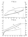
- the curve U f (T) is plotted for different charge rates% Cn of the battery, and the kref values obtained are plotted to plot the curve 11 of the battery. figure 1 .
- kref used in this calculation is that given by curve 11 of the figure 1 for each state of charge.
- the curve 12 is plotted with a kref coefficient which is not constant in the field of charge rates less than or equal to 55% of Cn, and which is constant and equal to k for charge rates greater than 55% Cn.
- the initial temperature battery of 21 ° C ( figure 4 ) is charged at a rate of 1.5lc. Its internal temperature (curve 40) and its voltage (curve 41) are periodically measured. It can be seen that for high-capacity accumulators, the increase in the charging voltage is low.
- the coefficient k is constant.
- the curve of the corrected voltage Uc is only significantly exploitable in the field of charge rates greater than 55% of Cn.
- the charge is stopped when Uc is at least Us, that is at least 8,087V. It is verified that the charge rate reached by the battery is 75% of Cn.
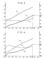
- the charge is reproduced under conditions similar to Example 1, except that the initial temperature is 0 ° C. ( figure 5 ).
- the charge is stopped when Uc is at least 8,087V and the charge rate reached by the battery is 75% of Cn.
- the charge is reproduced under conditions similar to Example 1, except that the initial temperature is -10 ° C. ( figure 6 ).
- the charge is stopped when Uc is at least 8,087V and the charge rate reached by the battery is 75% of Cn.
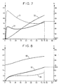
- the charge is reproduced under conditions similar to Example 1, except that the initial temperature is -20 ° C. ( figure 7 ).
- the charge is stopped when Uc is at least 8,087V and the charge rate reached by the battery is 75% of Cn.
- the voltage threshold Us varies according to the chosen charging regime of 0.70 volts per unit of current expressed in Ic, the reference temperature Tc remaining unchanged.
- the transition from a 1.5lc regime to a 0.75lc led to lowering the Us threshold of 0.525V, from 8,087V to 7,562V
- the charge is stopped when Uc is at least 7,562V and the charge rate reached by the battery is 75% of Cn.
Landscapes
- Engineering & Computer Science (AREA)
- Power Engineering (AREA)
- Secondary Cells (AREA)
- Battery Electrode And Active Subsutance (AREA)
Claims (6)
- Verfahren zur Prüfung der Schnell-Ladung eines industriellen Akkumulators mit alkalischem Elektrolyt vom "wartungsfreien" oder "dichten" Typ mit einer Nennkapazität Cn, einer Spannung U und einer Innentemperatur T, dadurch gekennzeichnet, dass die Abschaltung der Ladung mit einer 55% Cn überschreitenden Ladestärke wie folgt durchgeführt wird:- Man legt eine Spannungsschwelle Us fest, die einer gewünschten Endladestärke des Akkumulators entspricht;- Man misst die Spannung U und die Temperatur T des Akkumulators;- Man berechnet eine korrigierte Spannung Uc anhand folgender Formel:

wobei die Spannungen in Volt ausgedrückt werden, wobei Tc eine willkürlich gewählte Referenztemperatur ist, und k ist ein konstanter Koeffizient, der in Volt pro Temperatureinheit ausgedrückt wird;- Man vergleicht Uc mit der Spannungsschwelle Us und man schaltet die Ladung ab, wenn Uc mindestens gleich Us ist. - Verfahren nach Anspruch 1, in dem der Koeffizient k wie folgt definiert wird:- Man zieht die Gerade U=f(T) für jeden Wert des Ladegrads mittels der Ladekurven des Akkumulators, die mit mindestens zwei verschiedenen Ausgangstemperaturen festgelegt sind;- Man misst die Neigung der Geraden im Bereich der Ladestärken, die 55% Cn überschreiten, wobei die Neigung gleich k ist.
- Verfahren nach Anspruch 2, in dem der Koeffizient k für -0,015 V/°C bei 55% Cn überschreitenden Ladestärken gilt.
- Verfahren nach einem der vorhergehenden Ansprüche, in dem die Spannungsschwelle Us wie folgt festgelegt ist:- Man berechnet eine Referenzspannung Uref ab einer Ladekurve des Akkumulators nach der Formel:

wobei kref ein Koeffizient ist, der gleich der Neigung der Geraden U=f(T) ist, die bei Ladestärken unter oder von gleich 55% Cn variabel und dann bei Ladestärken über 55% Cm konstant ist.- Man legt die Gleichung der Variationsgeraden von Uref in Abhängigkeit von der Ladestärke fest;- Man berechnet die Schwelle Us ab der Gleichung für einen gewünschten Endladegrad oberhalb von 55% Cn. - Verfahren nach Anspruch 4, in dem die Schwelle Us vom Ladebetrieb in Höhe von 0,70 V pro in Ic, ausgedrückter Stromeinheit abhängt, wobei Ic der zur Entladung der Nennkapazität Cn des Akkumulators in einer Stunde erforderliche Strom ist.
- Verfahren nach einem der vorhergehenden Ansprüche, in dem die Referenztemperatur Tc als 0°C gilt, wobei die Referenzspannung Uref durch folgende Formel berechnet wird:

und die korrigierte Spannung durch folgende Formel berechnet wird:
Applications Claiming Priority (2)
| Application Number | Priority Date | Filing Date | Title |
|---|---|---|---|
| FR9809914A FR2782417B1 (fr) | 1998-08-13 | 1998-08-13 | Procede de controle de la charge rapide d'accumulateur industriel a electrolyte alcalin |
| FR9809914 | 1998-08-13 |
Publications (2)
| Publication Number | Publication Date |
|---|---|
| EP0980130A1 EP0980130A1 (de) | 2000-02-16 |
| EP0980130B1 true EP0980130B1 (de) | 2008-04-16 |
Family
ID=9529317
Family Applications (1)
| Application Number | Title | Priority Date | Filing Date |
|---|---|---|---|
| EP99401903A Expired - Lifetime EP0980130B1 (de) | 1998-08-13 | 1999-07-26 | Schnellladesteuerungsverfahren für einen industriellen Akkumulator mit alkalischem Elektrolyt |
Country Status (5)
| Country | Link |
|---|---|
| US (1) | US6094032A (de) |
| EP (1) | EP0980130B1 (de) |
| JP (1) | JP2000067927A (de) |
| DE (1) | DE69938522T2 (de) |
| FR (1) | FR2782417B1 (de) |
Families Citing this family (7)
| Publication number | Priority date | Publication date | Assignee | Title |
|---|---|---|---|---|
| JP4340020B2 (ja) * | 2001-04-10 | 2009-10-07 | パナソニック株式会社 | 無人搬送車用二次電池の充電制御方法 |
| EP1328055B1 (de) * | 2002-01-10 | 2012-07-25 | Honda Giken Kogyo Kabushiki Kaisha | System zur Ladesteuerung einer Sekundärbatterie |
| JP3879981B2 (ja) | 2002-01-17 | 2007-02-14 | 本田技研工業株式会社 | 二次電池の充電制御装置 |
| JP4161854B2 (ja) * | 2003-09-02 | 2008-10-08 | ソニー株式会社 | 電池残容量算出方法、電池残容量算出装置および電池残容量算出プログラム |
| FR2950742B1 (fr) | 2009-09-29 | 2011-10-07 | Commissariat Energie Atomique | Procede de charge et procede de determination d'un critere de fin de charge d'une batterie a base de nickel |
| US9252463B2 (en) * | 2010-10-21 | 2016-02-02 | Chervon (Hk) Limited | Battery charging system having multiple charging modes |
| RU2621694C9 (ru) * | 2015-07-01 | 2017-11-09 | Российская Федерация, от имени которой выступает Министерство обороны Российской Федерации | Способ эксплуатации никель-водородных аккумуляторных батарей системы электропитания летательных аппаратов |
Family Cites Families (3)
| Publication number | Priority date | Publication date | Assignee | Title |
|---|---|---|---|---|
| US5315228A (en) * | 1992-01-24 | 1994-05-24 | Compaq Computer Corp. | Battery charge monitor and fuel gauge |
| US5703468A (en) * | 1995-03-17 | 1997-12-30 | Petrillo; Gino A. | Electrical charge control apparatus and method for photovoltaic energy conversion systems |
| FR2739724B1 (fr) * | 1995-10-05 | 1997-11-14 | Accumulateurs Fixes | Procede de charge de batteries nickel-cadmium etanches |
-
1998
- 1998-08-13 FR FR9809914A patent/FR2782417B1/fr not_active Expired - Fee Related
-
1999
- 1999-07-26 DE DE69938522T patent/DE69938522T2/de not_active Expired - Lifetime
- 1999-07-26 EP EP99401903A patent/EP0980130B1/de not_active Expired - Lifetime
- 1999-08-10 JP JP11226548A patent/JP2000067927A/ja active Pending
- 1999-08-12 US US09/373,238 patent/US6094032A/en not_active Expired - Lifetime
Also Published As
| Publication number | Publication date |
|---|---|
| DE69938522D1 (de) | 2008-05-29 |
| FR2782417B1 (fr) | 2000-09-15 |
| US6094032A (en) | 2000-07-25 |
| FR2782417A1 (fr) | 2000-02-18 |
| EP0980130A1 (de) | 2000-02-16 |
| DE69938522T2 (de) | 2009-07-09 |
| JP2000067927A (ja) | 2000-03-03 |
Similar Documents
| Publication | Publication Date | Title |
|---|---|---|
| EP1774353B1 (de) | Verfahren zur akkuspeicherverwaltung | |
| EP3237258B1 (de) | Verfahren zur energieverwaltung einer wiederaufladbaren traktionsbatterie eines hybridfahrzeugs | |
| EP2122379B1 (de) | Verfahren zur bestimmung der entladungsendschwelle eines akkus | |
| EP2483962B1 (de) | Verfahren zur aufladung einer nickelbatterie und verfahren zur definition eines kriteriums für das ende des ladevorgangs für eine nickel-batterie | |
| EP2878034B1 (de) | Fahrzeug mit einer batterie und einem mittel zur bestimmung der maximal zulässigen leistung der batterie sowie entsprechendes verfahren | |
| WO2011051575A2 (fr) | Procédé de charge ou de décharge d'une batterie pour déterminer la fin de charge ou de décharge en fonction de mesures de courant et de température | |
| FR2803105A1 (fr) | Procede de charge rapide d'une batterie d'accumulateurs | |
| EP1766718A1 (de) | Verfahren zum laden einer lithiumionen-batterie mit einer negativen elektrode | |
| EP2309615B1 (de) | System und Verfahren zur Steuerung des Aufladevorgangs einer Batterie | |
| EP0980130B1 (de) | Schnellladesteuerungsverfahren für einen industriellen Akkumulator mit alkalischem Elektrolyt | |
| EP4009480B1 (de) | Verfahren zur steuerung des ladezustands eines akkumulators für eine optimierte alterung | |
| FR2636479A1 (fr) | Procede de charge ultrarapide pour accumulateur cadmium-nickel etanche | |
| EP1243935A1 (de) | Entladungssteuerungsverfahren für eine Batterie von elektrochemischen Sekundärgeneratoren | |
| FR2907272A1 (fr) | Procede de gestion de la fin de decharge d'une batterie rechargeable | |
| EP4081817A1 (de) | Verfahren zum identifizieren des beginns der beschleunigung der verschlechterung des gesundheitszustands eines packs von wiederaufladbaren batterien | |
| EP0863599B1 (de) | Ladeverfahren für wartungsfreie Nickelmetallhydridbatterien | |
| EP3220471B1 (de) | Verfahren zum laden einer batterie von elektrochemischen akkumulatoren und vorrichtung zur kontrolle des ladevorgangs | |
| EP3087654A1 (de) | Verfahren und system zur batterieverwaltung für kraftfahrzeuge | |
| WO2012140176A1 (fr) | Procede de charge optimal d'un accumulateur electrochimique | |
| FR2798528A1 (fr) | Systeme d'alimentation en courant electrique a plusieurs accumulateurs d'energie | |
| EP4435452A1 (de) | Verfahren zur schätzung des ladezustandes einer batterie eines systems mit geringem stromverbrauch und system zur durchführung des verfahrens | |
| EP4373698A1 (de) | Fahrzeug mit einem akkumulator und mitteln zur bestimmung einer maximal akzeptablen leistung für den akkumulator während einer ladephase | |
| FR2640817A1 (en) | Ultra-fast charger for electrical accumulator | |
| FR2808927A1 (fr) | Accumulateur rechargeable |
Legal Events
| Date | Code | Title | Description |
|---|---|---|---|
| PUAI | Public reference made under article 153(3) epc to a published international application that has entered the european phase |
Free format text: ORIGINAL CODE: 0009012 |
|
| AK | Designated contracting states |
Kind code of ref document: A1 Designated state(s): DE FR GB |
|
| AX | Request for extension of the european patent |
Free format text: AL;LT;LV;MK;RO;SI |
|
| 17P | Request for examination filed |
Effective date: 20000816 |
|
| AKX | Designation fees paid |
Free format text: DE FR GB |
|
| RAP1 | Party data changed (applicant data changed or rights of an application transferred) |
Owner name: SAFT FINANCE S.AE.R.L. |
|
| GRAP | Despatch of communication of intention to grant a patent |
Free format text: ORIGINAL CODE: EPIDOSNIGR1 |
|
| RIN1 | Information on inventor provided before grant (corrected) |
Inventor name: BARIAND, MARC Inventor name: BERLUREAU, THIERRY Inventor name: LISKA, JEAN-LOUIS |
|
| RAP1 | Party data changed (applicant data changed or rights of an application transferred) |
Owner name: SAFT FINANCE S.A.R.L. |
|
| RAP1 | Party data changed (applicant data changed or rights of an application transferred) |
Owner name: SAFT GROUPE SA |
|
| GRAS | Grant fee paid |
Free format text: ORIGINAL CODE: EPIDOSNIGR3 |
|
| GRAA | (expected) grant |
Free format text: ORIGINAL CODE: 0009210 |
|
| AK | Designated contracting states |
Kind code of ref document: B1 Designated state(s): DE FR GB |
|
| REF | Corresponds to: |
Ref document number: 69938522 Country of ref document: DE Date of ref document: 20080529 Kind code of ref document: P |
|
| PLBE | No opposition filed within time limit |
Free format text: ORIGINAL CODE: 0009261 |
|
| STAA | Information on the status of an ep patent application or granted ep patent |
Free format text: STATUS: NO OPPOSITION FILED WITHIN TIME LIMIT |
|
| 26N | No opposition filed |
Effective date: 20090119 |
|
| PGFP | Annual fee paid to national office [announced via postgrant information from national office to epo] |
Ref country code: GB Payment date: 20120629 Year of fee payment: 14 |
|
| GBPC | Gb: european patent ceased through non-payment of renewal fee |
Effective date: 20130726 |
|
| PG25 | Lapsed in a contracting state [announced via postgrant information from national office to epo] |
Ref country code: GB Free format text: LAPSE BECAUSE OF NON-PAYMENT OF DUE FEES Effective date: 20130726 |
|
| PGFP | Annual fee paid to national office [announced via postgrant information from national office to epo] |
Ref country code: DE Payment date: 20140724 Year of fee payment: 16 |
|
| REG | Reference to a national code |
Ref country code: DE Ref legal event code: R119 Ref document number: 69938522 Country of ref document: DE |
|
| PG25 | Lapsed in a contracting state [announced via postgrant information from national office to epo] |
Ref country code: DE Free format text: LAPSE BECAUSE OF NON-PAYMENT OF DUE FEES Effective date: 20160202 |
|
| REG | Reference to a national code |
Ref country code: FR Ref legal event code: PLFP Year of fee payment: 18 |
|
| PGFP | Annual fee paid to national office [announced via postgrant information from national office to epo] |
Ref country code: FR Payment date: 20160707 Year of fee payment: 18 |
|
| REG | Reference to a national code |
Ref country code: FR Ref legal event code: ST Effective date: 20180330 |
|
| PG25 | Lapsed in a contracting state [announced via postgrant information from national office to epo] |
Ref country code: FR Free format text: LAPSE BECAUSE OF NON-PAYMENT OF DUE FEES Effective date: 20170731 |