EP0980013A2 - Abdichtung für Verbindungsgehäuse für Unterwasserkabel - Google Patents
Abdichtung für Verbindungsgehäuse für Unterwasserkabel Download PDFInfo
- Publication number
- EP0980013A2 EP0980013A2 EP99401985A EP99401985A EP0980013A2 EP 0980013 A2 EP0980013 A2 EP 0980013A2 EP 99401985 A EP99401985 A EP 99401985A EP 99401985 A EP99401985 A EP 99401985A EP 0980013 A2 EP0980013 A2 EP 0980013A2
- Authority
- EP
- European Patent Office
- Prior art keywords
- anchorage
- casing
- sealing surface
- ring
- loading ring
- Prior art date
- Legal status (The legal status is an assumption and is not a legal conclusion. Google has not performed a legal analysis and makes no representation as to the accuracy of the status listed.)
- Granted
Links
Images


Classifications
-
- G—PHYSICS
- G02—OPTICS
- G02B—OPTICAL ELEMENTS, SYSTEMS OR APPARATUS
- G02B6/00—Light guides; Structural details of arrangements comprising light guides and other optical elements, e.g. couplings
- G02B6/44—Mechanical structures for providing tensile strength and external protection for fibres, e.g. optical transmission cables
- G02B6/4401—Optical cables
- G02B6/4415—Cables for special applications
- G02B6/4427—Pressure resistant cables, e.g. undersea cables
- G02B6/4428—Penetrator systems in pressure-resistant devices
-
- H—ELECTRICITY
- H02—GENERATION; CONVERSION OR DISTRIBUTION OF ELECTRIC POWER
- H02G—INSTALLATION OF ELECTRIC CABLES OR LINES, OR OF COMBINED OPTICAL AND ELECTRIC CABLES OR LINES
- H02G15/00—Cable fittings
- H02G15/08—Cable junctions
- H02G15/10—Cable junctions protected by boxes, e.g. by distribution, connection or junction boxes
- H02G15/12—Cable junctions protected by boxes, e.g. by distribution, connection or junction boxes for incorporating transformers, loading coils or amplifiers
- H02G15/14—Cable junctions protected by boxes, e.g. by distribution, connection or junction boxes for incorporating transformers, loading coils or amplifiers specially adapted for submarine cables
Definitions
- the present invention relates generally to an apparatus which provides a seal between two surfaces, and specifically to an apparatus which seals the ends of two optical fiber cables inside a casing to prevent damage to optical fibers and optical attenuation when the casing is submerged in water and exposed to hydrogen.
- the present invention is directed at providing a seal at an end of the casing.
- submarine optical cable junctions are known for connecting two cables underwater.
- optical fibers from one cable are physically connected to optical fibers of another cable, disposed underwater, and subjected to water pressure in excess of 10,150 pounds per square inch.
- the submarine optical cable junction typically suffers from problems caused by hydrogen entering into the cable junction that adversely affects the optical fibers in the two cables that are exposed in the cable junction.
- the hydrogen is generated near the cable junction from galvanic corrosion of metal parts, magnetohydrodynamic effects, and microbial activity near the cable junction.
- the hydrogen causes optical loss in the optical fiber, which is known in the art as hydrogen induced attenuation. If hydrogen penetrates a significant distance along the optical fibers, then the hydrogen causes a significant amount of hydrogen induced attenuation in the optical fiber.
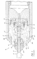
- FIG. 1 shows one end of a prior art cable junction generally indicated as 8 having a cable 10 sealed inside a tubular stainless steel casing 12.
- the cable 10 is connected to another cable similarly sealed inside the casing 12 but not shown in
- the cable junction 8 is substantially symmetrical, and for the purpose of this discussion only one end is shown and described herein.
- the cable 10 typically has a capillary tube 16 which contains a water-blocking compound therein.
- the water-blocking compound may contain a hydrogen-absorbing compound, which may delay the onset of hydrogen induced attenuation depending upon the absorption capacity of the compound, the degree to which the compound fills the capillary tube 16, and the applied hydrogen pressure. However, hydrogen inevitably enters the capillary tube 16.
- the cable 10 comprises a protective sheath 14, a power conductor 15, a capillary tube 16, within which are housed the optical fibers (not shown), and strength members 17.
- the cable 10 is secured to the anchorage 20 by clamping the strength members 17 to the anchorage 20 via a ferrule 22, a retaining washer 23, and a retaining nut 24.
- the mounting block 21 provides support for the capillary tube 16.
- the mounting block 21 is held against the anchorage 20 by stopper screws 31.
- the anchorage 20 is in turn fixed relative to the casing 12 via the anchorage/casing threaded joint 33 and the loading ring 38.
- the loading ring 38 is threaded on the anchorage 20 by engaging a torque wrench (not shown) in blind holes 38a, for turning the loading ring 38 on the threads 85.
- the protective sheath 14 is removed from the cable 10 to expose the power conductor 15.
- a compression body 26 and a sleeve portion 27 are compressed against the power conductor 15 and the anchorage 20 by threaded cap nut 28 to secure cable 10 to anchorage 20.
- the prior art suffers from problems related to hydrogen entering into the cable junction 8.
- One such problem is that the anchorage/casing threaded joint 33 does not provide an effective seal with regard to hydrogen. Therefore, hydrogen can leak into the casing 12 between the casing 12 and the loading ring 38 at a junction generally indicated as "A" in FIG. 1.
- hydrogen can leak into the casing 12 between the anchorage 20 and the loading ring 38 at a junction generally indicated as "B” in FIG. 1.
- the present invention provides a cable junction featuring a seal between a casing and an anchorage that prevents hydrogen from entering the casing.
- the invention includes a combination of an anchorage/casing seal ring, an anchorage loading ring, and a casing loading ring.
- the anchorage loading ring compresses one part of the anchorage/casing seal ring against a sealing surface of the anchorage.
- the casing loading ring compresses another part of the anchorage/casing seal ring against a sealing surface of the casing.
- the sealing surface of the anchorage has a circular anchorage ridge
- the sealing surface of the casing has a circular casing ridge, both ridges being embedded into the anchorage/casing seal ring when properly assembled.
- One important advantage of the invention is that the seal prevents hydrogen from entering between the anchorage and the casing, and reduces the undesirable affects caused by hydrogen induced attenuation in the optical fiber.
- the seal of the present invention which generally comprises two loading rings and a seal ring.
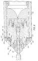
- FIG. 2 shows a cable junction 100 that is the subject of the present nvention for connecting two optical cables that will be submerged underwater, one cable is indicated as 110.
- the cable junction 100 is similar to the cable junction 8 in FIG. 1 in many ways. The following discussion focuses on the differences between FIG. 1 and FIG. 2, with respect to the anchorage/casing joint that is the point of novelty of the invention.
- the cable junction 100 has a casing 130, an anchorage 120, a casing loading ring 150, an anchorage loading ring 145 and a seal ring 140.
- the casing 130 has a casing sealing surface 153.
- the casing sealing surface 153 includes a casing circular ridge 260.
- the anchorage 120 is arranged in the casing 130, and has an anchorage sealing surface 157.
- the anchorage sealing surface 157 includes an anchorage circular ridge 263.
- the anchorage 120 is rotatably coupled to the casing 130 by an anchorage/casing threaded joint 133.
- the casing loading ring 150 has a casing loading ring sealing surface 150a.
- the anchorage loading ring 145 has an anchorage loading ring sealing surface 145a.
- the seal ring 140 is arranged between the casing sealing surface 153 and the casing loading ring sealing surface 150a, and also arranged between the anchorage sealing surface 157 and the anchorage loading ring sealing surface 145a for preventing hydrogen from entering the cable junction 100.
- the seal ring 140 is preferably made from a metal material such as copper however, the scope of the invention is not intended to be limited to any particular material. Annealed copper (UNS 10200) is an appropriate choice for the seal ring 140.
- the anchorage loading ring 145 is rotatably coupled to the anchorage 120 by an anchorage loading ring threaded joint 134a for sealably compressing the seal ring 140 between the anchorage sealing surface 157 and the anchorage loading ring sealing surface 145a.
- the casing loading ring 150 is rotatably coupled to the anchorage 120 by the casing loading ring threaded joint 134b for sealably compressing the seal ring 140 between the casing sealing surface 153 and the casing loading ring sealing surface 150a for preventing hydrogen from entering the cable junction 100.
- the cable junction 100 is formed as follows.
- the anchorage 120 is attached to the casing 130 by engaging the threads of the casing 130 and the threads of the anchorage 120 to form the anchorage/casing threaded joint 133.
- the seal ring 140 is placed around the anchorage 120 and against the sealing surfaces 153, 157.
- Anchorage loading ring 145 is then threaded onto the anchorage 120 by engaging the loading ring threads 185 with the threads 146 (shown in FIGS. 3 and 3S) of the anchorage loading ring 145 until the anchorage loading ring 145 compresses the seal ring 140 firmly against anchorage sealing surface 157 such that the circular ridge 263 is fully embedded in the seal ring 140.
- the casing loading ring 150 is threaded onto the anchorage 120 by engaging the loading ring threads 185 with the threads 151 (shown in FIGS. 4 and 4S) of the casing loading ring 150 until the casing loading ring 150 compresses the seal ring 140 firmly against the casing sealing surface 153 such that the circular ridge 260 is fully embedded in the seal ring 140.
- the anchorage sealing surface 157 is shown in line with the casing sealing surface 153 so that when the seal ring 140 is installed, the seal ring major surfaces 187 (discussed below and shown in FIGS. 5 and 6) remain substantially flat.
- the scope of the invention is not intended to be limited to the sealing surfaces 153, 157 being in line with each other.
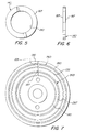
- FIG. 3 shows the anchorage loading ring 145. Also shown are the anchorage loading ring threads 146 for engaging the loading ring threads 185 of the anchorage 120.
- FIG. 4 shows the casing loading ring 150. Also shown are the casing loading ring threads 151 for engaging the loading ring threads 185 of the anchorage 120.
- FIGS. 5 and 6 show the seal ring 140 having opposing flat major surfaces 187 and an aperture 190 for permitting the seal ring 140 to be placed around the anchorage 120.
- the aperture 190 is large enough to permit the seal ring 140 to slide over the loading ring threads 185.
- the seal ring 140 is preferably made from a metal comprising copper.
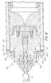
- FIG. 7 shows the casing sealing surface 153 and the anchorage sealing surface 157 in more detail.
- FIG. 7 shows the casing circular ridge 260, which has a sharp leading edge 265, and also shows the anchorage circular ridge 263, which has a sharp leading edge 267, both ridges 260, 263 for embedding into the seal ring 140. It is estimated that an embodiment of the cable junction 100 for an optical fiber cable 110 having a diameter of 14mm will require a load of approximately 180 kN to properly embed the circular ridges 260, 263 having sharp leading edge 265 or 267 in the seal ring 140.
- FIG. 8 shows an embodiment of the present invention where the sealing surfaces 153, 157 are not in line with each other.
- the seal ring 140 deforms under the force applied by the press machine so that the major surfaces 187 of the seal ring 140 are not flat.
- the ability to seal the anchorage/casing joint when the sealing surfaces 153, 157 are not in line with each other is particularly important since the casing 130 and anchorage 120 are not often in alignment, and bringing them into alignment is difficult.
- the preferred material for the casing 130 and the loading rings 145, 150 is Z6 CND 16-04-01 (AFNOR).
- a suitable material for the casing is BS 970 431S29 (SAE/AISI 431).
- the seal must be capable of accommodating variation in the relative position of the anchorage 120 and the casing 130.
- a 1/16" thick copper seal ring 140 is placed over the two sharp leading edges 265, 267 and deformed on to the sealing surfaces 153, 157 by the loading rings 145, 150 screwed onto the anchorage 120. This is necessary to allow for the tolerance in position of the casing 130 and anchorage 120 subsequent to fitting of the casing 130.
- the casing loading ring 150 may be profiled to maintain the existing outer shape of the 14 mm joint, and also provides the lock nut action to the casing 130 via the seal ring 140. To achieve this locking action, it is important that the sharp leading edges 265, 267 are fully embedded into the seal ring 140.
- the cable tension is transferred from the strand termination through the anchorage 120 and then to the casing 130, via the M70 x 2 thread form (threaded joint 133).
- the casing loading ring 150 is tightened so that the threaded joint 133 is in tension. Therefore, when a load is applied to the cable 110 there will be no free play in the threaded joint 133, and so the anchorage 120 and casing 130 strain together. Further, the pre-load applied to the sharp leading edge 265 will not be influenced by the application of cable tension, as the seal ring 140 is not included in the load transfer path.
- the material specified for a prior art 14 mm anchorage 20, casing 12 and loading ring 38 is Z6 CND 16-04-01 (AFNOR).
- the mechanical properties for this material are not known and thus the safety factors cannot be determined.
- a suitable material for these components is BS 970 431S29 (U.S. equivalent SAE/AISI 431) which is a heat treatable martensitic stainless steel with a yield stress of 800 MPa when hardened and tempered at 600°C. Therefore with this material, a minimum safety factor on yield of 1 results, which will be more than adequate, as we have considered a worst case scenario, and further the joint 100 cannot be "over pressurized" in service.
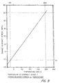
- the copper seal ring 140 is restricted from free expansion or contraction in the axial direction. Therefore, a temperature change either during service or molding will introduce thermal stresses in the seal ring 140.
- the thermal stresses induced within the seal ring 140 as a result of temperature cycling can be determined as follows.
- the cross-sectional areas of the copper seal ring 140 and its adjacent steel components are given by equations 5 and 6, respectively.
Landscapes
- Physics & Mathematics (AREA)
- General Physics & Mathematics (AREA)
- Optics & Photonics (AREA)
- Engineering & Computer Science (AREA)
- Power Engineering (AREA)
- Mechanical Coupling Of Light Guides (AREA)
- Cable Accessories (AREA)
- Laying Of Electric Cables Or Lines Outside (AREA)
- Structure And Mechanism Of Cameras (AREA)
- Light Guides In General And Applications Therefor (AREA)
- Processing Of Terminals (AREA)
Applications Claiming Priority (2)
| Application Number | Priority Date | Filing Date | Title |
|---|---|---|---|
| US09/131,645 US6028974A (en) | 1998-08-10 | 1998-08-10 | Seal for underwater cable joint |
| US131645 | 1998-08-10 |
Publications (3)
| Publication Number | Publication Date |
|---|---|
| EP0980013A2 true EP0980013A2 (de) | 2000-02-16 |
| EP0980013A3 EP0980013A3 (de) | 2002-03-20 |
| EP0980013B1 EP0980013B1 (de) | 2004-02-04 |
Family
ID=22450381
Family Applications (1)
| Application Number | Title | Priority Date | Filing Date |
|---|---|---|---|
| EP99401985A Expired - Lifetime EP0980013B1 (de) | 1998-08-10 | 1999-08-05 | Abdichtung für Verbindungsgehäuse für Unterwasserkabel |
Country Status (5)
| Country | Link |
|---|---|
| US (1) | US6028974A (de) |
| EP (1) | EP0980013B1 (de) |
| JP (1) | JP3281607B2 (de) |
| AT (1) | ATE259110T1 (de) |
| DE (1) | DE69914547T2 (de) |
Cited By (5)
| Publication number | Priority date | Publication date | Assignee | Title |
|---|---|---|---|---|
| EP1059549A1 (de) * | 1999-06-01 | 2000-12-13 | Alcatel | Unterwassergehäuse für ein optisches Unterseekabel |
| EP2130079A4 (de) * | 2007-03-16 | 2011-05-18 | 3M Innovative Properties Co | Faseroptische kabeleinlasseinrichtung und telekommunikationsgehäusesystem |
| CN105629412A (zh) * | 2016-03-21 | 2016-06-01 | 中天科技海缆有限公司 | 一种海底光缆与陆地光缆连接装置及其连接方法 |
| CN106291840A (zh) * | 2016-10-21 | 2017-01-04 | 长沙湘计海盾科技有限公司 | 用于拖曳声呐系统的可弯曲式水密连接器及其装配方法 |
| CN114622868A (zh) * | 2020-12-10 | 2022-06-14 | 中国科学院沈阳自动化研究所 | 一种水下密封关节 |
Families Citing this family (16)
| Publication number | Priority date | Publication date | Assignee | Title |
|---|---|---|---|---|
| FR2782172B1 (fr) * | 1998-08-04 | 2001-11-30 | Pouyet Sa | Dispositif d'entree de cable a fibres optiques |
| US6584253B2 (en) | 2001-02-02 | 2003-06-24 | Tyco Telecommunications (Us) Inc. | Sealed cable connection |
| US7278789B2 (en) | 2005-09-08 | 2007-10-09 | Tyco Telecommunications (Us) Inc. | Undersea equipment housing with molded terminations |
| ES2764968T3 (es) * | 2008-04-09 | 2020-06-05 | Corning Res & Dev Corp | Dispositivo de entrada de cable de telecomunicaciones |
| CN101615775A (zh) * | 2008-06-24 | 2009-12-30 | 3M创新有限公司 | 通信线缆引入装置 |
| US8361746B2 (en) * | 2008-07-24 | 2013-01-29 | Brookhaven Science Associates, Llc | Methods for detection of methyl-CpG dinucleotides |
| WO2010014476A2 (en) | 2008-08-01 | 2010-02-04 | 3M Innovative Properties Company | Optical fiber cable inlet device with integral optical device |
| US7906727B2 (en) * | 2008-08-26 | 2011-03-15 | Oceaneering International, Inc. | Umbilical bullet connector |
| EP2447750A1 (de) * | 2010-10-27 | 2012-05-02 | Alcatel Lucent | Anordnung mit mindestens einer Glasfaser und Montagevorrichtung |
| EP3430456B1 (de) | 2016-03-17 | 2024-05-01 | Ormond Energy Innovations Inc. | Schützender glasfaserabschluss, system und verfahren zur verwendung davon |
| RU2631408C1 (ru) * | 2016-06-14 | 2017-09-21 | Российская Федерация, от имени которой выступает Министерство обороны Российской Федерации | Устройство подводное для оптоэлектронного оборудования (варианты) |
| US10802239B2 (en) * | 2016-07-07 | 2020-10-13 | Afl Telecommunications Llc | Optical fiber trunk cable breakout canisters and assemblies |
| US11404815B2 (en) | 2017-10-30 | 2022-08-02 | Ormond Energy Innovations Inc. | Sealed connector with triggered mating and method of using same |
| CN111381331A (zh) * | 2018-12-29 | 2020-07-07 | 中天海洋系统有限公司 | 光缆分支接头盒及其安装方法 |
| CN110445086B (zh) * | 2019-09-16 | 2020-09-08 | 广东电网有限责任公司 | 一种电缆中间接头的密封装置 |
| CN112510638B (zh) * | 2020-11-09 | 2021-12-31 | 广州海洋地质调查局 | 一种光电复合海缆耐压防水接头 |
Family Cites Families (7)
| Publication number | Priority date | Publication date | Assignee | Title |
|---|---|---|---|---|
| GB643550A (en) * | 1948-03-22 | 1950-09-20 | Submarine Cables Ltd | Improvements in and relating to sealing devices for submarine electric cables |
| FR2433252A1 (fr) * | 1978-08-11 | 1980-03-07 | Cit Alcatel | Dispositif de raccordement d'un cable coaxial de ligne a un dispositif immerge |
| FR2519149B1 (fr) * | 1981-12-30 | 1985-07-26 | Cables De Lyon Geoffroy Delore | Dispositif de jonction des extremites de deux cables sous-marins a fibres optiques et son procede de fabrication |
| IT1176134B (it) * | 1984-04-27 | 1987-08-12 | Pirelli Cavi Spa | Cavo a fibre ottiche munito di protezione contro l'assorbimento di idrogeno gassoso da parte delle fibre ottiche |
| FR2607939B1 (fr) * | 1986-12-05 | 1989-02-03 | Cables De Lyon Geoffroy Delore | Boite de raccordement pour cables a fibres optiques |
| IT1264902B1 (it) * | 1993-06-29 | 1996-10-17 | Pirelli Cavi Spa | Composizione idrogeno-assorbente per cavi a fibre ottiche e cavo a fibre ottiche includente la suddetta composizione |
| FR2733843B1 (fr) * | 1995-05-03 | 1997-05-30 | Alcatel Submarcom | Dispositif organiseur de connexion de cables a fibres optiques et boite de jonction de cables optiques |
-
1998
- 1998-08-10 US US09/131,645 patent/US6028974A/en not_active Expired - Fee Related
- 1998-11-18 JP JP32761398A patent/JP3281607B2/ja not_active Expired - Fee Related
-
1999
- 1999-08-05 EP EP99401985A patent/EP0980013B1/de not_active Expired - Lifetime
- 1999-08-05 DE DE69914547T patent/DE69914547T2/de not_active Expired - Fee Related
- 1999-08-05 AT AT99401985T patent/ATE259110T1/de not_active IP Right Cessation
Cited By (7)
| Publication number | Priority date | Publication date | Assignee | Title |
|---|---|---|---|---|
| EP1059549A1 (de) * | 1999-06-01 | 2000-12-13 | Alcatel | Unterwassergehäuse für ein optisches Unterseekabel |
| EP2130079A4 (de) * | 2007-03-16 | 2011-05-18 | 3M Innovative Properties Co | Faseroptische kabeleinlasseinrichtung und telekommunikationsgehäusesystem |
| CN105629412A (zh) * | 2016-03-21 | 2016-06-01 | 中天科技海缆有限公司 | 一种海底光缆与陆地光缆连接装置及其连接方法 |
| CN105629412B (zh) * | 2016-03-21 | 2018-11-06 | 中天科技海缆有限公司 | 一种海底光缆与陆地光缆连接装置及其连接方法 |
| CN106291840A (zh) * | 2016-10-21 | 2017-01-04 | 长沙湘计海盾科技有限公司 | 用于拖曳声呐系统的可弯曲式水密连接器及其装配方法 |
| CN114622868A (zh) * | 2020-12-10 | 2022-06-14 | 中国科学院沈阳自动化研究所 | 一种水下密封关节 |
| CN114622868B (zh) * | 2020-12-10 | 2023-09-08 | 中国科学院沈阳自动化研究所 | 一种水下密封关节 |
Also Published As
| Publication number | Publication date |
|---|---|
| EP0980013B1 (de) | 2004-02-04 |
| EP0980013A3 (de) | 2002-03-20 |
| US6028974A (en) | 2000-02-22 |
| JP3281607B2 (ja) | 2002-05-13 |
| JP2000059979A (ja) | 2000-02-25 |
| DE69914547D1 (de) | 2004-03-11 |
| ATE259110T1 (de) | 2004-02-15 |
| DE69914547T2 (de) | 2004-12-16 |
Similar Documents
| Publication | Publication Date | Title |
|---|---|---|
| US6028974A (en) | Seal for underwater cable joint | |
| US4687293A (en) | Metal-encased light conductor | |
| US5598500A (en) | Fixing, earthing and sealing device for optical cables | |
| US10606000B2 (en) | Optical waveguide feedthrough assembly | |
| US20030063869A1 (en) | Module attachment for securing at least one optical waveguide and methods therefor | |
| EP0235891B1 (de) | Klemmvorrichtung | |
| US5166997A (en) | Cable retention system | |
| JP5159669B2 (ja) | シールド・ケーブルの接続部 | |
| US3922104A (en) | Tension link control device | |
| US20020151209A1 (en) | Cable guide for a sealed box, and a sealing assembly including such a guide | |
| WO2020002111A1 (en) | Anchor sleeve and anchor system | |
| US4189620A (en) | Cable termination device | |
| USH491H (en) | Fiber optic attenuator | |
| US6338579B1 (en) | Fiber optic sleeve assembly for use at a splice junction of a fiber optic cable | |
| US20180216757A1 (en) | Fluid sealing device and power cable line | |
| US5835653A (en) | Termination assembly for an optical fiber cable | |
| US4126498A (en) | Boots for wire rope terminations | |
| JPH08138458A (ja) | 光、電力複合ケーブル | |
| KR20030059048A (ko) | 원형 강관으로 섬유긴장재를 보호한 정착장치 | |
| US20220329010A1 (en) | Compression mechanisms for cable sealing on closures | |
| FI95091C (fi) | Painetiivis muhvi | |
| RU2073292C1 (ru) | Узел заделки грузонесущих элементов троса | |
| US4958856A (en) | Pressure energized sealing joint | |
| KR20260008002A (ko) | 보호 슬리브 시스템 및 조립 방법 | |
| SU1125590A1 (ru) | Волоконно-оптический соединитель |
Legal Events
| Date | Code | Title | Description |
|---|---|---|---|
| PUAI | Public reference made under article 153(3) epc to a published international application that has entered the european phase |
Free format text: ORIGINAL CODE: 0009012 |
|
| AK | Designated contracting states |
Kind code of ref document: A2 Designated state(s): AT BE CH CY DE DK ES FI FR GB GR IE IT LI LU MC NL PT SE |
|
| AX | Request for extension of the european patent |
Free format text: AL;LT;LV;MK;RO;SI |
|
| PUAL | Search report despatched |
Free format text: ORIGINAL CODE: 0009013 |
|
| AK | Designated contracting states |
Kind code of ref document: A3 Designated state(s): AT BE CH CY DE DK ES FI FR GB GR IE IT LI LU MC NL PT SE |
|
| AX | Request for extension of the european patent |
Free format text: AL;LT;LV;MK;RO;SI |
|
| RIC1 | Information provided on ipc code assigned before grant |
Free format text: 7H 02G 15/14 A, 7G 02B 6/44 B |
|
| 17P | Request for examination filed |
Effective date: 20020920 |
|
| AKX | Designation fees paid |
Free format text: AT BE CH CY DE DK ES FI FR GB GR IE IT LI LU MC NL PT SE |
|
| 17Q | First examination report despatched |
Effective date: 20021202 |
|
| GRAP | Despatch of communication of intention to grant a patent |
Free format text: ORIGINAL CODE: EPIDOSNIGR1 |
|
| GRAS | Grant fee paid |
Free format text: ORIGINAL CODE: EPIDOSNIGR3 |
|
| GRAA | (expected) grant |
Free format text: ORIGINAL CODE: 0009210 |
|
| AK | Designated contracting states |
Kind code of ref document: B1 Designated state(s): AT BE CH CY DE DK ES FI FR GB GR IE IT LI LU MC NL PT SE |
|
| PG25 | Lapsed in a contracting state [announced via postgrant information from national office to epo] |
Ref country code: NL Free format text: LAPSE BECAUSE OF FAILURE TO SUBMIT A TRANSLATION OF THE DESCRIPTION OR TO PAY THE FEE WITHIN THE PRESCRIBED TIME-LIMIT Effective date: 20040204 Ref country code: LI Free format text: LAPSE BECAUSE OF FAILURE TO SUBMIT A TRANSLATION OF THE DESCRIPTION OR TO PAY THE FEE WITHIN THE PRESCRIBED TIME-LIMIT Effective date: 20040204 Ref country code: FI Free format text: LAPSE BECAUSE OF FAILURE TO SUBMIT A TRANSLATION OF THE DESCRIPTION OR TO PAY THE FEE WITHIN THE PRESCRIBED TIME-LIMIT Effective date: 20040204 Ref country code: CY Free format text: LAPSE BECAUSE OF FAILURE TO SUBMIT A TRANSLATION OF THE DESCRIPTION OR TO PAY THE FEE WITHIN THE PRESCRIBED TIME-LIMIT Effective date: 20040204 Ref country code: CH Free format text: LAPSE BECAUSE OF FAILURE TO SUBMIT A TRANSLATION OF THE DESCRIPTION OR TO PAY THE FEE WITHIN THE PRESCRIBED TIME-LIMIT Effective date: 20040204 Ref country code: BE Free format text: LAPSE BECAUSE OF FAILURE TO SUBMIT A TRANSLATION OF THE DESCRIPTION OR TO PAY THE FEE WITHIN THE PRESCRIBED TIME-LIMIT Effective date: 20040204 Ref country code: AT Free format text: LAPSE BECAUSE OF FAILURE TO SUBMIT A TRANSLATION OF THE DESCRIPTION OR TO PAY THE FEE WITHIN THE PRESCRIBED TIME-LIMIT Effective date: 20040204 |
|
| REG | Reference to a national code |
Ref country code: GB Ref legal event code: FG4D |
|
| REG | Reference to a national code |
Ref country code: CH Ref legal event code: EP |
|
| REG | Reference to a national code |
Ref country code: IE Ref legal event code: FG4D |
|
| REF | Corresponds to: |
Ref document number: 69914547 Country of ref document: DE Date of ref document: 20040311 Kind code of ref document: P |
|
| PG25 | Lapsed in a contracting state [announced via postgrant information from national office to epo] |
Ref country code: SE Free format text: LAPSE BECAUSE OF FAILURE TO SUBMIT A TRANSLATION OF THE DESCRIPTION OR TO PAY THE FEE WITHIN THE PRESCRIBED TIME-LIMIT Effective date: 20040504 Ref country code: GR Free format text: LAPSE BECAUSE OF FAILURE TO SUBMIT A TRANSLATION OF THE DESCRIPTION OR TO PAY THE FEE WITHIN THE PRESCRIBED TIME-LIMIT Effective date: 20040504 Ref country code: DK Free format text: LAPSE BECAUSE OF FAILURE TO SUBMIT A TRANSLATION OF THE DESCRIPTION OR TO PAY THE FEE WITHIN THE PRESCRIBED TIME-LIMIT Effective date: 20040504 |
|
| PG25 | Lapsed in a contracting state [announced via postgrant information from national office to epo] |
Ref country code: ES Free format text: LAPSE BECAUSE OF FAILURE TO SUBMIT A TRANSLATION OF THE DESCRIPTION OR TO PAY THE FEE WITHIN THE PRESCRIBED TIME-LIMIT Effective date: 20040515 |
|
| NLV1 | Nl: lapsed or annulled due to failure to fulfill the requirements of art. 29p and 29m of the patents act | ||
| PG25 | Lapsed in a contracting state [announced via postgrant information from national office to epo] |
Ref country code: LU Free format text: LAPSE BECAUSE OF NON-PAYMENT OF DUE FEES Effective date: 20040805 Ref country code: IE Free format text: LAPSE BECAUSE OF NON-PAYMENT OF DUE FEES Effective date: 20040805 |
|
| REG | Reference to a national code |
Ref country code: CH Ref legal event code: PL |
|
| PG25 | Lapsed in a contracting state [announced via postgrant information from national office to epo] |
Ref country code: MC Free format text: LAPSE BECAUSE OF NON-PAYMENT OF DUE FEES Effective date: 20040831 |
|
| ET | Fr: translation filed | ||
| PLBE | No opposition filed within time limit |
Free format text: ORIGINAL CODE: 0009261 |
|
| STAA | Information on the status of an ep patent application or granted ep patent |
Free format text: STATUS: NO OPPOSITION FILED WITHIN TIME LIMIT |
|
| 26N | No opposition filed |
Effective date: 20041105 |
|
| REG | Reference to a national code |
Ref country code: IE Ref legal event code: MM4A |
|
| REG | Reference to a national code |
Ref country code: FR Ref legal event code: CD |
|
| PGFP | Annual fee paid to national office [announced via postgrant information from national office to epo] |
Ref country code: DE Payment date: 20070822 Year of fee payment: 9 |
|
| PG25 | Lapsed in a contracting state [announced via postgrant information from national office to epo] |
Ref country code: PT Free format text: LAPSE BECAUSE OF NON-PAYMENT OF DUE FEES Effective date: 20040704 |
|
| PGFP | Annual fee paid to national office [announced via postgrant information from national office to epo] |
Ref country code: GB Payment date: 20070823 Year of fee payment: 9 |
|
| PGFP | Annual fee paid to national office [announced via postgrant information from national office to epo] |
Ref country code: IT Payment date: 20070824 Year of fee payment: 9 |
|
| PGFP | Annual fee paid to national office [announced via postgrant information from national office to epo] |
Ref country code: FR Payment date: 20070812 Year of fee payment: 9 |
|
| GBPC | Gb: european patent ceased through non-payment of renewal fee |
Effective date: 20080805 |
|
| REG | Reference to a national code |
Ref country code: FR Ref legal event code: ST Effective date: 20090430 |
|
| PG25 | Lapsed in a contracting state [announced via postgrant information from national office to epo] |
Ref country code: IT Free format text: LAPSE BECAUSE OF NON-PAYMENT OF DUE FEES Effective date: 20080805 Ref country code: FR Free format text: LAPSE BECAUSE OF NON-PAYMENT OF DUE FEES Effective date: 20080901 Ref country code: DE Free format text: LAPSE BECAUSE OF NON-PAYMENT OF DUE FEES Effective date: 20090303 |
|
| PG25 | Lapsed in a contracting state [announced via postgrant information from national office to epo] |
Ref country code: GB Free format text: LAPSE BECAUSE OF NON-PAYMENT OF DUE FEES Effective date: 20080805 |