EP0979890B1 - Fluidum-Strahl Zwirnvorrichtung und Verfahren - Google Patents
Fluidum-Strahl Zwirnvorrichtung und Verfahren Download PDFInfo
- Publication number
- EP0979890B1 EP0979890B1 EP99304942A EP99304942A EP0979890B1 EP 0979890 B1 EP0979890 B1 EP 0979890B1 EP 99304942 A EP99304942 A EP 99304942A EP 99304942 A EP99304942 A EP 99304942A EP 0979890 B1 EP0979890 B1 EP 0979890B1
- Authority
- EP
- European Patent Office
- Prior art keywords
- air
- twist
- yarn
- orifice
- air channel
- Prior art date
- Legal status (The legal status is an assumption and is not a legal conclusion. Google has not performed a legal analysis and makes no representation as to the accuracy of the status listed.)
- Expired - Lifetime
Links
- 238000000034 method Methods 0.000 title description 10
- 238000003780 insertion Methods 0.000 claims description 4
- 230000037431 insertion Effects 0.000 claims description 4
- 230000002093 peripheral effect Effects 0.000 claims description 4
- 238000004891 communication Methods 0.000 claims description 2
- 239000000835 fiber Substances 0.000 description 4
- 238000011144 upstream manufacturing Methods 0.000 description 4
- 238000010586 diagram Methods 0.000 description 3
- 230000000694 effects Effects 0.000 description 3
- 230000005540 biological transmission Effects 0.000 description 2
- 230000015572 biosynthetic process Effects 0.000 description 2
- 229910001220 stainless steel Inorganic materials 0.000 description 2
- 239000010935 stainless steel Substances 0.000 description 2
- 241001589086 Bellapiscis medius Species 0.000 description 1
- 239000004677 Nylon Substances 0.000 description 1
- 229910052782 aluminium Inorganic materials 0.000 description 1
- XAGFODPZIPBFFR-UHFFFAOYSA-N aluminium Chemical compound [Al] XAGFODPZIPBFFR-UHFFFAOYSA-N 0.000 description 1
- 230000000712 assembly Effects 0.000 description 1
- 238000000429 assembly Methods 0.000 description 1
- 239000002131 composite material Substances 0.000 description 1
- 238000010276 construction Methods 0.000 description 1
- 230000003247 decreasing effect Effects 0.000 description 1
- 230000002950 deficient Effects 0.000 description 1
- 238000006073 displacement reaction Methods 0.000 description 1
- 239000012530 fluid Substances 0.000 description 1
- 238000004519 manufacturing process Methods 0.000 description 1
- 229910052751 metal Inorganic materials 0.000 description 1
- 239000002184 metal Substances 0.000 description 1
- 229920001778 nylon Polymers 0.000 description 1
- 230000010355 oscillation Effects 0.000 description 1
- 230000001681 protective effect Effects 0.000 description 1
- 238000012163 sequencing technique Methods 0.000 description 1
Images


Classifications
-
- D—TEXTILES; PAPER
- D02—YARNS; MECHANICAL FINISHING OF YARNS OR ROPES; WARPING OR BEAMING
- D02G—CRIMPING OR CURLING FIBRES, FILAMENTS, THREADS, OR YARNS; YARNS OR THREADS
- D02G3/00—Yarns or threads, e.g. fancy yarns; Processes or apparatus for the production thereof, not otherwise provided for
- D02G3/22—Yarns or threads characterised by constructional features, e.g. blending, filament/fibre
- D02G3/26—Yarns or threads characterised by constructional features, e.g. blending, filament/fibre with characteristics dependent on the amount or direction of twist
- D02G3/28—Doubled, plied, or cabled threads
- D02G3/286—Doubled, plied, or cabled threads with alternatively "S" and "Z" direction of twist, e.g. Self-twist process
-
- Y—GENERAL TAGGING OF NEW TECHNOLOGICAL DEVELOPMENTS; GENERAL TAGGING OF CROSS-SECTIONAL TECHNOLOGIES SPANNING OVER SEVERAL SECTIONS OF THE IPC; TECHNICAL SUBJECTS COVERED BY FORMER USPC CROSS-REFERENCE ART COLLECTIONS [XRACs] AND DIGESTS
- Y10—TECHNICAL SUBJECTS COVERED BY FORMER USPC
- Y10S—TECHNICAL SUBJECTS COVERED BY FORMER USPC CROSS-REFERENCE ART COLLECTIONS [XRACs] AND DIGESTS
- Y10S57/00—Textiles: spinning, twisting, and twining
- Y10S57/908—Jet interlaced or intermingled
Definitions
- This invention relates to an apparatus for twisting individual strands of yarn and plying these individually twisted strands around each other. More specifically, this twisting action is accomplished by false-twisting, where for a certain yarn length the yarn is twisted a number of turns in one direction and then for another sequential length, it is twisted in the opposite direction.
- the application also discloses yarns produced according to the method and on an apparatus of the type described.
- the apparatus according to the invention is much more economical since only a relatively short piece of each yarn is twisted around its own axis.
- the secondary plying occurs automatically since, through the inserted torque, the twisted yarns in the single yarn twist around each other in the direction of the yarn-torque.
- the twist-inserting apparatus is a simple and unique way of providing a twist-inserting jet of air to the moving yarn which is highly precise and reliable, and easily modified when changes in yarn construction or twist characteristics require.
- twist-inserting apparatus for inserting twist into a multi-stranded, plied yarn. Twist is inserted by twisting a section of a given length of each individual strand around its own axis where the downstream sides of the yarns have twist in one direction and the upstream sides have the same amount of opposite twist. The twist direction is alternated periodically, whereby at twist reversal locations the fibers of the individual yarns are "tacked" by, for example, a fluid jet such as an air-jet entangler.
- an apparatus for inserting twist into a moving strand comprising a first body which has an orifice extending therethrough for permitting passage of a moving yarn, and has an air channel extending therethrough and communicating with the orifice.
- the air channel communicates with the orifice at a tangentially-offset angle to the path of the yarn through the orifice to create a cyclonic air circulation pattern in the orifice to insert a predetermined direction of twist into the yarn as the yarn passes through the orifice.
- the first body is adapted for being inverted relative to, and placed in overlying registration with, a second like body whereby the air channel of the first body inserts one predetermined direction of twist into the yarn and the air channel of the second body inserts another predetermined direction of twist into the yarn.
- the first body is disk-shaped, the orifice extends in an axial direction through the body, and at least a portion of the air channel extends radially through the body.
- the disk includes a plurality of spaced-apart orifices and a plurality of air channels, one of the plurality of air channels communicating with a respective one of the orifices.
- the orifices are clustered in a central area of the body and the air channels extend radially inwardly towards the orifices from a peripheral area of the body.
- At least four symmetrically-spaced orifices are formed in the body, and at least four air channels extend radially-inwardly from a peripheral area of the body into communication with a respective one of the orifices.
- each of the air channels intersects the respective orifices at a right angle to the direction of yarn travel.
- selection means are provided for selecting one or the other of the first body or second body air channels to deliver air to the respective first or second orifice and thereby insert a predetermined direction of twist into the yarn.
- the first body comprises a circular disk having opposed first and second major surfaces.
- the apparatus also includes a top end block and a bottom end block between which the first and second disks are sandwiched, and air supply ports extending through the top end block and communicating with respective air channels in the first and second disks.
- the air channels extend through the thickness of the body and communicate with the opposed first and second major surfaces.
- the air channel communicates with the orifice through a respective air channel nozzle, and the area defined by the opening of the nozzle into the orifice is no more than one/fourth of the area of the orifice.
- the air channel communicates with the orifice through a respective air channel nozzle, and the area defined by the opening of the nozzle into the orifice is about one sixth of the area of the orifice.
- the air channel communicates with the orifice through a respective air channel nozzle, and the width of the nozzle is no more than one half of the width of the air channel.
- the air channel communicates with the orifice through a respective air channel nozzle, and wherein the width of the nozzle is no more than about one third of the width of the air channel.
- an apparatus for inserting twist into a moving strand comprises a first body, which includes an orifice extending therethrough for permitting passage of a moving yarn, an air channel extending therethrough and communicating with the orifice.
- the air channel communicates with the orifice at a tangentially-offset angle to the path of the yarn through the orifice to create a cyclonic air circulation pattern in the orifice to insert a predetermined direction of twist into the yarn as the yarn passes through the orifice.
- a second body is provided, which includes an orifice extending therethrough for permitting passage of a moving yarn, an air channel extending therethrough and communicating with the orifice.
- the air channel communicates with the orifice at a tangentially-offset angle to the path of the yarn through the orifice to create a cyclonic air circulation pattern in the orifice to insert a predetermined direction of twist into the yarn as the yarn passes through the orifice.
- the first body is inverted relative to, and placed in overlying registration with the second body.
- the top and bottom end blocks enclose the first and second bodies.
- the top end block includes air supply ports extending therethrough which communicate with respective air channels in the first and second disks for supplying pressurized air thereto.
- the air channel of the first body therefore inserts one predetermined direction of twist into the yarn and the air channel of the second body inserts another predetermined direction of twist into the yarn.
- the first body and the second body comprise respective first and second disks.
- the first and second disks each have a predetermined thickness defining a air channel dimension.
- the apparatus is adapted to receive first and second disks having different predetermined respective thicknesses for accommodating an air channel having a larger or smaller air flow capacity whereby first and/or second disks can be substituted in the apparatus to increase or decrease the air flow capacity required for a given yarn size, configuration or level of twist insertion.
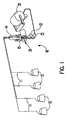
- a fluid-jet false-twisting apparatus is shown schematically in Figure 1 and generally indicated at broad reference numeral 10.
- multi-filament yarns 11 are taken from respective supply packages 12 and passed through a yarn separator 14, a twist-inserting apparatus 15 according to the invention of this application, a rotary air jet assembly 20, where the yarn 11 is plied by the combined action of the twist-inserting apparatus 15 and the rotary air jet assembly 20 in the manner according to the invention as described in this application.
- Air is supplied to the twist-inserting apparatus 15 from a source of pressurized air by means of solenoid valves controlled by mechanical, electromechanical or, preferably, electronic means (not shown).
- the length of the yarn upstream of the twist-inserting apparatus 15 can be less than twice the distance between each twist reversal, and in some applications as low as one-to-one, a substantial advantage over prior art processes.
- the yarns 11, now in plied form, are guided around overfeed drive rolls 22, 23 where the tension on the plied yarns 11 is reduced to a predetermined extent before delivery to a take-up package 25.
- Figure 2 shows the same fluid-jet false-twist apparatus 10 schematically in side elevation.
- a predetermined number of the fluid-jet false-twist apparatuses 10 will be positioned on a single frame for simultaneous operation.
- the number of units 10 on a single frame may be similar to the number of units on, for example, a winder.
- the yarn separator 14 has four elongate, vertically-oriented wings 14A-14D.
- the wings 14A-14D separate the yarn path into four physically-separate zones and thereby keep the individual yarns 11 from touching and twisting together prior to passage into the twist-inserting apparatus 15.
- the yarns 11 above the twist-inserting apparatus 15 are twisted in a Z-direction; the yarns 11 between the twist-inserting apparatus 15 and the rotary air-jet assembly 20 are twisted in S-direction; and the plied yarn 11 below the rotary air-jet assembly 20 are twisted in Z-direction.
- Sufficient yarn length is needed upstream of the twist-inserting apparatus 15 for the backed-up twist to accumulate,
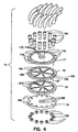
- twist-inserting apparatus 15 is shown in an exploded and an assembled view.
- twist-inserting apparatus 15 is formed from two identical disks 16 and 16'.
- a identical pattern cut into the disk 16 permits the disk 16 to be used for inserting both S-twist and Z-twist simply by inverting one disk 16 against the other.
- the location of the disks 16 relative to each other and the flow characteristics defined by the pattern establish the correct twist insertion.
- each of the disks 16, 16' includes various channels, nozzles and orifices which perform the yarn-twisting function.
- the disks 16, 16' are placed in overlying relation to each other and sandwiched between a top end block 17 and a bottom end block 18.
- the blocks 17 and 18 are held together by machine screws 19A which extend through holes in the disks 16, 16' and blocks holes 17A, 18A in respective blocks 17, 18.
- the screws are captured by respective nuts 19B, as shown.
- Top block 17 functions as an air feed manifold and distributes air from a remote supply of pressurized air to the twist-inserting apparatus 15 under the control of programmed solenoids.
- Air hoses connect the air supply to the disks 16, 16' through air inlet holes 17B.
- the yarns 11 pass through yarn orifices 17C and 18B in respective blocks 17 and 18.
- the twist-inserting apparatus 15 is a compact, simple device with no moving parts and which can be quickly and reliably modified as needed.
- Disk 16 is formed from relatively thin sheet stainless steel on the order of 3,2 mm (125 in.) thick.
- a six-ply yarn can be processed, and for this purpose six yarn orifices 16A are formed in the central area of the disk 16. See also Figure 5. Moving yarns pass through these orifices 16A perpendicular to the major plane of die disk 16.
- Six air channels 16B are formed in the disk 16 and extend radially-inwardly from six respective enlarged air supply holes 16C. These channels 16B communicate with the yarn orifices 16A by means of six respective nozzles 16D. This arrangement is best shown in Figures 9A and 9B. Note that the nozzle 16D intersects the orifice at a tangent, so that air traveling from the nozzle 16D into the orifice 16A creates a cyclonic air circulation pattern. This air movement contains sufficient energy to cause the moving yarn to be twisted about its own axis.
- the orifices 16A, air channels 16B connection, air supply holes 16C and nozzles 16D are cut into the disk 16 and communicate with both major surfaces of the disk 16.
- the disk 16 shown in Figure 7 is simply the inverted disk 16 shown in Figure 6. This has the effect of reversing the tangent angle at which the air from the nozzles 16 intersect the moving yarn.
- Disk 16 also has 12 screw holes 16E for receiving the screws 19, as shown in Figures 4 and 5.
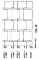
- disk 16 is provided with 6 air supply holes 16F which do not interconnect with the air channels 16B of the same disk 16, but with the air supply channels 16B of an inverted disk 16', as shown in Figure 4. This is accomplished merely by virtue of the fact that the disk 16' is inverted with respect to the other disk 16. This is illustrated in Figure 8, where disks 16 and 16' are shown in position.
- the top disk 16 is shown as if it were transparent.
- the yarn orifices 16A are exactly aligned with each other, so that each of the six yarn strands passes through one of the aligned yarn orifices 16A in both disks 16 and 16'.
- the six air supply holes 16C in disk 16 are connected through a manifold to an air solenoid and thus operate in unison.
- S-twist is being inserted in the yarns.
- Z-twist is being inserted in the yarns.
- control of the alternating twist directions produces a false-twisted yarn with the desired characteristics, with twist reversal spots between the areas of alternating twist, as shown in Figure 10.
- 12 air supply hoses interconnect into the 12 air supply holes of disks 16 and 16'. Due to the 30 degree axial offset of the disks 16 and 16' relative to each other, six of the air channels direct air to the nozzles 16D which will insert S-twist in the yarn and six of the air channels direct air to the nozzles 16D which will insert Z-twist in the yarn.
- the ratio of the area of the nozzle 16D to the yarn orifice is approximately 1:6.
- the preferred ratio of the width of the nozzle 16D to the width of the air channel 16B is 1:3.
- a typical process using the twist-inserting apparatus 15 according to the preferred embodiment of this invention is as follows: Yarn ends 6 Yarn count 1518 dtex (1380 den)/4ply Yarn type Nylon Yarn speed 366m/min (400 yds/min) false tpm 118 (3 tpi) air N/mm 2 551,6 (80 psi) dist. between twist reversals 1,2 m (48in)
- the top and bottom end blocks 17 and 18 may be made from the same stainless steel as are the disks 16, 16', or may be made from aluminum or other suitable metal.
- the thickness of the end blocks 17 and 18 is determined principally by the strength needed to prevent deformation of the disks 16, 16', provide mass sufficient to prevent vibration or oscillation during use, and to provide sufficient size for proper mounting. Note that the bottom end block has only screw holes 18A
- the plied yarn 11 is comprised of a "S"-twisted portion 11A, and an "Z"-twisted portion 11B separated by a twist reversal segment 11C constructed of entangled fibers in the manner described below.
- the spacing of these twist reversal segments 11C is a significant factor in the ultimate characteristics of the yarn.
- the twist in the yarns 11 is locked into the yarn in the alternate directions by the twist reversal segments 11C.
- a drive motor 30 is mounted on the machine frame (not shown).
- a protective shroud 31 is positioned on one side of the motor 30 and encloses several components of the rotary air-jet assembly 20.
- a manifold housing 32 is mounted in shroud 31 and carries an air manifold 33 which supplies pressurized air to the rotary air-jet assembly 20. Air is supplied to the manifold by an air inlet port 33A.
- a rotating, cylindrical air-jet carried for rotation on the motor shaft 35 of the drive motor 30.
- die air-jet nozzle 34 may be driven by a belt, gear transmission or other suitable power transmission device. Rotating nozzle 34 is provided with an air-jet orifice 37 through which air may pass at predetermined intervals.
- Shroud 31 is provided with a cut-away section 39 defined by the walls of shroud 31, into which is placed a yarn twister plate 40.
- Yarn guide plate 40 is provided with a vertically-oriented yarn slot 41 through which the plied yarns 11 pass after leaving the twist-inserting apparatus 15.
- a yarn slot orifice 42 in the yarn slot 41 communicates with the air-jet nozzle 34.
- the yarn guide plate 40 fits over the cut-away section 39 to guide the plied yarn 11 properly past the air jet nozzle 34.
- a cover 45 is positioned over the yarn slot 41 of the yarn guide plate 40 to prevent uncontrolled escape of air from the proximity of the yarn 11 and to produce in cooperation with the yarn guide plate 40 the air turbulence which entangles the yarn 11.
- the cover 45 has an upstream yarn entrance 45A and a downstream yarn exit 45B.
- An end cap 46 encloses the end of the shroud 31. Note that the air-jet nozzle 34 is the only moving part of the air-jet assembly 20 other than the shaft and associated elements of the motor 30.
- Air inlet port 33A feeds pressurized air into the manifold 33. Air is ejected from the manifold through an air outlet port 48.
- the forward walls of the manifold 33 defining the air outlet port 48 are arcuately-shaped to seal against the inside wall of rotating air-jet nozzle 34 to prevent air from escaping into the interior of the air-jet nozzle 34.
- the air-jet orifice 37 moves past the air outlet port 48.
- Each complete rotation thus creates a pulse of pressurized air which passes though the air outlet port 48, the air-jet orifice 37, the yarn slot orifice 42 and into the yarn slot 41 in the yarn guide plate 40.
- the distance between the air-jet nozzle 34 and the yarn guide plate 40 should be as short as possible in order to achieve a short, dense twist reversal segment 11C.
- two air-jet orifices 37A and 37B can be formed in the air-jet nozzle 34, thus permitting the formation of two twist reversal segments 11C for each rotation of the air-jet nozzle 34.
- Other arrangements are possible, and need not be symmetrical.
- twist reversal points which are at varying distances from each other can be created by selective placement of air-jet orifices 37 at different spacings around the circumference of the air-jet nozzle 34.
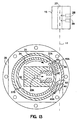
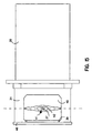
- Figures 14 and 15 illustrate the twist reversal formation position of the air-jet nozzle 34.
- the air-jet orifice 37 communicates for passage of pressurized air from the air-jet orifice 37 into the area of the yarn 11 by passing into the area of the yarn slot 41.
- the inside wall of the cover 45 acts as diffuser to create randomly swirling jets of high-pressure, high velocity blasts of air which pass in and through the yarn 11, tangling the yarn 11 at the point where the yarn 11 is exposed to the air blast and forming the twist reversal segments 11C.
- the air-jet nozzle 34 will entangle a given spot on the yarn 11 for each passage of the air-jet orifice 37 past the yarn slot 41.
- the length of the twist reversal segment 11C should be approximately no more than the length of the yarn slot orifice 42.
- the cover 45 is removed to show the position of the air-jet orifice 37. Note that in this view the air-jet orifice 37 is laterally centered with reference to the yarn slot orifice 42. In this position the air blast will create a generally symmetrical tangle of fibers in the yarn 11--neither favoring the Z-twist or S-twist direction.
- Figure 17 shows how the opposite occurs when the air-jet orifice 37 is moved laterally off center to the left.
- the proper arrangement for a short point of twist reversal is to use an air-jet nozzle 34 with two air-jet orifices 37A and 37B ( Figure 13) where one air-jet orifice 37A or 37B is laterally offset to the right of the yarn slot orifice 42 to entangle the plied yarn 11 when the twist changes from "Z" to "S”; and use the other of the air-jet orifices 37A or 37B, which is offset to the inside of the yarn slot orifice 42, to entangle the plied yarn 11 when the twist changes from "S" to "Z".
- the table illustrates that the active air-blast time of the rotary air-jet assembly 20 is used to time the "on” and "off" time of the twist-inserting apparatus 15 for a air-jet nozzle 34 with a single air-jet orifice 37.
- the air for the S-twist air supply holes 16C of the twist-inserting apparatus 15 is turned on before the air for the Z-twist air supply holes 16F is turned off. This is accomplished through electronic timing.
- the same type of timing is also used for the alternating air supply which inserts the S-twist and Z-twist at the twist-inserting apparatus 15.
- This overlapping timing can be used if desired to achieve a short as possible twist reversal segment 11C in the plied yarn 11 since there is some unavoidable delay in the time from when the solenoid is switched on until the air is fully active in the twist-inserting apparatus 15.
- Figure 19 shows the timing for a rotary air-jet assembly 20 with an air-jet nozzle 34 having the two circumferentially-offset air-jet orifices 37A and 37B ( Figure 13) where the two air-jet orifices 37A and 37B are laterally offset to each other and are laterally displaced from the center of the yarn slot orifice 42 to accomplish a short twist reversal segment 11C.
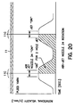
- the timing diagram in Figure 20 shows how the rotational speed of the rotary air-jet assembly 20 is controlled.
- An electronic drive (not shown) for the rotary air-jet assembly 20 is programmed in such a manner that the air-jet orifice 37 reaches the velocity of the traveling plied yarn 11 during the time that entangling of the yarn 11 is taking place.
- the rotational speed of the air-jet nozzle 34 with its air-jet orifice 37 is slowed down between each splicing cycle in order to wait for the next twist-reversal, at which time it has been brought up speed to match the velocity of the plied yarn 11.
- the desired yarn-length between the twist reversal segments 11C and the processing speed of the yarn 11 dictates the velocity profile of the rotary air-jet assembly 20.
- the relationship of the rotary air-jet assembly 20 in relation to the plied yarn 11 is given in Figure 20.
- the rotational velocity of the air-jet nozzle 34 is timed in two basic ways:
- the air blast from the air-jet orifice 37 is timed to coincide with the passing of the point where the twist reversal segment 11C of the yarn 11 is to be formed.
- the rotational speed of the air jet nozzle 34 matches the velocity of the traveling yarn 11 in order that the air blast is, relatively speaking, stationary with the point of creation of the twist reversal segment 11C during the entangling process.
- the shaded area shown below the rotational velocity line in Figure 20 is the integral of the rotational velocity and the process time and is equal to the angular distance between two air-jet orifices 37A and 37B of the rotary air-jet assembly 20 shown in Figure 13.
- the electronic controller for the drive motor 30 of the rotary air-jet assembly 20 is not shown, but may be a known angular encoder on the drive motor 30. It is naturally understood that the distance between the twist reversal segments 11C can be changed through the electronic controller, which will automatically adjust the speed of the drive motor 30 and hence of the air-jet nozzle 34 to match the requirements of the system to cause tangling of the yarn 11 at the desired points of twist reversal, and matching of the velocity of the air-net nozzle 34 with the velocity of the traveling yarn 11.
- the electronic control of the rotary air-jet assembly 20 may be by an encoder on the drive of the take-up winder 25 ( Figure 1), which is then used as the master input for the electronic control, and from which the location of the point of twist reversal and the point where the yarn 11 is entangled is determined.
- a fluid-jet false-twisting apparatus according to another embodiment of the invention is shown and generally indicated at broad reference numeral 100.
- multi-filament yarns 101 are taken from respective supply packages 102 and passed through a yarn separator 104, four twist-inserting air-jets, referred to as "twist-inserting apparatus 105" (one for each yarn 101) and a rotary air jet assembly 120, where the yarns 101 are plied by the combined action of the twist-inserting apparatus 105 and the rotary air jet assembly 120 in the manner described above in relation to Figures 1-20.
- Air is supplied to the twist-inserting apparatus 105 from a source of pressurized air by means of solenoid valves controlled by mechanical, electromechanical or, preferably, electronic means (not shown).
- the yarns 101 are guided around overfeed drive rolls 122, 123 where the tension on the plied yarns 101 is reduced to a predetermined extent before delivery to a yarn accumulator 130 and to a downstream take-up winder 140.
- the yarn accumulator may be a Belmont Model AC-50 accumulator, and the winder may be a Model AD-25 take-up winder.
- the yarn accumulator 130 helps buffer variations in yarn tension, and permits the system to continue operating during package changes. In addition, any lengths of defective yarn can easily be seen in the accumulator and removed during machine operation.
- the accumulator 130 may act as the "master encoder" for purposes of determining actuation of the various twist inserting and entangling functions described above.
- the overfeed drive rolls 122, 123 may be removed and replace with a nip roll (not shown), in which case the nip rolls may be used as the constant speed master off of which the other functions of the fluid-jet false-twisting apparatus 100 are timed.
Landscapes
- Engineering & Computer Science (AREA)
- Mechanical Engineering (AREA)
- Textile Engineering (AREA)
- Yarns And Mechanical Finishing Of Yarns Or Ropes (AREA)
Claims (17)
- Vorrichtung zum Einleiten eines Dralls in einem laufenden Faden, welche folgendes aufweist:(a) einen ersten Körper (16) mit(i) einer durch ihn hindurchführenden Öffnung (16A) zur Ermöglichung des Durchganges eines laufenden Garns (11),(ii) einem durch ihn hindurchführenden und mit der genannten Öffnung (16A) in Verbindung stehenden Luftkanal (16B), wobei(iii) der genannte Kanal (16B) mit der genannten Öffnung (16A) in einem zur Bewegungsbahn des Garns (11) durch die Öffnung (16A) tangential versetzten Winkel in Verbindung steht, um ein zyklonartiges Luftströmungsmuster in der Öffnung (16A) zu erzeugen, um während des Durchganges des Garns (11) durch die Öffnung (16A) einen Drall mit vorherbestimmter Richtung in das Garn (11) einzuleiten, dadurch gekennzeichnet, dass(b) der genannte erste Körper (16) dazu ausgebildet ist, relativ zu einem zweiten, gleichen Körper (16') verdreht zu werden und mit dem zweiten, gleichen Körper (16') aufeinanderliegend eingestellt zu werden, wobei der Luftkanal (16B) des ersten Körpers (16) eine vorbestimmte Drallrichtung in das Garn (11) einleitet und der Luftkanal (16B) des zweiten Körpers (16') eine andere vorbestimmte Drallrichtung in das Garn (11) einleitet.
- Vorrichtung zum Einleiten eines Dralls in einen laufenden Faden gemäß Anspruch 1, bei der(a) der genannte erste Körper (16) scheibenförmig ist,(b) die Öffnung (16A) axial durch den genannten Körper (16) hindurchführt und(c) zumindest ein Bereich des genannten Luftkanals (16B) radial durch den genannten Körper (16) hindurchführt.
- Vorrichtung zum Einleiten eines Dralls in einen laufenden Faden gemäß Anspruch 2, bei der der genannte erste Körper (16) folgendes einschließt:(a) Eine Vielzahl von beabstandeten Öffnungen (16A) und(b) eine Vielzahl von Luftkanälen (16B), wobei einer der Luftkanäle (16B) der Vielzahl mit einer entsprechenden Öffnung der genannten Öffnungen (16A) in Verbindung steht.
- Vorrichtung zum Einleiten eines Dralls in einen laufenden Faden gemäß Anspruch 3, bei der(a) die Öffnungen (16A) in einem mittleren Bereich des Körpers (16) zusammengefasst sind und(b) die Luftkanäle (16B) sich von einem Randbereich des Körpers (16) radial nach innen zu den genannten Öffnungen (16A) hin erstrecken.
- Vorrichtung zum Einleiten eines Dralls in einen laufenden Faden gemäß Anspruch 4, die(a) zumindest vier symmetrisch beabstandete Öffnungen (16A) aufweist, welche in dem genannten Körper (16) ausgebildet sind und bei der(b) zumindest vier Luftkanäle (16B) sich von einem Randbereich des genannten Körpers (16) radial nach innen erstrecken, bis sie in Verbindung mit den jeweiligen Öffnungen (16A) kommen.
- Vorrichtung zum Einleiten eines Dralls in einen laufenden Faden gemäß Anspruch 5, bei der jeder der Luftkanäle (16B) die jeweilige Öffnung (16A) in Bezug auf die Richtung des laufenden Garns im rechten Winkel schneidet.
- Vorrichtung zum Einleiten eines Dralls in einen laufenden Faden gemäß Anspruch 1, welche(e) Auswahlmittel zum Auswählen der einen oder anderen Luftkanäle (16B) des ersten Körpers (16) oder zweiten Körpers (16'), um der jeweiligen ersten oder zweiten Öffnung (16A) Luft zuzuführen und dadurch eine vorherbestimmte Drallrichtung in das Garn (11) einzuleiten.
- Vorrichtung zum Einleiten eines Dralls in einen laufenden Faden gemäß Anspruch 7, bei der der genannte erste Körper (16) eine kreisförmige Scheibe aufweist, welche gegenüberliegende erste und zweite Hauptflächen hat, und bei der die Vorrichtung weiterhin(a) einen oberen Endblock (17) und einen unteren Endblock (18) hat, zwischen denen die genannten ersten und zweiten Scheiben sandwichartig angeordnet sind und(b) Luftzuführanschlüssen (17B) aufweist, die durch den genannten oberen Endblock (17) hindurchführen und mit den jeweiligen Luftkanälen (16B) in den ersten und zweiten Scheiben in Verbindung stehen.
- Vorrichtung zum Einleiten eines Dralls in einen laufenden Faden gemäß Anspruch 8, bei der die genannten Luftkanäle (16B) sich durch die Dicke des Körpers (16, 16') erstrecken und mit den gegenüberliegenden ersten und zweiten Hauptflächen Verbindung haben.
- Vorrichtung zum Einleiten eines Dralls in einen laufenden Faden gemäß Anspruch 1, bei der der genannte Luftkanal (16B) mit der genannten Öffnung (16A) über eine jeweilige Luftkanaldüse (16D) in Verbindung steht und bei der die Fläche, welche durch die Öffnung der Düse (16D) in die Öffnung (16A) definiert wird, nicht mehr als ein Viertel der Fläche der Öffnung (16A) beträgt.
- Vorrichtung zum Einleiten eines Dralls in einen laufenden Faden gemäß Anspruch 1, bei der der genannte Luftkanal (16B) mit der genannten Öffnung (16A) über eine jeweilige Luftkanaldüse (16D) in Verbindung steht und bei der die Fläche, welche durch die Öffnung der Düse (16D) in die Öffnung (16A) definiert wird, etwa ein Sechstel der Fläche der Öffnung (16A) beträgt.
- Vorrichtung zum Einleiten eines Dralls in einen laufenden Faden gemäß Anspruch 1, bei der der genannte Luftkanal (16B) mit der genannten Öffnung (16A) über eine jeweilige Luftkanaldüse (16D) in Verbindung steht und bei der die Breite der Düse (16D) nicht mehr als die Hälfte der Breite des Luftkanals (16B) beträgt.
- Vorrichtung zum Einleiten eines Dralls in einen laufenden Faden gemäß Anspruch 1, bei der der genannte Luftkanal (16B) mit der genannten Öffnung (16A) über eine jeweilige Luftkanaldüse (16D) in Verbindung steht und bei der die Breite der Düse (16D) nicht mehr als ein Drittel der Breite des Luftkanals (16B) beträgt.
- Vorrichtung zum Einleiten eines Dralls in einen laufenden Faden gemäß Anspruch 1, welche obere und untere Endblöcke (17, 18) aufweist, die die genannten ersten und zweiten Körper (16, 16') umfassen, wobei der genannte obere Endblock (17) Luftzuführanschlüsse (17B) aufweist, die sich durch ihn hindurch erstrecken und mit jeweiligen Luftkanälen (16B) in den ersten und zweiten Scheiben (16, 16') in Verbindung stehen, um dort Druckluft zuzuführen.
- Vorrichtung nach Anspruch 14, bei der der genannte erste Körper (16) und der genannte zweite Körper (16') jeweils eine erste und eine zweite Scheibe aufweisen.
- Vorrichtung nach Anspruch 15, bei der die genannten ersten und zweiten Scheiben (16, 16') jeweils eine festgelegte Dicke aufweisen, welche eine Abmessung eines Luftkanals festlegen.
- Vorrichtung nach Anspruch 16, bei der die genannte Vorrichtung (15) dazu ausgebildet ist, erste und zweite Scheiben (16, 16') aufzunehmen, welche unterschiedliche, festgelegte Dicken aufweisen, damit sie einen Luftkanal (16B) aufnehmen können, der ein größeres oder kleineres Luftfördervermögen hat, wobei erste und/oder zweite Scheiben (16, 16') in der genannten Vorrichtung (15) auswechselbar sind, um das Luftfördervermögen zu vergrößern oder zu verkleinern, welches für eine gegebene Garngröße, die Ausbildung oder das Ausmaß der Dralleinleitung erforderlich ist.
Applications Claiming Priority (2)
| Application Number | Priority Date | Filing Date | Title |
|---|---|---|---|
| US103947 | 1993-08-10 | ||
| US09/103,947 US6052983A (en) | 1998-06-24 | 1998-06-24 | Fluid-jet twist-inserting apparatus and method |
Publications (2)
| Publication Number | Publication Date |
|---|---|
| EP0979890A1 EP0979890A1 (de) | 2000-02-16 |
| EP0979890B1 true EP0979890B1 (de) | 2003-04-09 |
Family
ID=22297851
Family Applications (1)
| Application Number | Title | Priority Date | Filing Date |
|---|---|---|---|
| EP99304942A Expired - Lifetime EP0979890B1 (de) | 1998-06-24 | 1999-06-23 | Fluidum-Strahl Zwirnvorrichtung und Verfahren |
Country Status (3)
| Country | Link |
|---|---|
| US (2) | US6052983A (de) |
| EP (1) | EP0979890B1 (de) |
| DE (1) | DE69906644T2 (de) |
Families Citing this family (15)
| Publication number | Priority date | Publication date | Assignee | Title |
|---|---|---|---|---|
| US6052983A (en) * | 1998-06-24 | 2000-04-25 | Belmont Textile Machinery Co., Inc. | Fluid-jet twist-inserting apparatus and method |
| DE10003216C1 (de) * | 2000-01-26 | 2001-09-06 | Heberlein Fasertech Ag | Luftdralldüse |
| US6957770B1 (en) * | 2002-05-10 | 2005-10-25 | Biopay, Llc | System and method for biometric authorization for check cashing |
| US7753268B1 (en) | 2002-05-10 | 2010-07-13 | Phoenix Check Cashing, Inc. | System and method for negotiable instrument cashing transaction assistance procedures |
| US7520422B1 (en) | 2002-05-10 | 2009-04-21 | Phoenix Check Cashing, Inc. | System and method for depositing negotiable instruments |
| US7299615B2 (en) * | 2004-06-18 | 2007-11-27 | Mannington Mills, Inc. | Variable twist level yarn using fluid twisting |
| US7480969B2 (en) * | 2004-09-10 | 2009-01-27 | Rhyne Jeffrey T | Apparatus and method for conditioning air-entangled yarn |
| US7406818B2 (en) * | 2004-11-10 | 2008-08-05 | Columbia Insurance Company | Yarn manufacturing apparatus and method |
| US20100258344A1 (en) * | 2005-02-09 | 2010-10-14 | Laird Technologies, Inc. | Flame retardant emi shields |
| US20110016841A1 (en) * | 2007-05-18 | 2011-01-27 | Drexel University | Alternate twist ply yarn with low residual twist |
| CA2732718C (en) * | 2008-07-30 | 2014-10-28 | Invista Technologies S.A.R.L. | Systems and methods of twisting and heat-setting yarn, and apparatus for twisting yarn and heat-setting yarn |
| US9850606B2 (en) * | 2015-03-27 | 2017-12-26 | Goodrich Corporation | System and method for multiple surface air jet needling |
| WO2016164777A1 (en) * | 2015-04-08 | 2016-10-13 | Shaw Industries Group, Inc. | Yarn texturizing apparatus and method |
| US10017887B2 (en) * | 2016-03-22 | 2018-07-10 | Goodrich Corporation | System and method for multiple surface water jet needling |
| US10081892B2 (en) | 2016-08-23 | 2018-09-25 | Goodrich Corporation | Systems and methods for air entanglement |
Family Cites Families (9)
| Publication number | Priority date | Publication date | Assignee | Title |
|---|---|---|---|---|
| BE758698A (fr) * | 1969-11-10 | 1971-05-10 | Uniroyal Inc | Appareil de texturisation d'un fil synthetique |
| US3775955A (en) * | 1971-07-30 | 1973-12-04 | Bigelow Sanford Inc | Composite false-twist yarns, methods and apparatus |
| SU562595A1 (ru) * | 1975-07-29 | 1977-06-25 | Всесоюзный Научно-Исследовательский Институт Легкого И Текстильного Машиностроения | Устройство дл получени самокрученой пр жи |
| US4058960A (en) * | 1976-08-17 | 1977-11-22 | Pavel Mikhailovich Movshovich | Distributing device for supplying compressed air to chambers of apparatus for making self-twisted product |
| GB1592646A (en) * | 1976-12-01 | 1981-07-08 | Ici Ltd | Yarn treatment |
| US5228282A (en) * | 1988-04-15 | 1993-07-20 | E. I. Du Pont De Nemours And Company | Apparatus for forming alternate twist plied yarn |
| US5619848A (en) * | 1995-08-09 | 1997-04-15 | Prospin Industries, Inc. | Method and apparatus for automatically removing an imperfection from spun filament yarn and staple fibers |
| US6089009A (en) * | 1997-08-28 | 2000-07-18 | Belmont Textile Machinery Co., Inc. | Fluid-jet false-twisting method and product |
| US6052983A (en) * | 1998-06-24 | 2000-04-25 | Belmont Textile Machinery Co., Inc. | Fluid-jet twist-inserting apparatus and method |
-
1998
- 1998-06-24 US US09/103,947 patent/US6052983A/en not_active Expired - Lifetime
-
1999
- 1999-06-23 EP EP99304942A patent/EP0979890B1/de not_active Expired - Lifetime
- 1999-06-23 DE DE69906644T patent/DE69906644T2/de not_active Expired - Fee Related
-
2000
- 2000-04-14 US US09/549,747 patent/US6345491B1/en not_active Expired - Lifetime
Also Published As
| Publication number | Publication date |
|---|---|
| US6345491B1 (en) | 2002-02-12 |
| EP0979890A1 (de) | 2000-02-16 |
| DE69906644T2 (de) | 2004-02-26 |
| DE69906644D1 (de) | 2003-05-15 |
| US6052983A (en) | 2000-04-25 |
Similar Documents
| Publication | Publication Date | Title |
|---|---|---|
| EP0979890B1 (de) | Fluidum-Strahl Zwirnvorrichtung und Verfahren | |
| US3775955A (en) | Composite false-twist yarns, methods and apparatus | |
| US6119320A (en) | Method and apparatus for producing a multicolored yarn from differently colored part-threads of endless filament | |
| EP0899366B1 (de) | Fluidum-Strahl Falschzwirnvorrichtung, Verfahren und Produkt | |
| US4251904A (en) | Yarn treating apparatus | |
| US3364537A (en) | Apparatus for interlacing multifilament yarn | |
| US5008992A (en) | Method of producing a bulked composite yarn | |
| US3005251A (en) | Yarn fluid treatment process and apparatus | |
| US6041587A (en) | Machine for making a mixed yarn by combining two false-twist textured yarns | |
| JP5039546B2 (ja) | フィラメント糸及び星糸、マイグレーション加工糸、仮撚り糸を処理するための装置及び方法 | |
| US5713113A (en) | Device for treating at least one running multifilament yarn | |
| US4083172A (en) | Control system for pneumatically treated yarns | |
| US4934134A (en) | Apparatus for randomizing multiple yarn strands | |
| US5054173A (en) | Method and apparatus for the enhanced crimping of multifilament yarn | |
| US11970794B2 (en) | Yarn treatment device and method | |
| EP3280835B1 (de) | Vorrichtung und verfahren zur garntexturierung | |
| US7288306B2 (en) | Textile substrate having low variable twist yarn | |
| KR20070064623A (ko) | 방적사의 공기 인터레이싱을 위한 고성능 장치 및 방법 | |
| US3742692A (en) | Apparatus and method for false twisting yarn | |
| EP0811711A2 (de) | Verfahren zur Behandlung eines Garnes und Vorrichtung | |
| US7299615B2 (en) | Variable twist level yarn using fluid twisting | |
| US3097412A (en) | Yarn treating apparatus | |
| US4899426A (en) | Method and apparatus for randomizing multiple yarn strands | |
| US4422224A (en) | Apparatus for interlacing multifilament yarn | |
| TWI823930B (zh) | 用於在紗線上產生可變拉伸效果的裝置及用於製造花式紗線的機器及方法 |
Legal Events
| Date | Code | Title | Description |
|---|---|---|---|
| PUAI | Public reference made under article 153(3) epc to a published international application that has entered the european phase |
Free format text: ORIGINAL CODE: 0009012 |
|
| AK | Designated contracting states |
Kind code of ref document: A1 Designated state(s): BE CH DE FR GB IT LI |
|
| AX | Request for extension of the european patent |
Free format text: AL;LT;LV;MK;RO;SI |
|
| 17P | Request for examination filed |
Effective date: 20000228 |
|
| AKX | Designation fees paid |
Free format text: BE CH DE FR GB IT LI |
|
| GRAH | Despatch of communication of intention to grant a patent |
Free format text: ORIGINAL CODE: EPIDOS IGRA |
|
| GRAH | Despatch of communication of intention to grant a patent |
Free format text: ORIGINAL CODE: EPIDOS IGRA |
|
| GRAA | (expected) grant |
Free format text: ORIGINAL CODE: 0009210 |
|
| AK | Designated contracting states |
Designated state(s): BE CH DE FR GB IT LI |
|
| REG | Reference to a national code |
Ref country code: GB Ref legal event code: FG4D |
|
| REG | Reference to a national code |
Ref country code: CH Ref legal event code: EP |
|
| REG | Reference to a national code |
Ref country code: CH Ref legal event code: NV Representative=s name: INTERPAT LAW AG |
|
| PGFP | Annual fee paid to national office [announced via postgrant information from national office to epo] |
Ref country code: DE Payment date: 20030825 Year of fee payment: 5 |
|
| PGFP | Annual fee paid to national office [announced via postgrant information from national office to epo] |
Ref country code: GB Payment date: 20031223 Year of fee payment: 5 |
|
| PGFP | Annual fee paid to national office [announced via postgrant information from national office to epo] |
Ref country code: FR Payment date: 20031226 Year of fee payment: 5 |
|
| PGFP | Annual fee paid to national office [announced via postgrant information from national office to epo] |
Ref country code: CH Payment date: 20031229 Year of fee payment: 5 |
|
| ET | Fr: translation filed | ||
| PGFP | Annual fee paid to national office [announced via postgrant information from national office to epo] |
Ref country code: BE Payment date: 20040128 Year of fee payment: 5 |
|
| PLBE | No opposition filed within time limit |
Free format text: ORIGINAL CODE: 0009261 |
|
| STAA | Information on the status of an ep patent application or granted ep patent |
Free format text: STATUS: NO OPPOSITION FILED WITHIN TIME LIMIT |
|
| 26N | No opposition filed |
Effective date: 20040112 |
|
| PG25 | Lapsed in a contracting state [announced via postgrant information from national office to epo] |
Ref country code: GB Free format text: LAPSE BECAUSE OF NON-PAYMENT OF DUE FEES Effective date: 20040623 |
|
| PG25 | Lapsed in a contracting state [announced via postgrant information from national office to epo] |
Ref country code: LI Free format text: LAPSE BECAUSE OF NON-PAYMENT OF DUE FEES Effective date: 20040630 Ref country code: CH Free format text: LAPSE BECAUSE OF NON-PAYMENT OF DUE FEES Effective date: 20040630 Ref country code: BE Free format text: LAPSE BECAUSE OF NON-PAYMENT OF DUE FEES Effective date: 20040630 |
|
| BERE | Be: lapsed |
Owner name: *BELMONT TEXTILE MACHINERY CO. INC. Effective date: 20040630 |
|
| PG25 | Lapsed in a contracting state [announced via postgrant information from national office to epo] |
Ref country code: DE Free format text: LAPSE BECAUSE OF NON-PAYMENT OF DUE FEES Effective date: 20050101 |
|
| GBPC | Gb: european patent ceased through non-payment of renewal fee |
Effective date: 20040623 |
|
| REG | Reference to a national code |
Ref country code: CH Ref legal event code: PL |
|
| PG25 | Lapsed in a contracting state [announced via postgrant information from national office to epo] |
Ref country code: FR Free format text: LAPSE BECAUSE OF NON-PAYMENT OF DUE FEES Effective date: 20050228 |
|
| REG | Reference to a national code |
Ref country code: FR Ref legal event code: ST |
|
| PG25 | Lapsed in a contracting state [announced via postgrant information from national office to epo] |
Ref country code: IT Free format text: LAPSE BECAUSE OF NON-PAYMENT OF DUE FEES Effective date: 20050623 |