EP0979777B1 - Label system and method for label alignment and placement - Google Patents
Label system and method for label alignment and placement Download PDFInfo
- Publication number
- EP0979777B1 EP0979777B1 EP99115816A EP99115816A EP0979777B1 EP 0979777 B1 EP0979777 B1 EP 0979777B1 EP 99115816 A EP99115816 A EP 99115816A EP 99115816 A EP99115816 A EP 99115816A EP 0979777 B1 EP0979777 B1 EP 0979777B1
- Authority
- EP
- European Patent Office
- Prior art keywords
- label
- alignment
- container
- symbology
- bar code
- Prior art date
- Legal status (The legal status is an assumption and is not a legal conclusion. Google has not performed a legal analysis and makes no representation as to the accuracy of the status listed.)
- Expired - Lifetime
Links
- 238000000034 method Methods 0.000 title claims description 13
- 238000005070 sampling Methods 0.000 description 9
- 238000012360 testing method Methods 0.000 description 4
- 238000004458 analytical method Methods 0.000 description 3
- 229910003460 diamond Inorganic materials 0.000 description 3
- 239000010432 diamond Substances 0.000 description 3
- 239000003086 colorant Substances 0.000 description 2
- 238000012790 confirmation Methods 0.000 description 2
- 238000012863 analytical testing Methods 0.000 description 1
- 239000008280 blood Substances 0.000 description 1
- 210000004369 blood Anatomy 0.000 description 1
- 239000003153 chemical reaction reagent Substances 0.000 description 1
- 238000010586 diagram Methods 0.000 description 1
- 239000000203 mixture Substances 0.000 description 1
Images


Classifications
-
- B—PERFORMING OPERATIONS; TRANSPORTING
- B65—CONVEYING; PACKING; STORING; HANDLING THIN OR FILAMENTARY MATERIAL
- B65C—LABELLING OR TAGGING MACHINES, APPARATUS, OR PROCESSES
- B65C9/00—Details of labelling machines or apparatus
- B65C9/40—Controls; Safety devices
- B65C9/42—Label feed control
- B65C9/44—Label feed control by special means responsive to marks on labels or articles
-
- B—PERFORMING OPERATIONS; TRANSPORTING
- B65—CONVEYING; PACKING; STORING; HANDLING THIN OR FILAMENTARY MATERIAL
- B65C—LABELLING OR TAGGING MACHINES, APPARATUS, OR PROCESSES
- B65C9/00—Details of labelling machines or apparatus
- B65C9/46—Applying date marks, code marks, or the like, to the label during labelling
-
- Y—GENERAL TAGGING OF NEW TECHNOLOGICAL DEVELOPMENTS; GENERAL TAGGING OF CROSS-SECTIONAL TECHNOLOGIES SPANNING OVER SEVERAL SECTIONS OF THE IPC; TECHNICAL SUBJECTS COVERED BY FORMER USPC CROSS-REFERENCE ART COLLECTIONS [XRACs] AND DIGESTS
- Y10—TECHNICAL SUBJECTS COVERED BY FORMER USPC
- Y10T—TECHNICAL SUBJECTS COVERED BY FORMER US CLASSIFICATION
- Y10T156/00—Adhesive bonding and miscellaneous chemical manufacture
- Y10T156/10—Methods of surface bonding and/or assembly therefor
- Y10T156/1002—Methods of surface bonding and/or assembly therefor with permanent bending or reshaping or surface deformation of self sustaining lamina
- Y10T156/1028—Methods of surface bonding and/or assembly therefor with permanent bending or reshaping or surface deformation of self sustaining lamina by bending, drawing or stretch forming sheet to assume shape of configured lamina while in contact therewith
- Y10T156/1033—Flexible sheet to cylinder lamina
Definitions
- the present invention relates to a label system and method for proper positioning of a label on a container and for ensuring proper alignment of printed information on a label for subsequent reading.
- Proper placement of a printed label on a container is important for ensuring subsequent reading of the information printed on the label. If not properly placed, the printed information is not easily seen, or cannot easily be scanned, by automated equipment.
- Proper placement of the bar code information on a specimen collection container is important to ensure proper scanning of the encoded information by various clinical equipment and analytical testing instrumentation. If the bar code information is not properly positioned on the sample container, the scanner of the instrumentation may not be able to read the bar code, thus requiring the operator to manually scan the bar code information, or manually enter the bar code information into the instrumentation.
- Prior art document EP-A-0 441 365 upon which the preamble of independent claims 1 and 2 is based discloses a method and device for placing two labels on one object.
- the second label is positioned on the object with the help of the first label which is being detected by a sensor.
- the present invention is a label system according to claim 2 and method according to claim 1 for proper alignment and placement of a label on a container.
- the label system comprises a first label and a second label.
- the first label is located on a container and includes alignment symbology.
- the alignment symbology may be in the form of a distinct shape, such as a triangle or a diamond or in the form of a protrusion.
- the second label includes an alignment area corresponding to the alignment symbology of the first label.
- the alignment area may be in the form of an opening or a transparent portion.
- the second label is positioned on the container such that the alignment area of the second label is aligned with the alignment symbology of the first label, whereby the alignment symbology is detectable through the alignment area of the second label to assure proper alignment of the second label on the container.
- the first label may include alignment symbology in the form of a protrusion whereby the protrusion provides a means for detecting proper alignment both visually and through touch.
- the method of the present invention for placing a label on a container comprises the steps according to claim 1.
- An important attribute of the present invention is that proper placement of identification indicia on a label, for example, the bar code, ensures proper reading and scanning of the information by the scanners of the various instrumentation.
- the present invention provides, standardized positioning of identification indicia such as a bar code to insure efficiency and quality in analysis.
- a further attribute of the present invention is that an identification indicia is placed on a container, regardless of the size and shape of the container, so that the scanner of the instrumentation may be able to read the bar code and eliminate manually scanning the bar code information, or manually enter the bar code information into the instrumentation.
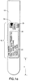
- FIG. 1a illustrates a container 10 with an alignment symbology 30 on an outer surface of container 10 .
- Alignment symbology 30 is designed to aid in the alignment of an identification label subsequently placed over the container.
- the alignment symbology may be any type of symbol capable of assisting in the proper positioning and alignment of a subsequently placed label.
- the alignment symbology may be a distinct shape in the form of a graphic or pictorial representation, such as a triangle, rectangle, diamond, circle, or the like, and mixtures thereof.
- the alignment symbology may be a protrusion which can be felt with the finger.
- container 10 includes a first label 20 affixed to the outer surface of the container or label bearing area 15 , with alignment symbology 30 printed on label 20 .
- Label 20 may further contain additional encoded or printed information thereon. Such as a bar code 25 and/or an alphanumeric indicia 23 , either or both of which may include information identifying the specific type of the container, the manufacturer lot number, the size and/or shape of the container and the reagents included within the container.
- an identification label 40 is provided for placement on container 10 .
- Identification label 40 may include encoded or printed information thereon, such as a bar code 45 and/or an alphanumeric indicia 43 , either or both or which may represent an identification of the sample contained within the container, information identifying the patient, what analyses are to be conducted on the sample and sampling information such as date and time of sampling.
- Identification label 40 is provided as a second label capable of being affixed over label 20 .
- Identification label 40 includes an alignment area 50 corresponding to alignment symbology 30 of label 20 .
- Alignment area 50 may be an opening or notched cut-away of label 40 .
- alignment symbology 30 is in the form of a v-shaped triangle and alignment area 50 is a v-shaped notch appearing on the edge of label 40 .
- alignment area 50 may be a transparent portion having a shape designed to fit over alignment symbology 30 , such as transparent portion 51 as shown in FIG. 2d.
- identification label 40 is positioned on container 10 such that alignment area 50 of identification label 40 is aligned with alignment symbology 30 of label 20 , with alignment symbology 30 being detectable through alignment area 50 , thereby assuring proper alignment of the identification label on container 10 .
- alignment symbology 30 and identification label 40 are contrasting colors, for example, alignment symbology 30 is printed in black ink as a geometric shape, and identification label 40 is a white label including alignment area 50 therethrough. Therefore, the sharp contrast between the colors of the alignment symbology 30 and alignment area 50 provides accurate assurance that identification label 40 is properly aligned over container 10 .
- alignment symbology 30 includes a protrusion, such as a v-shaped bump and alignment area 50 of identification label 40 is in the form of a v-shaped notch extending through identification label 40 . Therefore, the v-shaped notch is aligned with the v-shaped bump of container 10 or container label 20 when identification label 40 is positioned over container label 20 , with the v-shape ensuring both vertical and horizontal alignment of identification label 40 on container label 20 . Moreover, such a protrusion provides a means for detecting proper alignment both visually and through touch to assure proper placement of identification label 40 over container label 20 .
- container label 20 may include a plurality of alignment. Areas 50a and 50b at opposed label edges 41 and 42 . Alignment areas 50a and 50b are designed to cooperate with two separate alignment symbologies appearing on container 10 and/or container label 20 .
- alignment symbology 30 can be any shape or form, so long as alignment area 50 of identification label 40 properly corresponds to the shape and/or form of alignment symbology 30 .
- alignment area 50 can be in the shape of a diamond, or a circle which shapes would correspond to a similar shape alignment symbology appearing on container label 20 .
- alignment symbology 30 and alignment area 50 corresponding to shapes which are non-rotationally symmetrical, such as a polygon, to assure proper alignment in both a vertical and horizontal direction and prevent identification label 40 from being improperly skewed or canted.
- FIG. 3 The system and method for positionally locating indicia on a label for aligned placement of the indicia at a predetermined position on a container which is not in accordance with the invention is illustrated in FIG. 3.
- an operator such as a phlebotomist is provided with a portable sampling kit including a scanner, a microprocessor and a printer including a supply of labels for printing thereon.
- container 10 in the form of a blood collection tube is provided including bar code 25 including encoded information which identifies the container type and defines the location of label bearing area 15 unique to that container type.
- the phlebotomist is provided with a listing of patients requiring sampling. Each patient is provided with a patient identification bracelet, preferably including a bar code identification, as is well known in the art. The phlebotomist scans the identification information of the patient's bracelet with the scanner provided on the portable sampling kit.
- the microprocessor may provide confirmation to the phlebotomist that the patient requires specific testing.
- the phlebotomist selects the appropriate container 10 for containing the sample requiring testing.
- the phlebotomist scans bar code 35 on container 10 with the scanner.
- the portable sampling kit may provide the phlebotomist with confirmation that container 10 is appropriate for containing the sample requiring testing.
- Bar code 35 includes encoded information which identifies the container type and defines the location of label bearing area 15 unique to that container type. For example, as depicted in FIG 1a, container label is positioned at label bearing area 15 of container 10 at a predetermined distance h from the bottom of container 10 . This predetermined distance h is determined according to the container type including the size and shape of container 10 .
- the microprocessor of the sampling kit processes the encoded information of bar code 35 identifying the container type with respect to the location of label bearing area 15 .
- the microprocessor further identifies what information is required for printing on identification label 40 to be affixed to container 10 .
- Identification label 40 is provided with information identifying the patient, the type of sample, and what analyses are to be conducted on the sample, as well as sampling information such as date and time of sampling.
- Such information may be encoded as bar code 45 , or may be in alphanumeric form, such as alphanumeric indicia 43 or may be provided in both bar code 45 and alphanumeric indicia 43 .
- the microprocessor After identifying the container type and the information to be provided on the label, the microprocessor processes this information to determine the exact location for printing on identification label 40 .
- the microprocessor may be preprogrammed to ensure printing of bar code information at a specific predetermined position on a container, regardless of the size and shape of the container, so as to provide a standard position for such bar code information for all containers to effectuate subsequent reading, for example, by an automated analytical instrument including a bar code scanner.
- the microprocessor processes the information previously scanned from container label 20 with respect to the size of identification label 40 .
- the microprocessor determines the exact location for printing of the identification information on identification label 40 with respect to the predetermined standard position.
- the microprocessor processes the scanned information to determine that label bearing area 15 of container 10 is positioned distance h from the bottom of container 10 . Further, the microprocessorrecognizes from its memory that it is necessary to print bar code 45 on identification label 40 at a predetermined position with respect to label bearing area 15 and container 10 , according to a standard position for the specific instrument to conduct the testing. The microprocessor then determines the exact position for printing bar code 45 on identification label 40 according to the desired predetermined position of bar code 45 with respect to label bearing area 15 , for example, distance g from a bottom edge of identification label 40 .
- the microprocessor then instructs the printer to print the identification information in the form of bar code 45 on identification label 40 at a position, for example distance g , defined by the predetermined desired location of bar code 45 with respect to the container information scanned from container label 20 , as depicted in step 400 of FIG. 3.
- the phlebotomist removes identification label 40 from the printer and affixes it to container 10 at label bearing area 15 , according to step 500 of FIG. 3.
- Container 10 is provided with alignment symbology 30 and identification label 40 is provided with opening 50 corresponding to alignment symbology 30 . In this manner, proper alignment and positioning of bar code 45 at a predetermined position with respect to the standard scanning position and the size and shape of container 10 is assured.
Landscapes
- Labeling Devices (AREA)
- Automatic Analysis And Handling Materials Therefor (AREA)
Description
Claims (5)
- A method for proper alignment of a label on a container comprising:characterised byproviding a container (10) having a first label (20) positioned thereon, said first label including alignment symbology (30);providing a second label (40) including an alignment area (50), said alignment area of said second label corresponding to said alignment symbology (30) of said first label;positioning said second label on said container with said alignment area of said second label in alignment with said alignment symbology of said first label such that said alignment symbology is detectable through said alignment area, thereby assuring proper alignment of said second label on said container.
- A label system for conducting the method of claim 1, comprising:characterised bya first label (20) comprising alignment symbology (30);whereby said second label is positioned over said first label whereby the alignment area of the second label is aligned with the alignment symbology of the first label.a second label (40) comprising an alignment area (50) corresponding to said alignment symbology of said first label;
- The label system of Claim 2, wherein said alignment area is an opening in said second label.
- The label system of Claim 2, wherein said alignment symbology is a protrusion on said first label.
- The label system of Claim 2, wherein said alignment area is a transparent portion of said second label.
Applications Claiming Priority (2)
| Application Number | Priority Date | Filing Date | Title |
|---|---|---|---|
| US9639098P | 1998-08-13 | 1998-08-13 | |
| US96390P | 1998-08-13 |
Publications (2)
| Publication Number | Publication Date |
|---|---|
| EP0979777A1 EP0979777A1 (en) | 2000-02-16 |
| EP0979777B1 true EP0979777B1 (en) | 2004-06-23 |
Family
ID=22257139
Family Applications (1)
| Application Number | Title | Priority Date | Filing Date |
|---|---|---|---|
| EP99115816A Expired - Lifetime EP0979777B1 (en) | 1998-08-13 | 1999-08-11 | Label system and method for label alignment and placement |
Country Status (5)
| Country | Link |
|---|---|
| US (1) | US6428640B1 (en) |
| EP (1) | EP0979777B1 (en) |
| JP (1) | JP4615648B2 (en) |
| DE (1) | DE69918230T2 (en) |
| ES (1) | ES2221725T3 (en) |
Families Citing this family (47)
| Publication number | Priority date | Publication date | Assignee | Title |
|---|---|---|---|---|
| US20040200558A1 (en) * | 1998-08-13 | 2004-10-14 | Stevens Timothy A. | Label system and method for label alignment and placement |
| US6808574B1 (en) * | 1998-08-13 | 2004-10-26 | Becton, Dickinson And Company | Label system and method for label alignment and placement |
| IT1310317B1 (en) * | 1999-09-15 | 2002-02-11 | Diesse Diagnostica Senese Spa | METHOD AND MEANS FOR DATA MANAGEMENT IN A LABORATORY |
| US20040101646A1 (en) * | 2001-05-22 | 2004-05-27 | Hodsdon Jerry G. | Compact disc label construction |
| US7128266B2 (en) | 2003-11-13 | 2006-10-31 | Metrologic Instruments. Inc. | Hand-supportable digital imaging-based bar code symbol reader supporting narrow-area and wide-area modes of illumination and image capture |
| US6976628B2 (en) * | 2001-01-12 | 2005-12-20 | Allscripts, Inc. | System and method for ensuring the proper dispensation of pharmaceuticals |
| US20030040835A1 (en) * | 2001-04-28 | 2003-02-27 | Baxter International Inc. | A system and method for managing inventory of blood component collection soft goods in a blood component collection facility |
| US6616189B2 (en) * | 2001-06-08 | 2003-09-09 | Premier Print & Services Group, Inc. | Sequentially placed shipping and packing label system |
| US6892512B2 (en) * | 2002-08-07 | 2005-05-17 | Medco Health Solutions, Inc. | Automated prescription filling system/method with automated labeling and packaging system/method automated order consolidation system/method |
| US20080235055A1 (en) * | 2003-07-17 | 2008-09-25 | Scott Mattingly | Laboratory instrumentation information management and control network |
| US20050115681A1 (en) * | 2003-08-15 | 2005-06-02 | Mccarthy Thomas G. | Method and apparatus for delivering barcode-to-dose labels |
| AU2004309424B2 (en) * | 2003-12-31 | 2009-09-10 | Ayzala Pty Ltd | A method of prioritising a sample |
| US20090053111A1 (en) * | 2003-12-31 | 2009-02-26 | Ayzala Pty Ltd. | Method of prioritising a sample |
| US20060091669A1 (en) * | 2004-11-01 | 2006-05-04 | Becton, Dickinson And Company | Label system with fill line indicator |
| US20060091671A1 (en) * | 2004-11-02 | 2006-05-04 | Bruce Raming | System and method for applying documents to substrates |
| US8300806B2 (en) * | 2005-02-03 | 2012-10-30 | Yottamark, Inc. | Duo codes for product authentication |
| US8649512B2 (en) | 2005-02-03 | 2014-02-11 | Yottamark, Inc. | Duo codes for product authentication |
| US7614546B2 (en) * | 2005-02-03 | 2009-11-10 | Yottamark, Inc. | Method and system for deterring product counterfeiting, diversion and piracy |
| US8155313B2 (en) * | 2005-02-03 | 2012-04-10 | Yottamark, Inc. | Systems and methods for employing duo codes for product authentication |
| US7445152B2 (en) * | 2005-05-06 | 2008-11-04 | Becton, Dickinson And Company | Label system and method for label alignment and placement |
| US8231749B2 (en) | 2005-06-02 | 2012-07-31 | Automed Technologies, Inc. | Apparatus and methods for dispensing pre-filled containers with precisely-applied patient-specific information |
| US7823768B2 (en) * | 2006-02-02 | 2010-11-02 | Yottamark, Inc. | System and method of code generation and authentication |
| WO2008028028A2 (en) * | 2006-08-30 | 2008-03-06 | Becton, Dickinson And Company | Multiple barcode format labelling system and method |
| US9409176B2 (en) * | 2006-09-08 | 2016-08-09 | Becton, Dickinson And Company | Sample container with physical fill-line indicator |
| US8168033B1 (en) * | 2007-06-12 | 2012-05-01 | Western Digital Technologies, Inc. | Methods and devices for printing and affixing an individual label onto an item having a machine readable code thereon |
| US8210430B1 (en) | 2011-02-24 | 2012-07-03 | Yottamark, Inc. | Methods for assigning traceability information to and retrieving traceability information from a store shelf |
| US8887990B2 (en) | 2007-09-07 | 2014-11-18 | Yottamark, Inc. | Attributing harvest information with unique identifiers |
| MX2010002554A (en) | 2007-09-07 | 2010-04-01 | Yottamark Inc | Attributing harvest information with unique identifiers. |
| US8342393B2 (en) * | 2007-09-07 | 2013-01-01 | Yottamark, Inc. | Attributing harvest information with unique identifiers |
| US8152063B1 (en) | 2009-05-22 | 2012-04-10 | Yottamark, Inc. | Case labeling for field-packed produce |
| US8196827B1 (en) | 2009-05-22 | 2012-06-12 | Yottamark, Inc. | Case labeling for field-packed produce |
| US8428773B1 (en) | 2008-02-12 | 2013-04-23 | Yottamark, Inc. | Systems and methods of associating individual packages with harvest crates |
| EP2249701B1 (en) | 2008-03-05 | 2020-04-29 | Becton, Dickinson and Company | Capillary action collection container assembly |
| US8240564B2 (en) | 2008-07-11 | 2012-08-14 | Yottamark, Inc. | Mobile table for implementing clamshell-to-case association |
| US7766240B1 (en) * | 2008-07-19 | 2010-08-03 | Yottamark, Inc. | Case-Level Traceability without the need for inline printing |
| US8109537B2 (en) * | 2008-12-18 | 2012-02-07 | Premier Print & Services Group, Inc. | Linerless packing and shipping label system |
| JP5303642B2 (en) * | 2009-06-05 | 2013-10-02 | 株式会社テクノメデイカ | Labeling device for automatic test tube preparation device |
| US20110084127A1 (en) * | 2009-10-08 | 2011-04-14 | Elliott Grant | Voice Code for Distribution Centers |
| US20110178424A1 (en) * | 2010-01-19 | 2011-07-21 | Becton, Dickinson And Company | Specimen Collection Container Having a Transitional Fill-Volume Indicator Indicating Extraction Method |
| US8973293B2 (en) | 2010-11-19 | 2015-03-10 | Becton, Dickinson And Company | Specimen container label for automated clinical laboratory processing systems |
| US9691011B2 (en) | 2012-01-10 | 2017-06-27 | Becton, Dickinson And Company | Label having an activatable bar code |
| JP6002859B2 (en) | 2013-01-22 | 2016-10-05 | ベクトン・ディキンソン・アンド・カンパニーBecton, Dickinson And Company | Dual barcode labeling to facilitate automated decapping |
| JP2017523833A (en) * | 2014-07-17 | 2017-08-24 | ベクトン・ディキンソン・アンド・カンパニーBecton, Dickinson And Company | Biological sample storage system and label |
| DE102017204782A1 (en) * | 2017-03-22 | 2018-09-27 | Tesa Se | Applicator for diecuts |
| EP3410340A1 (en) | 2017-05-31 | 2018-12-05 | Greiner Bio-One GmbH | Method for aligning a film on a code |
| KR102092887B1 (en) * | 2017-12-04 | 2020-03-24 | 주식회사 와이즈메디텍 | Apparatus for aligning and processing labelfor tube for blood test |
| DE102018215854A1 (en) | 2018-09-18 | 2020-03-19 | Optima consumer GmbH | Method and device for feeding products from a first process to a second process in a packaging system |
Family Cites Families (36)
| Publication number | Priority date | Publication date | Assignee | Title |
|---|---|---|---|---|
| US3315387A (en) * | 1965-10-22 | 1967-04-25 | Brady Co W H | Adhesive labels with structural alignment means |
| US3914891A (en) * | 1974-06-28 | 1975-10-28 | Clyde V Brewer | Symbol spacing system |
| US3961898A (en) | 1975-01-14 | 1976-06-08 | The United States Of America As Represented By The Secretary Of The Army | Comparator circuit for automatic analysis apparatus |
| US4260257A (en) | 1979-05-29 | 1981-04-07 | Neeley William E | Flow cell |
| US4289459A (en) | 1979-08-13 | 1981-09-15 | Neeley William E | Proportioning pump |
| US4628193A (en) | 1980-01-30 | 1986-12-09 | Blum Alvin S | Code reading operations supervisor |
| US4339886A (en) * | 1980-07-25 | 1982-07-20 | Zipatone Inc. | Lettering kit and alignment grid therefor |
| DE3529455A1 (en) | 1984-08-24 | 1986-03-06 | Becton Dickinson GmbH, 6900 Heidelberg | Test tube for medical laboratories |
| US4835372A (en) | 1985-07-19 | 1989-05-30 | Clincom Incorporated | Patient care system |
| JPS62108206U (en) * | 1985-12-26 | 1987-07-10 | ||
| US4857713A (en) | 1986-02-14 | 1989-08-15 | Brown Jack D | Hospital error avoidance system |
| US4857716A (en) | 1986-05-12 | 1989-08-15 | Clinicom Incorporated | Patient identification and verification system and method |
| US5030341A (en) | 1987-04-03 | 1991-07-09 | Andronic Technologies, Inc. | Apparatus for separating phases of blood |
| US4802438A (en) | 1988-03-24 | 1989-02-07 | Dejonge Antonia R | Container collar dosage time indicator and container |
| US5153416A (en) | 1989-09-20 | 1992-10-06 | Neeley William E | Procedure and assembly for drawing blood |
| US5166498A (en) | 1989-09-20 | 1992-11-24 | Neeley William E | Procedure and assembly for drawing blood |
| GB9002646D0 (en) | 1990-02-06 | 1990-04-04 | Harland Mach Syst | A control system for labelling apparatus |
| US5171977A (en) | 1990-05-14 | 1992-12-15 | Sunquest Information Systems, Inc. | Portable medical specimen data collection system |
| US5141572A (en) | 1990-09-19 | 1992-08-25 | Gerber Garment Technology, Inc. | Labelling apparatus and method for a sheet material cutting system and a supply of labels for use therewith |
| JP2802678B2 (en) | 1990-09-26 | 1998-09-24 | リンテック株式会社 | Barcode sticking device for reticle case |
| JPH0736284Y2 (en) | 1990-10-05 | 1995-08-16 | 東亜医用電子株式会社 | Sample identification code reader for sample container |
| IT1244884B (en) | 1990-12-21 | 1994-09-13 | Healtech Sa | PROCEDURE AND EQUIPMENT FOR THE UNIQUE COMBINATION OF DRUGS CORRESPONDING TO A THERAPY PREDICTED TO A CERTAIN PATIENT |
| US5178417A (en) * | 1990-12-31 | 1993-01-12 | Fredrick Eshoo | Automatic ordering method and apparatus |
| US5164575A (en) * | 1991-04-23 | 1992-11-17 | Neeley William E | Blood sampling procedure and apparatus |
| US5131404A (en) | 1991-07-15 | 1992-07-21 | Neeley William E | Capillary tube carrier with putty-filled cap |
| US5401110A (en) * | 1991-07-15 | 1995-03-28 | Neeley; William E. | Custom label printer |
| JPH0590536U (en) * | 1992-04-27 | 1993-12-10 | 上原ネームプレート工業株式会社 | Mounting positioning foam sheet |
| JP3512454B2 (en) | 1994-02-02 | 2004-03-29 | バブコック日立株式会社 | Exhaust gas purification catalyst and exhaust gas purification method |
| FI95541C (en) | 1994-04-21 | 1996-02-26 | Kone Oy | Reagenskar |
| CA2133290A1 (en) | 1994-09-29 | 1996-03-30 | Roy Silverson Silverson | Container |
| FR2725694B1 (en) | 1994-10-17 | 1997-01-31 | Gascan Thierry | DEVICE FOR AUTOMATIC PRODUCTION OF SELF-ADHESIVE LABELS |
| US5552593A (en) | 1995-05-17 | 1996-09-03 | Psc Inc. | Template or reticule for quality control of a hexagonal code having an acquisition target and an alignment target |
| JPH0973493A (en) * | 1995-09-06 | 1997-03-18 | Fujitsu Ltd | Invoice issuing system, and tag issuing device and invoice issuing device used in the system |
| US5700998A (en) | 1995-10-31 | 1997-12-23 | Palti; Yoram | Drug coding and delivery system |
| GB9609379D0 (en) | 1996-05-03 | 1996-07-10 | Willett Int Ltd | Mechanism and method |
| US6273986B1 (en) * | 1997-04-18 | 2001-08-14 | Kevin J. Egan | Composite labels, package labeling systems and labeling methods |
-
1999
- 1999-08-06 US US09/370,634 patent/US6428640B1/en not_active Expired - Lifetime
- 1999-08-11 ES ES99115816T patent/ES2221725T3/en not_active Expired - Lifetime
- 1999-08-11 EP EP99115816A patent/EP0979777B1/en not_active Expired - Lifetime
- 1999-08-11 DE DE69918230T patent/DE69918230T2/en not_active Expired - Lifetime
- 1999-08-13 JP JP22927099A patent/JP4615648B2/en not_active Expired - Lifetime
Also Published As
| Publication number | Publication date |
|---|---|
| JP4615648B2 (en) | 2011-01-19 |
| EP0979777A1 (en) | 2000-02-16 |
| ES2221725T3 (en) | 2005-01-01 |
| DE69918230T2 (en) | 2005-07-14 |
| US6428640B1 (en) | 2002-08-06 |
| DE69918230D1 (en) | 2004-07-29 |
| JP2000142652A (en) | 2000-05-23 |
Similar Documents
| Publication | Publication Date | Title |
|---|---|---|
| US6428640B1 (en) | Label system and method for label alignment and placement | |
| US9365310B2 (en) | Label system and method for label alignment and placement | |
| EP2133276B1 (en) | Label system, method for proper alignment of a label on a container, and method for positioning a container | |
| US6808574B1 (en) | Label system and method for label alignment and placement | |
| CN104859908B (en) | Improved label processor and its correlation technique | |
| AU2005302247B2 (en) | Label system with fill line indicator | |
| JP5011391B2 (en) | Identification system for clinical sample containers | |
| EP1142643A2 (en) | Self-aligning blood collection tube with encoded information | |
| JP2002318540A (en) | Examination management system | |
| JPH02158893A (en) | Cylindrical body |
Legal Events
| Date | Code | Title | Description |
|---|---|---|---|
| PUAI | Public reference made under article 153(3) epc to a published international application that has entered the european phase |
Free format text: ORIGINAL CODE: 0009012 |
|
| AK | Designated contracting states |
Kind code of ref document: A1 Designated state(s): DE ES FR GB IT |
|
| AX | Request for extension of the european patent |
Free format text: AL;LT;LV;MK;RO;SI |
|
| 17P | Request for examination filed |
Effective date: 20000803 |
|
| AKX | Designation fees paid |
Free format text: DE ES FR GB IT |
|
| 17Q | First examination report despatched |
Effective date: 20021217 |
|
| GRAP | Despatch of communication of intention to grant a patent |
Free format text: ORIGINAL CODE: EPIDOSNIGR1 |
|
| GRAS | Grant fee paid |
Free format text: ORIGINAL CODE: EPIDOSNIGR3 |
|
| GRAA | (expected) grant |
Free format text: ORIGINAL CODE: 0009210 |
|
| AK | Designated contracting states |
Kind code of ref document: B1 Designated state(s): DE ES FR GB IT |
|
| REG | Reference to a national code |
Ref country code: GB Ref legal event code: FG4D |
|
| REF | Corresponds to: |
Ref document number: 69918230 Country of ref document: DE Date of ref document: 20040729 Kind code of ref document: P |
|
| REG | Reference to a national code |
Ref country code: ES Ref legal event code: FG2A Ref document number: 2221725 Country of ref document: ES Kind code of ref document: T3 |
|
| ET | Fr: translation filed | ||
| PLBE | No opposition filed within time limit |
Free format text: ORIGINAL CODE: 0009261 |
|
| STAA | Information on the status of an ep patent application or granted ep patent |
Free format text: STATUS: NO OPPOSITION FILED WITHIN TIME LIMIT |
|
| 26N | No opposition filed |
Effective date: 20050324 |
|
| REG | Reference to a national code |
Ref country code: FR Ref legal event code: PLFP Year of fee payment: 18 |
|
| REG | Reference to a national code |
Ref country code: FR Ref legal event code: PLFP Year of fee payment: 19 |
|
| REG | Reference to a national code |
Ref country code: FR Ref legal event code: PLFP Year of fee payment: 20 |
|
| PGFP | Annual fee paid to national office [announced via postgrant information from national office to epo] |
Ref country code: IT Payment date: 20180719 Year of fee payment: 20 Ref country code: ES Payment date: 20180903 Year of fee payment: 20 Ref country code: FR Payment date: 20180720 Year of fee payment: 20 Ref country code: DE Payment date: 20180719 Year of fee payment: 20 |
|
| PGFP | Annual fee paid to national office [announced via postgrant information from national office to epo] |
Ref country code: GB Payment date: 20180720 Year of fee payment: 20 |
|
| REG | Reference to a national code |
Ref country code: DE Ref legal event code: R071 Ref document number: 69918230 Country of ref document: DE |
|
| REG | Reference to a national code |
Ref country code: GB Ref legal event code: PE20 Expiry date: 20190810 |
|
| PG25 | Lapsed in a contracting state [announced via postgrant information from national office to epo] |
Ref country code: GB Free format text: LAPSE BECAUSE OF EXPIRATION OF PROTECTION Effective date: 20190810 |
|
| REG | Reference to a national code |
Ref country code: ES Ref legal event code: FD2A Effective date: 20200723 |
|
| PG25 | Lapsed in a contracting state [announced via postgrant information from national office to epo] |
Ref country code: ES Free format text: LAPSE BECAUSE OF EXPIRATION OF PROTECTION Effective date: 20190812 |