JP5011391B2 - Identification system for clinical sample containers - Google Patents
Identification system for clinical sample containers Download PDFInfo
- Publication number
- JP5011391B2 JP5011391B2 JP2009526904A JP2009526904A JP5011391B2 JP 5011391 B2 JP5011391 B2 JP 5011391B2 JP 2009526904 A JP2009526904 A JP 2009526904A JP 2009526904 A JP2009526904 A JP 2009526904A JP 5011391 B2 JP5011391 B2 JP 5011391B2
- Authority
- JP
- Japan
- Prior art keywords
- tube
- sample
- markings
- insert
- vision system
- Prior art date
- Legal status (The legal status is an assumption and is not a legal conclusion. Google has not performed a legal analysis and makes no representation as to the accuracy of the status listed.)
- Expired - Fee Related
Links
Images


Classifications
-
- B—PERFORMING OPERATIONS; TRANSPORTING
- B01—PHYSICAL OR CHEMICAL PROCESSES OR APPARATUS IN GENERAL
- B01L—CHEMICAL OR PHYSICAL LABORATORY APPARATUS FOR GENERAL USE
- B01L9/00—Supporting devices; Holding devices
- B01L9/06—Test-tube stands; Test-tube holders
-
- G—PHYSICS
- G01—MEASURING; TESTING
- G01N—INVESTIGATING OR ANALYSING MATERIALS BY DETERMINING THEIR CHEMICAL OR PHYSICAL PROPERTIES
- G01N35/00—Automatic analysis not limited to methods or materials provided for in any single one of groups G01N1/00 - G01N33/00; Handling materials therefor
- G01N35/00584—Control arrangements for automatic analysers
- G01N35/00722—Communications; Identification
- G01N35/00732—Identification of carriers, materials or components in automatic analysers
-
- B—PERFORMING OPERATIONS; TRANSPORTING
- B01—PHYSICAL OR CHEMICAL PROCESSES OR APPARATUS IN GENERAL
- B01L—CHEMICAL OR PHYSICAL LABORATORY APPARATUS FOR GENERAL USE
- B01L2200/00—Solutions for specific problems relating to chemical or physical laboratory apparatus
- B01L2200/02—Adapting objects or devices to another
- B01L2200/023—Adapting objects or devices to another adapted for different sizes of tubes, tips or container
-
- B—PERFORMING OPERATIONS; TRANSPORTING
- B01—PHYSICAL OR CHEMICAL PROCESSES OR APPARATUS IN GENERAL
- B01L—CHEMICAL OR PHYSICAL LABORATORY APPARATUS FOR GENERAL USE
- B01L2300/00—Additional constructional details
- B01L2300/02—Identification, exchange or storage of information
- B01L2300/021—Identification, e.g. bar codes
Description
本出願は、2006年9月1日に出願された米国仮出願番号60/824、337の利益を請求する。 This application claims the benefit of US Provisional Application No. 60 / 824,337, filed September 1, 2006.
本発明は、臨床サンプル容器を同定するためのシステムに関する。特に、本発明は、自動臨床分析装置内における、患者の分析用サンプルを含有する多くの異なるタイプのサンプルチューブの特定の一つを同定するための改良された方法を供する。 The present invention relates to a system for identifying clinical sample containers. In particular, the present invention provides an improved method for identifying a particular one of many different types of sample tubes that contain a sample for patient analysis within an automated clinical analyzer.
患者の診断及び治療に関連した種々のタイプの分析試験が、患者の感染部、体液又は膿瘍から採取された液体サンプルの分析によって実施され得る。これらの分析は、一般的には患者のサンプルを含むチューブ又はバイアルがその上に載せられた自動臨床分析装置を用いて実施される。この分析装置によって、バイアルから液体サンプルが抽出され、そしてそのサンプルと種々の試薬が、特別な反応キュベット又はチューブ中で混合される。通常、分析される前に、このサンプル−試薬溶液は培養されるか、さもなければ処理される。分析測定はしばしば、サンプル−試薬の混合物と相互作用する識別放射線ビームを用いて行われ、濁度、蛍光、吸収の読み取りなどをもたらす。これらの読み取りによって終点又は速度値が決定でき、それから患者の健康に関連した検体の量が周知の較正技術を用いて求めることが出来る。 Various types of analytical tests related to patient diagnosis and treatment can be performed by analysis of fluid samples taken from an infected area, body fluid or abscess of the patient. These analyzes are typically performed using automated clinical analyzers on which tubes or vials containing patient samples are placed. The analyzer extracts a liquid sample from the vial and mixes the sample and various reagents in a special reaction cuvette or tube. Usually, the sample-reagent solution is incubated or otherwise processed before being analyzed. Analytical measurements are often made with a discriminating radiation beam that interacts with the sample-reagent mixture, resulting in turbidity, fluorescence, absorbance readings, and the like. These readings can determine the endpoint or velocity value, and then the amount of analyte related to the patient's health can be determined using well-known calibration techniques.
患者のサンプルの処理量における高い効率を維持することに対する重要な寄与因子は、分析装置のサンプル試験部分へ、複数のサンプルを迅速かつ確実に導入する能力である。患者のサンプルは、一般的には、試験管のような容器中に保持され、そしてその試験管は、通常直立した向きの複数のサンプル容器を支えるように適応させたサンプルラックに置かれる。 An important contributor to maintaining high efficiency in patient sample throughput is the ability to quickly and reliably introduce multiple samples into the sample test portion of the analyzer. Patient samples are typically held in a container such as a test tube, and the test tube is placed in a sample rack that is adapted to support a plurality of sample containers that are normally upright.
サンプルラックは一般的には分析装置の入力部分内に置かれ、チューブのタイプに応じて同定され、そして患者の液体サンプルの一部が、通常、中空の針状プローブを用いて分析装置内の試験用チューブから吸引によって抽出される場所へ移動される。その後、このサンプルラックが一時的保管場所に、又は従来、ユーザーが分析装置からサンプルラックを都合よく取外すことができる分析装置の出力部分に移動することができる。 Sample racks are typically placed in the input section of the analyzer, identified according to the type of tube, and a portion of the patient's liquid sample is typically contained in the analyzer using a hollow needle probe. It is moved from the test tube to the place where it is extracted by suction. This sample rack can then be moved to a temporary storage location or to an output portion of the analyzer that conventionally allows the user to conveniently remove the sample rack from the analyzer.
患者のサンプルは、多くの異なるタイプのチューブでそのような分析装置に供されることが知られている。特に、13mmと16mmの直径を有するチューブが、多くの異なる高さのチューブの中で好評であり、しばしば小さなサンプルカップSSCと呼ばれる「小さなサンプル」チューブが小児用サンプルのために通常使用される。サンプルチューブラックは、上述のもののような異なるチューブを収容するために開発されてきており、そしてこれらのラックは、患者の同一性を同定するために、各々のチューブに貼られた直線バーコードをバーコード読取機が読むことができるように、一般的に垂直開口部を有する。これらのマーキングは一般的に一次元の直線状であり、そしてまたチューブを分析装置内で追跡するのを助け、そして吸引モード(速度、深さ、栓を貫通するか否かなど)を制御するためにも供される。分析装置の上に置かれた後、元のサンプルの所定の既知部分が、チューブから吸引され、そして分析試験がそれについて実施される。 Patient samples are known to be provided to such analyzers in many different types of tubes. In particular, tubes having diameters of 13 mm and 16 mm are popular among many different height tubes, and “small sample” tubes, often referred to as small sample cups SSC, are commonly used for pediatric samples. Sample tube racks have been developed to accommodate different tubes, such as those described above, and these racks use a linear barcode affixed to each tube to identify patient identity. It typically has a vertical opening so that the bar code reader can read it. These markings are generally one-dimensional linear and also help track the tube in the analyzer and control the suction mode (speed, depth, whether to penetrate the plug, etc.) Also provided for. After being placed on the analyzer, a predetermined known portion of the original sample is aspirated from the tube and an analytical test is performed on it.
既知量の試料を多くの異なるタイプのチューブから吸引することに伴う問題が、異なるチューブのタイプが吸引プローブ又は針に与えられる時に生じる。異なるチューブタイプ中において液レベルが変化し、そして液の容積が、異なる直径を有するチューブにおけるレベル間で変わる。従って、サンプルチューブが吸引プローブに与えられたときに、元のサンプルの所定の既知の部分を吸引するために、吸引プロセスは、液の上部レベル、サンプルチューブの直径、並びに吸引のために使用可能な最大深さに配慮しなければならない。 The problem with aspirating a known amount of sample from many different types of tubes arises when different tube types are applied to the aspiration probe or needle. The liquid level varies in different tube types, and the volume of liquid varies between levels in tubes having different diameters. Thus, the suction process can be used for the upper level of the liquid, the diameter of the sample tube, as well as the aspiration, to aspirate a predetermined known portion of the original sample when the sample tube is fed into the aspiration probe The maximum depth must be considered.
この問題の一つの解決策としては、オペレーターが、特定のサンプルラック内の事前に定められたスロット中に、特定のサイズ及び形状のサンプルチューブを置くこと、及びマーキングがチューブに適切に貼られて、そして読み取りが出来るようにラックに内で正しく置かれていることを確実にすることが要求される。このためには、オペレーターの注意深い気配りが要求され、そうしないと誤差要因がもたらされる。 One solution to this problem is that the operator places a sample tube of a specific size and shape in a predetermined slot in a specific sample rack and that the marking is properly affixed to the tube. And ensuring that it is correctly placed in the rack so that it can be read. This requires careful attention of the operator, otherwise it introduces an error factor.
特許文献1には、コード読取り工程の間、チューブを回転するための回転駆動を用いて、サンプルチューブの壁に割当てられた同定コードの読取りを可能とするために特別に設計されたサンプルチューブキャリアーが供されている。 U.S. Patent No. 6,057,033 describes a sample tube carrier specially designed to allow reading of an identification code assigned to the wall of the sample tube, using a rotary drive to rotate the tube during the code reading process. Is provided.
特許文献2には、取除けるベース部分と長さと直径が異なるサンプルチューブを収容するための挿入可能なアダプターを有する同様の容器を持ったサンプルチューブラックが供されている。外壁に、容器の走査を容易にするための開口部が形成されている。特許文献3には、異なるサイズのチューブを試験管ホールダー中に収容するための同様のアダプターが供されており、このホールダーは、その存在を確定するため、チューブを光学的に見るための軸スロットを有する。特許文献4には、チューブを観察するための視察スロットを有する試験管ホールダー中に、直径が異なるチューブを収容するための、移動可能な襟部材も供されている。
明らかな理由から、オペレーターが如何なるチューブもラック中の如何なる場所にも置ける自由度を有し、そしてその他の制約からも解放されることが非常に望ましい。 For obvious reasons, it is highly desirable that the operator has the freedom to place any tube anywhere in the rack and is free from other constraints.
従来技術の上記記述から、この方向に向けて進歩はなされてきたものの、見過ごされてきたのは明らかに、小さいサイズのいくつかのチューブでは、同定のための「小さな印刷」の直線的マーキングを使用すべきと規定され、それによって、チューブタイプの同定において、大きな誤差要因を導いたことである。 From the above description of the prior art, although progress has been made in this direction, it has clearly been overlooked that some small-sized tubes have "small print" linear markings for identification. It was defined that it should be used, thereby leading to a large error factor in tube type identification.
本発明は、光学的撮像システム及びサンプルチューブラックを供し、このラックは多くのサンプルチューブ開口部を並行な列で有し、この開口部は異なる挿入物アダプターを含むことができる。これらのアダプターには、この挿入物の正確な同定を可能とするための、特別な、高コントラストの反射性二次元同定マーキングが備わっている。異なるチューブタイプと異なる挿入物アダプターを選択的に関連付けることによって、サンプル容器チューブのタイプが挿入物の同定によって識別され得る。有利なことに、これらのアダプターは、種々の高さと直径のチューブを共通の吸引レベルに配置するように高さを変えるものである。この光学的撮像システムには、二次元挿入物同定マーキングを読み取り、そしてまたサンプルチューブ容器の種々の特性を同定するために、二次元撮像装置を使用する。同定可能なチューブ容器特性としては、チューブバーコード、チューブ蓋の有無、及び容器がSSCであるか否かが挙げられる。分析装置のチューブ処理加工を増強させるために、この撮像システムは、サンプルチューブ開口部の平行列を有するサンプルラックの反対側上にある二つのチューブを同時に同定するよう構成されている。この撮像システムは更に、分析装置上で最小のスペースを占めるように、傾斜した反射鏡表面をもって構成されている。 The present invention provides an optical imaging system and a sample tube rack that has a number of sample tube openings in parallel rows, which openings can contain different insert adapters. These adapters are equipped with special, high-contrast reflective two-dimensional identification markings to allow accurate identification of this insert. By selectively associating different tube adapters with different insert adapters, the type of sample container tube can be identified by insert identification. Advantageously, these adapters vary in height to place tubes of various heights and diameters at a common suction level. This optical imaging system uses a two-dimensional imaging device to read the two-dimensional insert identification markings and also to identify various characteristics of the sample tube container. The tube container characteristics that can be identified include a tube barcode, the presence or absence of a tube lid, and whether or not the container is SSC. In order to enhance the tube processing of the analyzer, the imaging system is configured to simultaneously identify two tubes on opposite sides of a sample rack having parallel rows of sample tube openings. The imaging system is further configured with an inclined reflector surface so as to occupy minimal space on the analyzer.
この出願の一部を形成する添付図面に関連付けられた以下のその詳細な記述によって、本発明がより完全に理解されるであろう:ここで、 The present invention will be more fully understood from the following detailed description thereof, taken in conjunction with the accompanying drawings, which form a part of this application:
発明の詳細な説明
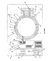
図1は、本発明が有利に実施され得る、従来の自動化学分析装置10の要素を模式的に示す。分析装置10は、キュベット17を支える外側キュベット円14を有する反応回転ラック12及びキュベット19を支える内側キュベット円16、溝18によって分離された外側キュベット円14と内側キュベット円16を含む。反応回転ラック12は階段状の動きを用いて、一定方向に一定速度で回転可能であり、この階段状の動きは、一定の滞留時間によって分離され、その滞留時間中、回転ラック12が静止状態に保持され、そしてセンサー、試薬添加位置、混合位置などの個別のコンピュータ制御された電気機械装置20が、周知の臨床分析において要求された作用を実行する。温度制御された試薬保存領域24と26は、与えられた分析を実行するために必要となるプローブ28及び30によってキュベット17及び19に置かれた試薬を含有する複数の試薬容器を保存する。種々のアッセイ分析手段22を、回転ラック14及び16に隣接して置くことができ、そしてキュベット17及び19において吸収され、又はそれらから発せられる種々の波長での光を測定するために適応させることができ、それによってサンプル液中の検体の存在を既知の分析技術を用いて求めることができる。
Detailed Description of the Invention FIG. 1 schematically illustrates elements of a conventional automated
そのような装置並びにそれらの制御及び操作が、例えば、米国特許第5,876,668号、第5,575,976号及び第5,482,861号、及びそれらの中に引用された文献において述べられており、実施のために参照することによって、それらが全て組込まれている。 Such devices and their control and operation are described, for example, in US Pat. Nos. 5,876,668, 5,575,976 and 5,482,861, and references cited therein. All of which are described and incorporated by reference for implementation.
分析装置10は、イリノイ州、DeerfirldのDade Behring社によって販売され、そして、患者サンプルの同定、分析要求などが与えられた分析及び関連する操作を実施するための、コンピュータに基づく電気機械制御プログラミングの当業者によって広く使用されているDimension(登録商標)臨床化学分析装置上で使用されるような、機械言語で書かれたソフトウエアに基づいて、コンピュータ15によって制御される。
The
試験されるべく入ってくるサンプルは、一般的には図2に見られるようなサンプルチューブラック42中に支えられ、そして、入ってくるレーン36A及び出て行くレーン36Bを含むサンプルチューブラック移動システム36によって移動可能なサンプル容器又はチューブ40中に含まれる。アリコートプローブ44は、サンプルチューブ40から液体サンプルを吸引するために、そして必須分析を実施するために要求され、そして分析装置10によって保有されるべき少なくとも一つのアリコート部分を供するために、サンプルの量に応じて、プローブ27を用いて、アリコート移動システム48上に運ばれたアリコート列46に、元の患者サンプルの一つ又はそれより多くのアリコート部分を分注するために、従来はコンピュータ15によって制御されている。
An incoming sample to be tested is generally supported in a
本分析装置において、オペレーターは、特定のサイズ及び形状のサンプルチューブク40を、特定のサンプルラック42内の事前に定められたスロット又は開口部41の中に置くこと、及びマーキングがチューブ40に適切に貼られ、そして読み取ることができるようにラック42において向いていることを確かめることを要求される。これらのマーキングは一般的に一次元の直線状である。これらの要求の目的は、分析装置内でチューブを追跡すること、及び吸引モード(速度、深さ、栓を貫通するか否かなど)を制御することを可能ならしめることである。明らかな理由から、オペレーターが如何なるチューブ40も如何なるラック42中の如何なる場所にも置ける自由度を有し、そしてその他の制約からも解放されることが非常に望ましい。
In this analyzer, an operator places a
本発明は、挿入物を同定して、種々の高さと直径のサンプルチューブ40を共通の吸引レベルに位置付けるために、特別な、高コントラストの反射性二次元(2−D)マーキングを有する多くの異なる挿入物を使用し、そうすることによってチューブのタイプも同定する。二次元のマーキングを読み、そしてサンプルチューブの種々の識別形状を分析するために、二次元撮像装置54が使用される。特に、撮像装置54、鏡52及び不透明反射鏡55、並びに点線のRADとして示される識別放射経路の相対的位置を示す、視覚システム50の概略斜視図である図3、及び図4の簡略化された上部平面図において例示された本発明の視覚システム50を用いて、サンプルチューブ40が走査される。撮像装置54は、図4の簡略化された概略上部平面図において見られるような、ラック42中に潜在的に存在する、種々の試験管40のタイプを同定するための640×480画素解像度を有する二次元CMOS撮像装置54のようなものである。CMOS撮像装置54のような撮像装置は、JADEK Technologies社からキット1090として入手でき、そしてそのような視覚キットは通常、遠隔ホストコンピュータ上で又は場合によりコンピュータ15上で実行される同定ソフトウエアプログラムを含む。データの保存記録、通信、加工、測定、分析、ファイル保管、報告及び印刷ための全てのユーティリティを供するための、広範な強化及び測定ツールを有する画像分析ソフトウエアは公知であり、ミッドランド州、BethesdaのMedia Cybernetic社及びニューヨーク州、BrooklynのShapImage Software社などの企業から市販品として入手できる。反射鏡55がラック42内のラックチューブ開口部又はスロット中に保持されたサンプルチューブ40上の2列の間に置かれた状態で示されており、ここで反射鏡55は不透明であり、そしてチューブ形状の画像処理に対して一貫した背景を供する対向する逆反射表面を含む。逆反射表面は砕かれたガラスビーズを含み、保護積層物で覆われており、イリノイ州、Lake VillaのID Label社などの企業から市販品として入手できる。
The present invention provides a number of special high-contrast reflective two-dimensional (2-D) markings for identifying inserts and
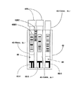
本発明の視覚システム50の重要な特徴は、図5に例示されたような、多くの特別にマーキングされたサンプルチューブ挿入物60であり、そして各々の異なる挿入物60はそこに貼られた独特の三次元マーキング62を有し、そして挿入物は、種々の高さと直径のチューブ40を共通の吸引レベルに配置するように高さを変えるものである。一つの実施態様において、この三次元マーキング62には、一本の水平ガイドバー66から垂れ下がっている、黒い等間隔の0〜3個の垂直データバー64が挿されている。挿入物60のタイプと存在を同定するために、垂直データバー64の有無が視覚システム50によって定められる。典型的な実施態様において、各々の垂直データバーは、幅が約0.05インチであり、そしてマーキング62の底まで延びる高さを有し、マーキング62は高さが約0.3インチで、幅が約0.9インチである。3つのデータバー64を用いると、下表1に示されるように、最大数で8つの異なるタイプの挿入物が同定可能となる。
An important feature of the

図5は、どのように三次元マーキング62が、水平ガイドバー66から垂れ下がっている垂直データバー64に挿されているかを例示しており、そしてまた、異なる三次元マーキング62に対応する異なるチューブタイプも示している。実際に、オペレーターは、そこに貼られた適切な三次元マーキング62を有する挿入物60を、ラック42中のチューブ開口部内に、そこにチューブ40を置く前に、簡単に置くことになる。例えば、もし患者のサンプルが(長さが100mmの「背が高い」チューブとは対照的に)長さが約75mmの「短い」直径13mmの主チューブ40中に含まれるならば、001(図5における上から2番目)として挿されているマーキング62を有する挿入物60が、チューブ40がその中に置かれるより前に、ラック42内のチューブ開口部に挿されるであろう。垂直データバー64のパターンの選択及びチューブ40の指示された異なるタイプとの関連は特別なものでもなく、またマーキング62とチューブ40に関しても制限されるもので
もない。視覚システム50と関連する同定ソフトウエアプログラムによって、マーキング62を適切に配置して同定するための助けとして、水平ガイドバー66が供される。マーキング62は、3M(登録商標)ScotchLite(登録商標)Plus Reflective Graphic Film Series 680として入手可能な、永久的な感圧性粘着剤層を有する柔軟な逆反射シート上に平らな黒インクを用いて有利にスクリーン印刷される。
FIG. 5 illustrates how the three-
図6と7は、種々のサンプルラック42、チューブ40、マーキング62、チューブ40上の栓40Sの有無の例を示している。図6は特に、011として挿された三次元マーキング62−1を持つ挿入物60を有する、栓付きの「短い」小児用チューブ40−10mm−sht上、並びに001として挿された三次元マーキング62−3を有する栓無しの「短い」13mm主チューブ40−13mm−sht上のチューブバーコード40BCを例示している。また、ラック42がラック同定バーコード42BCでラベルされたものとして見られる。図7はラック42の左端の開口部が空で、右端の開口部がMicro Sample Cup40−MSCの下に置かれた挿入物60−4を有し、挿入物60−4が、図5に合せて、101として挿されている三次元マーキング62−MSCでマーキングされている例を示している。
6 and 7 show examples of the presence or absence of
典型的な実施態様において、サンプルラック42は、ラック42の各々のサイドで3個の、最大で6個の試験管40を運ぶ。移送システム36は、一般的には照明用の赤色LEDを使用する一対の撮像装置54から発せられる識別放射線RADが、分析のために、チューブ40の暴露表面から反射されて撮像装置54に戻るように、そして注目の各々の試験管40が斜めに配置された一対の前部表面鏡52の間の中心にくるように、各ラック42を延ばされた円形パターンにスライドさせる。従来のソフトウエア同定技術を用いて、撮像装置54はマーキング62の二次元VGA画像を保存記録して、試験管40の同定のためにその画像を加工する。この第一チューブ40に対して画像処理が完了した後、移送システム36は、ラック42中の次の試験管40が鏡52の間の中心にくるように、ラック42を動かし、そして画像処理が繰返される。
In the exemplary embodiment,
ラック42側に置かれた撮像装置54に対してラック42の方向は、試験管40がその際に見えるように、鏡52が反射を供することが必要である。
The direction of the
視覚システム50の最適操作には、注目の試験管42に対して撮像装置54の適切な向き及びセンタリングが必要である。適正な検出処理に対しては、試験管42が撮像装置54によって撮られた画像の中心に位置することが有利である。鏡52、ラック42及び撮像装置54が視覚システム50内で確実に適切な配置となるために較正プロセスが使用される。この較正プロセスは従来の画像処理において使用される工程と同様であり、以下を定める:
1.反射鏡55の開始の画素位置;
2.反射鏡55上の逆反射領域の幅;及び
3.反射鏡55に関する挿入物60のオフセット寸法。
Optimal operation of the
1. Starting pixel position of
2. 2. the width of the retroreflective area on the
反射鏡55の逆反射端部の画素位置が、Cap/No Cap処理のために視覚システム50によって使用される。一旦、この値が決められると、それが次回の使用のために視覚システム50内部のフラッシュメモリ中に保存される。異なる値、逆反射開始位置の画素位置及び逆反射領域の幅がコンピュータ15に情報を供して、それらが鏡52及び/又は撮像装置54の適切な水平及び垂直配置を可能ならしめることになる。維持されるべきそしてまた較正されるべき領域の公知の幅があるであろう。また、調節されねばならない逆反射開始線の公知の画素位置があるであろう。ホストコンピュータ15は異なる値に対して視覚システム50に問い正すであろう。この値によって、試験管ラック42を正しい水平位置に動かすことが可能となる。本発明の実施において、遠隔コンピュータ15も使用され得る。
The pixel position of the retro-reflecting end of the
上の記述から、視覚システム50は、サンプルチューブ40及びサンプルラック42上のバーコード、挿入物60上のマーキング62、ラック42内のサンプルチューブ40の有無、サンプルチューブ40の蓋をする栓40Sの有無を同定して解読できるよう、そしてチューブ及びカップを含む多くの異なるタイプのサンプル容器を同定できるよう、撮像及び分析能力を供する。
From the above description, the
本発明の視覚システム50を用いて、以下を含む多くの他の利点も達成される:
1.「小さい」又は「マイクロサンプルカップ」の場合、蒸発低減蓋が閉じた位置にあり、そして、液体サンプルの全量を吸引するよう、適切に吸引を支配していることが、二次元撮像装置54によって場合により確認できる。また、オペレーターがバーコードを付けられたサンプルチューブから「マイクロサンプルカップ」にサンプルを注入する時に、サンプルチューブの信頼できる同定/追跡手段として、「サンプルカップ」上に置かれることになる二次元バーコードを自動的に印刷するよう、二次元バーコードプリンターがプログラム化され得る。
2.二次元撮像装置54が、サンプルを含有するラックチューブ開口部又はスロットにおいて読取れないマーキングを見つけた場合、オペレーターに問題を警告するエラーが掲示され得る。これにより、チューブ上の拙い印刷又は悪い位置のマーキングから生じる「紛失サンプル」が無くなる。
Many other advantages are also achieved using the
1. In the case of a “small” or “microsample cup”, the two-
2. If the
当業者は、本発明が広い実用性と用途に可能なことを容易に理解できるであろう。ここに述べられた以外の、本発明の多くの実施態様及び適応、並びに多くの変更、修正及び同等のアレンジが、本発明の本質又は範囲から逸脱することなく、本発明及びその前述の記載から明らかであり、又は合理的に示唆されるであろう。 Those skilled in the art will readily understand that the present invention is capable of wide utility and application. Many embodiments and adaptations of the present invention, and numerous changes, modifications and equivalent arrangements other than those described herein can be derived from the present invention and its foregoing description without departing from the spirit or scope of the invention. It will be obvious or reasonably suggested.
従って、特定の実施態様に関して本発明がここに詳細に述べられているものの、この開示は本発明の単なる例示及び典型例であり、単に発明の完全かつ実施可能な開示を供する目的でなされたと理解されるべきである。前述の開示は本発明を制限することを意図したものでもなく、解釈されるものでもなく、或いはその反対にそのような他の如何なる実施態様、適応、変更、改良及び同等のアレンジを排除するものでもなく、本発明はここに添付された請求の範囲及びそれらの同等物によってのみ制限される。 Thus, while the invention has been described in detail herein with reference to specific embodiments, it is understood that this disclosure is merely illustrative and exemplary of the invention and is provided solely for the purpose of providing a complete and practicable disclosure of the invention. It should be. The foregoing disclosure is not intended to be construed as limiting the present invention, nor is it intended to exclude any such other embodiments, adaptations, modifications, improvements and equivalent arrangements, on the contrary. Rather, the invention is limited only by the claims appended hereto and their equivalents.
Claims (13)
少なくとも一つの該開口部中のサンプルチューブ挿入物、ここでこの挿入物は、少なくとも一つの該開口部中のサンプルチューブのタイプを同定するために、その上に異なるマーキングを有し、マーキングが多くの垂直のバーを含み、マーキングが水平バーから垂れ下がっている;
該サンプルチューブラックに近接して配置された撮像装置、ここでこの装置は、該挿入物上のマーキングを同定するためにプログラム化されている;
を含む臨床分析装置において使用するための自動視覚システム。A sample tube rack having at least one row of openings capable of accommodating different types of sample tubes;
At least one sample tube insert in the opening, wherein the insert is to identify the type of sample tubes in at least one opening, have a different markings thereon, many marking Including vertical bars and the markings hang from the horizontal bars;
An imaging device positioned proximate to the sample tube rack, wherein the device is programmed to identify markings on the insert;
An automated vision system for use in clinical analyzers including:
該挿入物が、チューブを運ぶことができるラックにおける開口部に、取外せるように取り付けることができ;
該異なるマーキングが、異なるタイプのチューブと独特の方法で関連付けられており、マーキングが多くの垂直のバーを含み、マーキングが水平バーから垂れ下がっている;
ことを特徴とするチューブ挿入物。A plurality of tube inserts with different markings thereon,
The insert can be removably attached to an opening in a rack capable of carrying tubes;
The different markings are associated in a unique way with different types of tubes , the markings include many vertical bars, and the markings hang from the horizontal bars;
A tube insert characterized by that.
される撮像装置を含み、この装置は、該挿入物上のマーキングを同定するためにプログラム化されている、上記臨床分析装置。A clinical analyzer having an automatic vision system installed thereon, the analyzer analyzing a patient sample carried in a sample tube rack having openings for accommodating different types of sample tubes The sample tube rack also has a sample tube insert in at least one of the openings, the insert in a unique way to at least one type of sample tube in the opening. Having different markings for identification , the markings include a number of vertical bars, and the markings hang from the horizontal bars ; where the vision system includes an imaging device positioned proximate to the sample tube rack The device comprises a clinical analysis device programmed to identify a marking on the insert. .
Applications Claiming Priority (5)
| Application Number | Priority Date | Filing Date | Title |
|---|---|---|---|
| US82433706P | 2006-09-01 | 2006-09-01 | |
| US60/824,337 | 2006-09-01 | ||
| US11/846,666 US7988933B2 (en) | 2006-09-01 | 2007-08-29 | Identification system for a clinical sample container |
| US11/846,666 | 2007-08-29 | ||
| PCT/US2007/077184 WO2008028009A2 (en) | 2006-09-01 | 2007-08-30 | Identification system for a clinical sample container |
Publications (3)
| Publication Number | Publication Date |
|---|---|
| JP2010502961A JP2010502961A (en) | 2010-01-28 |
| JP2010502961A5 JP2010502961A5 (en) | 2010-09-24 |
| JP5011391B2 true JP5011391B2 (en) | 2012-08-29 |
Family
ID=39136861
Family Applications (1)
| Application Number | Title | Priority Date | Filing Date |
|---|---|---|---|
| JP2009526904A Expired - Fee Related JP5011391B2 (en) | 2006-09-01 | 2007-08-30 | Identification system for clinical sample containers |
Country Status (4)
| Country | Link |
|---|---|
| US (1) | US7988933B2 (en) |
| EP (1) | EP2069745A4 (en) |
| JP (1) | JP5011391B2 (en) |
| WO (1) | WO2008028009A2 (en) |
Cited By (1)
| Publication number | Priority date | Publication date | Assignee | Title |
|---|---|---|---|---|
| US8697865B2 (en) | 2004-05-21 | 2014-04-15 | Takeda Pharmaceutical Company Limited | Cyclic amide derivative, and its production and use |
Families Citing this family (26)
| Publication number | Priority date | Publication date | Assignee | Title |
|---|---|---|---|---|
| US9872815B2 (en) * | 2006-06-22 | 2018-01-23 | Maria Lourdes Rivero | Rack and method for facilitating medication-related information |
| EP2148205B1 (en) * | 2008-07-25 | 2013-01-02 | F. Hoffmann-La Roche AG | A method and laboratory system for handling sample tubes and an image analysing unit |
| EP2230520A1 (en) * | 2009-03-18 | 2010-09-22 | Koninklijke Philips Electronics N.V. | Cartridge for accommodating a sample including a sample information element |
| EP2749887A3 (en) | 2010-07-23 | 2014-10-01 | Beckman Coulter, Inc. | System Or Method Of Including Analytical Units |
| BR112014011043A2 (en) | 2011-11-07 | 2017-06-13 | Beckman Coulter Inc | specimen container detection |
| BR112014010955A2 (en) | 2011-11-07 | 2017-06-06 | Beckman Coulter Inc | system and method for processing samples |
| US9482684B2 (en) | 2011-11-07 | 2016-11-01 | Beckman Coulter, Inc. | Centrifuge system and workflow |
| JP2014532881A (en) | 2011-11-07 | 2014-12-08 | ベックマン コールター, インコーポレイテッド | Magnetic braking for specimen transport systems |
| US9446418B2 (en) | 2011-11-07 | 2016-09-20 | Beckman Coulter, Inc. | Robotic arm |
| EP3373015A1 (en) | 2011-11-07 | 2018-09-12 | Beckman Coulter Inc. | Aliquotter system and workflow |
| JP5993576B2 (en) * | 2012-01-05 | 2016-09-14 | あおい精機株式会社 | Specimen information detection apparatus and specimen information detection method |
| WO2015191702A1 (en) * | 2014-06-10 | 2015-12-17 | Siemens Healthcare Diagnostics Inc. | Drawer vision system |
| WO2017070663A1 (en) | 2015-10-23 | 2017-04-27 | Gen-Probe Incorporated | Systems and methods for reading machine-readable marks on racks and receptacles |
| JP6719901B2 (en) * | 2015-12-28 | 2020-07-08 | あおい精機株式会社 | Sample processing device |
| CH712734A1 (en) * | 2016-07-22 | 2018-01-31 | Tecan Trading Ag | Recognition device and method for detecting labels and / or features of laboratory objects. |
| US10179334B2 (en) | 2016-07-29 | 2019-01-15 | Heathrow Scientific Llc | Universal pipette stand |
| CN117058415A (en) | 2016-10-28 | 2023-11-14 | 贝克曼库尔特有限公司 | Substance preparation evaluation system |
| US10427162B2 (en) | 2016-12-21 | 2019-10-01 | Quandx Inc. | Systems and methods for molecular diagnostics |
| US11215628B2 (en) | 2017-06-21 | 2022-01-04 | Abbott Molecular Inc. | Methods of automatized sample loading and processing and devices and systems related thereto |
| JP7087058B2 (en) * | 2017-07-11 | 2022-06-20 | シーメンス・ヘルスケア・ダイアグノスティックス・インコーポレーテッド | Image-based tube head circle detection using multiple candidates |
| US10598637B2 (en) * | 2017-07-18 | 2020-03-24 | Perkinelmer Health Sciences, Inc. | Automated thermal desorption systems configured to determine sample tube orientation and/or cap presence, and related methods |
| US10816516B2 (en) | 2018-03-28 | 2020-10-27 | Perkinelmer Health Sciences, Inc. | Autosamplers and gas chromatographic systems and methods including same |
| CN109055203A (en) * | 2018-09-21 | 2018-12-21 | 中国人民解放军军事科学院军事医学研究院 | A kind of full-automatic biological chips work station and its detection method |
| CN109374909A (en) * | 2018-09-26 | 2019-02-22 | 苏州长光华医生物医学工程有限公司 | A kind of rotating disc type sample loading apparatus |
| CN111366738A (en) * | 2018-12-26 | 2020-07-03 | 北京普利生仪器有限公司 | In-vitro diagnosis device, sample introduction method and adapter |
| CN113049845A (en) * | 2019-12-28 | 2021-06-29 | 深圳市帝迈生物技术有限公司 | Automatic sample introduction device |
Family Cites Families (29)
| Publication number | Priority date | Publication date | Assignee | Title |
|---|---|---|---|---|
| US4729661A (en) | 1985-07-29 | 1988-03-08 | Specialty Medical Industries, Inc. | Asynchronous serial cuvette reader |
| US4944924A (en) | 1987-06-11 | 1990-07-31 | Technicon Instruments Corporation | Test tube holder |
| US4805772A (en) | 1988-02-26 | 1989-02-21 | Eastman Kodak Company | Adaptors for use with various containers bearing bar code labeling |
| US5201232A (en) * | 1988-12-29 | 1993-04-13 | Technicon Instruments Corporation | Integrated sampler for closed and open sample containers |
| DE4023194A1 (en) | 1990-07-20 | 1992-01-23 | Kodak Ag | DEVICE WITH SEVERAL RECEIVER ARRANGEMENTS FOR LIQUID-FILLED CONTAINERS |
| US5137693A (en) * | 1990-07-30 | 1992-08-11 | Miles Inc. | Spring biased test tube holder |
| JPH04172250A (en) * | 1990-11-05 | 1992-06-19 | Hitachi Ltd | Automatic analyzer having sample-container discriminating function |
| JPH0694728A (en) * | 1992-09-09 | 1994-04-08 | Shimadzu Corp | Sample pallet of clinical examination device |
| JP3350163B2 (en) * | 1993-06-25 | 2002-11-25 | 株式会社カイノス | Extraction container holding transfer device |
| US5456887A (en) | 1994-05-27 | 1995-10-10 | Coulter Corporation | Tube adapter |
| US5517867A (en) * | 1994-07-15 | 1996-05-21 | E. I. Du Pont De Nemours And Company | Liquid extraction apparatus |
| JPH08240594A (en) * | 1995-03-01 | 1996-09-17 | Toshiba Corp | Sampler system for chemical analysis apparatus |
| US5700429A (en) | 1995-04-19 | 1997-12-23 | Roche Diagnostic Systems, Inc. | Vessel holder for automated analyzer |
| US5672317A (en) | 1995-04-19 | 1997-09-30 | Roche Diagnostics Systems, Inc. | Analyzer with fixed position bar code reader |
| US5687849A (en) | 1996-04-23 | 1997-11-18 | Coulter International Corp. | Test tube cassette for accommodating different tube sizes |
| JP3032159B2 (en) * | 1996-09-24 | 2000-04-10 | 株式会社日立製作所 | Analysis system |
| FR2764704B1 (en) | 1997-06-16 | 1999-08-20 | Stago Diagnostica | DEVICE FOR THE AUTOMATIC READING OF AN IDENTIFICATION CODE CARRIED BY TUBULAR CONTAINERS |
| US6141602A (en) * | 1997-09-25 | 2000-10-31 | Hitachi, Ltd. | Specimen processing system |
| EP1058908A4 (en) * | 1997-12-08 | 2002-07-24 | Alexander R Roustaei | Single chip symbology reader with smart sensor |
| JP2000009736A (en) * | 1998-06-24 | 2000-01-14 | Aloka Co Ltd | Dispensation device |
| US20040252299A9 (en) | 2000-01-07 | 2004-12-16 | Lemmo Anthony V. | Apparatus and method for high-throughput preparation and spectroscopic classification and characterization of compositions |
| JP4527249B2 (en) * | 2000-07-10 | 2010-08-18 | 興和株式会社 | Cuvette management device and management method using the same |
| JP3527904B2 (en) | 2002-02-28 | 2004-05-17 | 照明 伊藤 | Test tube holder |
| EP1477226A1 (en) * | 2003-05-13 | 2004-11-17 | The Automation Partnership (Cambridge) Limited | Test tube for storing fluid |
| PL1678509T3 (en) * | 2003-10-28 | 2008-09-30 | Diesse Diagnostica Senese S P A | Device for performing analyses on biological fluids and related method |
| JP2005300302A (en) * | 2004-04-09 | 2005-10-27 | Tosoh Corp | Lighting system and reading device |
| US20060000296A1 (en) | 2004-07-02 | 2006-01-05 | Salter Jason P | Synchronization of sample and data collection |
| DE602004008759T2 (en) | 2004-07-06 | 2008-06-12 | Roche Diagnostics Gmbh | Stand system with adapter |
| US7569190B2 (en) * | 2006-09-05 | 2009-08-04 | Siemens Healthcare Diagnostics Inc. | Micro-sample cup rack adapter |
-
2007
- 2007-08-29 US US11/846,666 patent/US7988933B2/en active Active
- 2007-08-30 WO PCT/US2007/077184 patent/WO2008028009A2/en active Application Filing
- 2007-08-30 JP JP2009526904A patent/JP5011391B2/en not_active Expired - Fee Related
- 2007-08-30 EP EP07841586A patent/EP2069745A4/en not_active Ceased
Cited By (1)
| Publication number | Priority date | Publication date | Assignee | Title |
|---|---|---|---|---|
| US8697865B2 (en) | 2004-05-21 | 2014-04-15 | Takeda Pharmaceutical Company Limited | Cyclic amide derivative, and its production and use |
Also Published As
| Publication number | Publication date |
|---|---|
| US7988933B2 (en) | 2011-08-02 |
| EP2069745A2 (en) | 2009-06-17 |
| JP2010502961A (en) | 2010-01-28 |
| WO2008028009A3 (en) | 2008-12-04 |
| EP2069745A4 (en) | 2010-11-03 |
| US20080056958A1 (en) | 2008-03-06 |
| WO2008028009A2 (en) | 2008-03-06 |
Similar Documents
| Publication | Publication Date | Title |
|---|---|---|
| JP5011391B2 (en) | Identification system for clinical sample containers | |
| US9117192B2 (en) | Method for reading machine-readable labels | |
| US5663545A (en) | Labware identification system | |
| JP6076257B2 (en) | System and method for tracking articles during a process | |
| ES2216260T3 (en) | UNIVERSAL MACHINE FOR CLINICAL ANALYSIS. | |
| US20090028754A1 (en) | Insert for Restraining Tube Rotation in a Sample Tube Rack | |
| JP7109920B2 (en) | Systems and methods for reading machine-readable indicia on sample containers | |
| JP2014526687A5 (en) | ||
| JP2008532048A (en) | Automatic analyzer | |
| ES2924760T3 (en) | Method to contain multiple types of diagnostic test consumables in a single random access container | |
| JP2010502988A (en) | Micro sample cup rack adapter | |
| WO2015138044A1 (en) | Combined chemiluminescence and elisa automated sample reader | |
| JPWO2020179246A1 (en) | Automatic analyzer | |
| JPH0894626A (en) | Automatic analyzer | |
| US11097277B2 (en) | Cover member with orientation indicia |
Legal Events
| Date | Code | Title | Description |
|---|---|---|---|
| A521 | Request for written amendment filed |
Free format text: JAPANESE INTERMEDIATE CODE: A523 Effective date: 20100803 |
|
| A621 | Written request for application examination |
Free format text: JAPANESE INTERMEDIATE CODE: A621 Effective date: 20100803 |
|
| A131 | Notification of reasons for refusal |
Free format text: JAPANESE INTERMEDIATE CODE: A131 Effective date: 20120221 |
|
| A977 | Report on retrieval |
Free format text: JAPANESE INTERMEDIATE CODE: A971007 Effective date: 20120222 |
|
| A521 | Request for written amendment filed |
Free format text: JAPANESE INTERMEDIATE CODE: A523 Effective date: 20120419 |
|
| TRDD | Decision of grant or rejection written | ||
| A01 | Written decision to grant a patent or to grant a registration (utility model) |
Free format text: JAPANESE INTERMEDIATE CODE: A01 Effective date: 20120522 |
|
| A01 | Written decision to grant a patent or to grant a registration (utility model) |
Free format text: JAPANESE INTERMEDIATE CODE: A01 |
|
| A61 | First payment of annual fees (during grant procedure) |
Free format text: JAPANESE INTERMEDIATE CODE: A61 Effective date: 20120604 |
|
| R150 | Certificate of patent or registration of utility model |
Free format text: JAPANESE INTERMEDIATE CODE: R150 |
|
| FPAY | Renewal fee payment (event date is renewal date of database) |
Free format text: PAYMENT UNTIL: 20150608 Year of fee payment: 3 |
|
| LAPS | Cancellation because of no payment of annual fees |