EP0979641B1 - Vorrichtung zum Überwachen einer Patientenbewegungsvorrichtung - Google Patents
Vorrichtung zum Überwachen einer Patientenbewegungsvorrichtung Download PDFInfo
- Publication number
- EP0979641B1 EP0979641B1 EP99303709A EP99303709A EP0979641B1 EP 0979641 B1 EP0979641 B1 EP 0979641B1 EP 99303709 A EP99303709 A EP 99303709A EP 99303709 A EP99303709 A EP 99303709A EP 0979641 B1 EP0979641 B1 EP 0979641B1
- Authority
- EP
- European Patent Office
- Prior art keywords
- frame
- trolley
- support portion
- moved
- positions
- Prior art date
- Legal status (The legal status is an assumption and is not a legal conclusion. Google has not performed a legal analysis and makes no representation as to the accuracy of the status listed.)
- Expired - Lifetime
Links
- 238000012544 monitoring process Methods 0.000 title claims description 8
- 238000000034 method Methods 0.000 claims description 15
- 230000000694 effects Effects 0.000 claims description 2
- 210000002414 leg Anatomy 0.000 description 42
- 235000014676 Phragmites communis Nutrition 0.000 description 4
- 230000001681 protective effect Effects 0.000 description 3
- 210000001217 buttock Anatomy 0.000 description 2
- 239000002184 metal Substances 0.000 description 2
- 230000000717 retained effect Effects 0.000 description 2
- 238000005096 rolling process Methods 0.000 description 2
- 230000002411 adverse Effects 0.000 description 1
- 230000005484 gravity Effects 0.000 description 1
- 238000003780 insertion Methods 0.000 description 1
- 230000037431 insertion Effects 0.000 description 1
- 238000007689 inspection Methods 0.000 description 1
- 230000000284 resting effect Effects 0.000 description 1
- 230000000452 restraining effect Effects 0.000 description 1
- 238000002560 therapeutic procedure Methods 0.000 description 1
- 210000001364 upper extremity Anatomy 0.000 description 1
- 238000011179 visual inspection Methods 0.000 description 1
Images


Classifications
-
- A—HUMAN NECESSITIES
- A61—MEDICAL OR VETERINARY SCIENCE; HYGIENE
- A61G—TRANSPORT, PERSONAL CONVEYANCES, OR ACCOMMODATION SPECIALLY ADAPTED FOR PATIENTS OR DISABLED PERSONS; OPERATING TABLES OR CHAIRS; CHAIRS FOR DENTISTRY; FUNERAL DEVICES
- A61G1/00—Stretchers
- A61G1/04—Parts, details or accessories, e.g. head-, foot-, or like rests specially adapted for stretchers
- A61G1/052—Struts, spars or legs
- A61G1/056—Swivelling legs
- A61G1/0565—Swivelling legs simultaneously folding, e.g. parallelogram structures
- A61G1/0567—Swivelling legs simultaneously folding, e.g. parallelogram structures folding in x-shape
-
- A—HUMAN NECESSITIES
- A61—MEDICAL OR VETERINARY SCIENCE; HYGIENE
- A61G—TRANSPORT, PERSONAL CONVEYANCES, OR ACCOMMODATION SPECIALLY ADAPTED FOR PATIENTS OR DISABLED PERSONS; OPERATING TABLES OR CHAIRS; CHAIRS FOR DENTISTRY; FUNERAL DEVICES
- A61G1/00—Stretchers
- A61G1/013—Stretchers foldable or collapsible
-
- A—HUMAN NECESSITIES
- A61—MEDICAL OR VETERINARY SCIENCE; HYGIENE
- A61G—TRANSPORT, PERSONAL CONVEYANCES, OR ACCOMMODATION SPECIALLY ADAPTED FOR PATIENTS OR DISABLED PERSONS; OPERATING TABLES OR CHAIRS; CHAIRS FOR DENTISTRY; FUNERAL DEVICES
- A61G1/00—Stretchers
- A61G1/02—Stretchers with wheels
- A61G1/0206—Stretchers with wheels characterised by the number of supporting wheels if stretcher is extended
- A61G1/0212—2 pairs having wheels within a pair on the same position in longitudinal direction, e.g. on the same axis
-
- A—HUMAN NECESSITIES
- A61—MEDICAL OR VETERINARY SCIENCE; HYGIENE
- A61G—TRANSPORT, PERSONAL CONVEYANCES, OR ACCOMMODATION SPECIALLY ADAPTED FOR PATIENTS OR DISABLED PERSONS; OPERATING TABLES OR CHAIRS; CHAIRS FOR DENTISTRY; FUNERAL DEVICES
- A61G1/00—Stretchers
- A61G1/02—Stretchers with wheels
- A61G1/0237—Stretchers with wheels having at least one swivelling wheel, e.g. castors
-
- A—HUMAN NECESSITIES
- A61—MEDICAL OR VETERINARY SCIENCE; HYGIENE
- A61G—TRANSPORT, PERSONAL CONVEYANCES, OR ACCOMMODATION SPECIALLY ADAPTED FOR PATIENTS OR DISABLED PERSONS; OPERATING TABLES OR CHAIRS; CHAIRS FOR DENTISTRY; FUNERAL DEVICES
- A61G1/00—Stretchers
- A61G1/02—Stretchers with wheels
- A61G1/025—Stretchers with wheels having auxiliary wheels, e.g. wheels not touching the ground in extended position
- A61G1/0256—Stretchers with wheels having auxiliary wheels, e.g. wheels not touching the ground in extended position having wheels which support exclusively if stretcher is in low position, e.g. on the folded legs
-
- A—HUMAN NECESSITIES
- A61—MEDICAL OR VETERINARY SCIENCE; HYGIENE
- A61G—TRANSPORT, PERSONAL CONVEYANCES, OR ACCOMMODATION SPECIALLY ADAPTED FOR PATIENTS OR DISABLED PERSONS; OPERATING TABLES OR CHAIRS; CHAIRS FOR DENTISTRY; FUNERAL DEVICES
- A61G1/00—Stretchers
- A61G1/02—Stretchers with wheels
- A61G1/025—Stretchers with wheels having auxiliary wheels, e.g. wheels not touching the ground in extended position
- A61G1/0262—Stretchers with wheels having auxiliary wheels, e.g. wheels not touching the ground in extended position having loading wheels situated in the front during loading
-
- A—HUMAN NECESSITIES
- A61—MEDICAL OR VETERINARY SCIENCE; HYGIENE
- A61G—TRANSPORT, PERSONAL CONVEYANCES, OR ACCOMMODATION SPECIALLY ADAPTED FOR PATIENTS OR DISABLED PERSONS; OPERATING TABLES OR CHAIRS; CHAIRS FOR DENTISTRY; FUNERAL DEVICES
- A61G1/00—Stretchers
- A61G1/04—Parts, details or accessories, e.g. head-, foot-, or like rests specially adapted for stretchers
- A61G1/052—Struts, spars or legs
- A61G1/056—Swivelling legs
- A61G1/0562—Swivelling legs independently foldable, i.e. at least part of the leg folding movement is not simultaneous
Definitions
- the present invention relates to patient handling equipment and to a method of monitoring patient handling equipment.
- Stretcher trolleys are frequently collapsed into a lower position and then raised again. Collapse normally occurs when the trolley is entering an ambulance and the trolley is normally raised when a patient is being manoeuvred on the trolley. Similarly chairs that are used to transport patients are frequently collapsed to a storage position when not in use.
- the raising and lowering of the trolleys subjects the trolleys to metal fatigue. Whilst trolleys are serviced regularly there is no way of making a visual inspection of the fatigue that the metal has suffered. Accordingly, good practice is to replace the trolleys when they are likely to have undergone a certain number of raising and lowering operations.
- trolleys When trolleys are sold they normally go, in a batch order, to a particular authority. That authority then allocates the stretchers either to inner city front line ambulance services, where the trolleys are subjected to frequent raising and lowering, or to suburban or rural services where frequency of use is far less. Nevertheless, good practice dictates that the trolleys are exchanged when fatigue may have occurred to an extent where replacement is required on the assumption that each trolley is an inner city trolley that has been subject to frequent raising and lowering. Alternatively trolleys are frequently kept in use beyond what is to be an acceptable or safe life span.
- EP 0 022 002 discloses a kinetic therapy table on which a patient lies. Movement of the patients leg and the direction of movement is controlled by a cabinet that is connected to the patients leg.
- patient handling apparatus is defined in Claim 1.
- the counting means may be arranged to provide a count when the support portion is moved to at least one of the positions.
- the counting means may be arranged to provide an indication of the number of times the support portion has been moved to the second position.
- the counting means may comprise first and second parts that are arranged to move relative to each other when the support portion has moved between the two positions. Relative movement of the first and second parts may be arranged to effect the count.
- the first part may comprise a magnet and the second part may comprise a counter responsive to the magnet, such as being responsive to movement of the magnet.
- the first and second parts may be arranged to be spaced from each other when the support portion is being moved between the first and second positions and when the support portion is in the first and second positions and monitoring that indication.
- the first and second parts may both be arranged to move.
- One part may move translationally.
- at least one and preferably both parts may move pivotally.
- the parts may both be arranged to be mounted in the top region of a stretcher when that stretcher is in both positions.
- At least one and preferably both parts may be arranged to be located beneath the support portion.
- the first and second parts may be arranged to come within 10mm of each other in order to activate the counting means.
- the counting means may be arranged to record every alternative count.
- At least one of the first or second parts of the counting means may be mounted to move when the upper frame arrangement moves between the upper and lower positions.
- the trolley arrangement may include a second, lower frame arrangement that the upper frame arrangement is arranged to move towards and away from when the upper frame arrangement is being moved away from or towards the raised position.
- the upper frame arrangement may be arranged to be supported directly on the lower frame arrangement when the support portion is in the lower position.
- the upper frame arrangement and the lower frame arrangement may be connected together by a linkage arranged to control the movement between the upper and lower frame arrangements.
- At least part of the counting means may be concealed. At least part of the counting means may be located in part of a frame of the patient handling equipment or mounted on or to a part of a frame of the trolley arrangement. The part of the counting means that is located in part of the frame may be visible through part of the frame. Alternatively or additionally that part may be accessible by removing part of the frame such as a cover on part of the frame.
- a method of monitoring patient handling apparatus is defined in Claim 13.
- the trolley arrangement may include wheels that the trolley arrangement is moved on.
- the method may comprise periodically monitoring the number of times that the support portion has been moved between the upper and lower positions and causing an event to occur as a result of the number of times that a support portion has been moved to at least one of the positions, that event being, for instance, to provide a service for the apparatus, or to vary the service that is provided, or to recommend replacement of at least part of the apparatus.
- the method may comprise viewing a counter when the apparatus is being monitored and the method may comprise viewing the counter through a part of the apparatus or the method may comprise moving a part of the apparatus in order to view the counter.
- the method may comprise monitoring alternate counts.
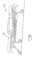
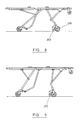
- the trolley 10 includes a support portion 12 defined by a back support portion 12a, a buttock support portion 12b and a leg support portion 12c.
- the angles of the back and leg support portions can be varied on the trolley by altering the angles of props that extend to beneath the support portion to the main frame of the trolley. The operation of such supports is well known and will not be described further.
- a mattress 14 can be located on the support portion 12, as shown in Figure 2.
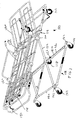
- the trolley includes an upper quadrilateral frame 16 and a lower quadrilateral frame 18.
- the frames 16 and 18 are connected together by a first leg frame 20 that is pivotally connected to an end section 18a of the lower frame and a second leg frame 22.
- the leg frame 22 is connected to the side sections 18b of the lower frame via blocks 24 connected to the side sections 18b.
- the legs 22 are connected to the block 24 via rollers 26 that permit the legs 22 to move relative to the blocks 24 to a limited degree between the ends of the blocks in the direction of extent of the side sections 18a.
- the leg frames 20 and 22 are connected together by a horizontal pivot rod 28.
- the upper end of the leg frame 22 is pivotally connected, at each side, to a bar 30.
- Each end of the bar 30 is connected via a shaft 32 to the side of the upper frame 16.
- the leg frame 22 is connected to the upper frame 16 by a sliding connection 34 in a well known manner such that, upon pulling of a handle 36 a lug restraining relative sliding movement is released from a slot 38 and the upper leg is able to slide towards or away from the end portion 16b of the upper frame.
- a lug restraining relative sliding movement is released from a slot 38 and the upper leg is able to slide towards or away from the end portion 16b of the upper frame.
- the spring loaded lug returns into the next slot 38 that it comes into alignment with.
- This sliding movement of the upper end of the leg frame 20 causes the height of the stretcher to be raised or lowered.
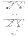
- sockets 40 are lowered on to spindles 42 of the upper frame and lower frame respectively, as shown in Figure 2. In that position the upper frame rests on the lower frame and the leg frames are substantially parallel to each other.
- the trolley can be manoeuvred by being rolled along wheels 44 which can rotate about a horizontal axis and also about a vertical axis depending downwardly from each corner of the lower frame.
- the trolley can approach an ambulance such that wheels 46, which can rotate about a horizontal axis and which are connected to the upper frame towards the front end 16b just below that end, rest on the floor of the ambulance.
- the wheels 46 can be arranged to be at a slightly greater height than the floor of the ambulance.
- the rear of the trolley can then be lifted to pivot the trolley about the wheels 44 and to bring the wheels 46 into contact with the floor of the ambulance.
- the lower frame is then brought up to the upper frame and detachably retained in position.
- the trolley is then pushed into the ambulance. Removal of the trolley from the ambulance and the lifting of the upper frame relative to the lower frame is a reversal of the above described sequence.
- the trolley includes an upper rectangular frame 116 of round cross-section tube and a lower rectangular frame 118 also of round cross-section tube.
- Two pairs of leg frames 120 and 122 are provided with those frames each being connected to two different end sections 118a.
- a pivot rod 128 connects the two frames.
- Back 112a, buttock 112b and leg 112c supports are provided which are connected to the upper frame 116. The position of the back and leg supports can be pivotally adjusted in a well known manner.
- a handle 136 at one end of the upper frame 116 can be pulled in the lengthwise direction of the trolley in order to move a locking bar (not shown) from a position in which it engages one pair of opposing slots to a position in which it is free of those slots. That rod is connected to the upper end of the frame 120. When the rod is clear of the slots the upper end of the frame 120 is free to slide towards or away from the end of the upper frame. This allows the trolley to be raised or lowered. When the handle 136 is released the bar, which is spring mounted, is resiliently biased back into engagement with the next pair of slots that it becomes aligned with. The trolley can be collapsed such that the leg frames 120 and 122 are substantially parallel with each other and with supports 40 on the upper frame resting on supports 142 at each corner of the lower frame.
- Each corner of the lower frame includes wheels 144 that roll about a horizontal pivot with each wheel in turn being supported by a housing that can pivot about a vertical axis at each corner of the lower frame.
- the front end of the upper frame also includes a pair of spaced wheels 146 at each side that are located just beneath the extent of the upper frame.
- the stretcher 110 can be inserted into and removed from an ambulance as described in relation to the stretcher 10 and can also be moved on the wheels 144 when the stretcher is in the collapsed position as described in relation to the stretcher 10.
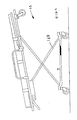
- Figure 4 shows the position that the stretcher can occupy, with the upper frame being inclined such that the front of the upper frame is higher than the lower end of the upper frame. That is achieved by pulling a lever (not shown) that allows the head and foot of the upper frame to be lowered by causing telescopic portions 148 of the leg frames 120 that extend between the pivot rod 128 and the lower end of the leg frame 120 to be extended. When the handle is released the telescopic portion is locked. When the handle is pulled again the head and foot portion can be pushed down to return the upper frame to the generally horizontal position.
- a patient is arranged to be located on a mattress supported in the region of an upper quadrilateral frame 212.
- the frame has a forward leg frame 214 and a rearward leg frame 216 to the lower end of which wheels 218 and 220 are mounted.
- the wheels 218 are constrained to rotate in one direction but the wheels 210 are able to pivot about a vertical axis.
- the leg frame 214 is pivotally connected to a block 222 that is able to slide on a rail 224 in the general direction of the elongate extent of the quadrilateral frame 212.
- the leg frame 214 is also, at a point intermediate of its upper and lower extent, pivotally connected to a strut frame 225 which, in turn, is mounted to the quadrilateral frame 212 at a pivot 228.
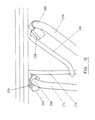
- the trolley To load the trolley into an ambulance the trolley is rolled on the wheels 218 in the direction of arrow 230.
- a protective cover 232 on the strut 226 hits the back of the ambulance and, after one of a pair of levers 233 has been pulled to release the sliding block 222, the strut is swung to the left by the abutment with the ambulance about the pivot 228.
- the front of the trolley is supported on the ambulance floor by a pair of wheels 236 that depend downwardly from the front of the quadrilateral frame 212.
- the block 222 slides forwardly on the rail to raise the leg frame 214 upwardly and rearwardly about its pivot on the block until the protective cover 234 on the leg frame 214 abuts the ambulance.
- the leg frame 214 and strut 226 Continued movement of the frame into the ambulance causes the leg frame 214 and strut 226 to collapse and extend generally parallel to the quadrilateral frame 212.
- leg frame 214 When the leg frame 214 is moving to its collapsed position the spaced parallel legs of the frame 214 move to be either side of parallel struts 238 that are pivotally connected to the bottom of the leg frame 216 and the quadrilateral frame 212 by a pivot 240.
- the rear leg frame 216 is slidably mounted on the rail by means of a block and the leg frame 216 is pivotally mounted on that block.
- the struts 238 move upwardly and rearwardly about the pivot 240 and the leg frame 216 also moves upwardly and rearwardly with the upper part of the leg frame sliding forwardly via the block on the rail.
- a strut 246 is pivotally connected to the leg frame 216 at a location between the ends thereof and is pivotally mounted on the quadrilateral frame. Eventually the leg frame is substantially coextensive with the quadrilateral frame 212 as wheels 248 on the struts 238 support and guide the rear of the trolley on the floor of the ambulance.
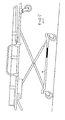
- Figures 8 and 9 show how the blocks on the rail can be moved to and retained in different positions on the rail in order to achieve different operational positions for the trolley.
- the legs have been pivoted slightly such that the quadrilateral frame remains horizontal but wheels 250 that can pivot about an axis perpendicular to their rolling axis engage with the ground.
- the wheels 250 are mounted at the bottom of the forward leg frame adjacent to the wheels 218.
- leg frame has been further collapsed such that the wheels 250 are just clear of the ground and, in Figure 10, the collapse is further on and the wheels 250 are well clear of the ground.
- Removal from an ambulance is a reversal of the insertion procedure except that the leg frames return under gravity when the relevant parts clear the rear of the vehicle.
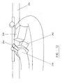
- a magnet 252 is secured to a clamp 254 which is bolted on to a cross bar 256 that connects the upper end of the front leg frame 214.
- a counter 258 is bolted on to a cross bar 260 that connects the spaced struts 226.
- the cross bar 256 moves forwardly on the rail and rotates in a clockwise direction and the cross bar 260 rotates in an anticlockwise direction. Consequently the magnet moves forwardly and rotates with the bar 256 and the counter rotates with the bar 260 to cause the magnet to sweep past the counter thereby causing a count to be recorded.
- the magnet sweeps past the counter and another count is recorded.
- the counter could be arranged to record every other count in order that the number recorded corresponds to the number of turns the stretcher is raised and lowered rather than recording each raising and lowering.
- a magnet 252 (or 252A in Figure 1) is mounted on the lower frame and a reed switch 258 is mounted on the upper frame.
- these parts could be mounted the other way round.
- the magnet does not come into contact with the reed switch but, in the lower position, the magnet would be within 10mm of the reed switch.
- a counter is tripped and the counter moves on one. Accordingly, the counter will record the number of times that the frame has been raised and lowered or, alternatively or additionally the number of times that the trolley has been loaded or unloaded into an ambulance.
- Either or both of the magnet and the reed switch in all embodiments can be concealed, it can be made weather-proof or can be made tamper-proof or both. In this way the counter is able to continue functioning and is not liable to be subjected to knocks that can push it out of line or detach it from the frame. Furthermore, the adverse whether conditions that the stretcher can be used in will not affect the operation of the counter and third parties are not able to access the counter.
- the counter may be located within a block which is mounted on either the lower or the upper frame in order to prevent tampering with the counter.
- the counter can be concealed in a tube of the frame.
- the tubes can be slid along in order to give access to the counter, the counter can be read and inspected and possibly have a battery replaced before the tube is moved back to conceal the counter again. If desired the tube can be secured in position with secure bolts.
- a service engineer reading the counter can determine either that the trolley is ready for a service because it has completed, for the sake of argument, two hundred cycles of raising and lowering.
- a service engineer can determine that the stretcher is due for replacement if, for the sake of argument, the stretcher has been raised and lowered a thousand times.
- Each trolley is assigned its own serial number and each counter may be given a corresponding serial number either directly on the counter or on the magnet or on a housing for the counter. In that way it will not be possible for counters to be switched from one trolley to another without a service engineer being aware of that switch.
Landscapes
- Life Sciences & Earth Sciences (AREA)
- Animal Behavior & Ethology (AREA)
- General Health & Medical Sciences (AREA)
- Public Health (AREA)
- Veterinary Medicine (AREA)
- Health & Medical Sciences (AREA)
- Handcart (AREA)
- Measuring And Recording Apparatus For Diagnosis (AREA)
- Apparatus For Radiation Diagnosis (AREA)
- Medical Preparation Storing Or Oral Administration Devices (AREA)
- External Artificial Organs (AREA)
- Accommodation For Nursing Or Treatment Tables (AREA)
- Invalid Beds And Related Equipment (AREA)
Claims (14)
- Patientenbewegungsvorrichtung bestehend aus einem Bahrenwagen einschließlich einer oberen Rahmenanordnung (16) verbunden mit einem Patientenauflagebereich (14), wobei die obere Rahmenanordnung und der verbundene Patientenauflagebereich zwischen einer ersten, oberen Position und einer zweiten, unteren Position beweglich ist, dadurch gekennzeichnet, dass der Bahrenwagen ein Zählmittel (252, 258) umfasst, das angeordnet ist um eine Anzeige über die Anzahl der Male die der obere Rahmen und der damit verbundene Patientenauflagebereich zu mindestens einer der ersten, oberen oder zweiten, unteren Position bewegt wurde, bereitzustellen
- Vorrichtung nach Anspruch 1, bei der das Zählmittel aus ersten und zweiten Teilen (252, 258) besteht, die so angeordnet sind, dass sie sich relativ zueinander bewegen, wenn der Auflagebereich zwischen den beiden Positionen bewegt wird.
- Vorrichtung nach Anspruch 2, bei der die Relativbewegung der ersten und zweiten Teile so angeordnet ist, dass der zählvorgang ausgelöst wird.
- Vorrichtung nach Anspruch 2 oder 3 bei der der erste Teil einen Magneten (252, 252a) enthält und der zweite Teil einen Zähler (258) der auf den Magneten anspricht enthält.
- Vorrichtung nach einem der Ansprüche 2 bis 4, bei der die ersten und zweiten Teile voneinander beabstandet angeordnet sind, wenn der Auflagebereich zwischen den ersten und zweiten Positionen bewegt wird und wenn sich der Auflagebereich in den ersten und zweiten Positionen befindet.
- Vorrichtung nach einem der Ansprüche 2 bis 5, bei der die ersten und zweiten Teile beide beweglich angeordnet sind.
- Vorrichtung nach einem der Ansprüche 2 bis 6, bei der sich mindestens ein Teil translatorisch bewegt.
- Vorrichtung nach einem der Ansprüche 2 bis 7, bei der sich mindestens ein Teil schwenkend bewegt.
- Vorrichtung nach den Ansprüche 2 bis 8, bei der mindestens ein Teil unter dem Auflagebereich platziert ist.
- Vorrichtung nach einem der vorangegangenen Ansprüche, bei der das Zählmittel ausgebildet ist, um jede alternative Zählung zu registrieren.
- Vorrichtung nach einem der vorangegangenen Ansprüche bei, der zumindest ein Teil des zählmittels verdeckt ist.
- Vorrichtung nach einem der vorangegangenen Ansprüche, bei der zumindest ein Teil des Zählmittels in einem Teil eines Rahmens der Patientenbewegungsvorrichtung platziert ist.
- Verfahren zur Überwachung einer Patientenbewegungsvorrichtung, die einen Bahrenwagen (10, 210) umfasst, wobei das Verfahren das Bewegen eines oberen Rahmens und einer damit verbundenen Patientenauflage von einer ersten, oberen Position in eine zweite, untere Position umfasst, dadurch gekennzeichnet, dass eine Anzeige (252, 258) der Anzahl der Male, die der obere Rahmen und die damit verbundene Patientenauflage zwischen der ersten und zweiten Position bewegt wurde, bereitgestellt ist.
- Verfahren nach Anspruch 13, umfassend das periodische Auslesen der Anzahl der Male, die der Auflageteil zwischen der oberen und unteren Position bewegt wurde, und das Auslösen eines Ereignisses aufgrund der Anzahl der Male, die der Auflageteil in mindestens eine der Positionen bewegt wurde.
Applications Claiming Priority (2)
| Application Number | Priority Date | Filing Date | Title |
|---|---|---|---|
| GB9810616 | 1998-05-19 | ||
| GB9810616A GB2337451B (en) | 1998-05-19 | 1998-05-19 | Monitoring patient handling equipment |
Publications (3)
| Publication Number | Publication Date |
|---|---|
| EP0979641A2 EP0979641A2 (de) | 2000-02-16 |
| EP0979641A3 EP0979641A3 (de) | 2000-07-19 |
| EP0979641B1 true EP0979641B1 (de) | 2007-01-24 |
Family
ID=10832234
Family Applications (1)
| Application Number | Title | Priority Date | Filing Date |
|---|---|---|---|
| EP99303709A Expired - Lifetime EP0979641B1 (de) | 1998-05-19 | 1999-05-12 | Vorrichtung zum Überwachen einer Patientenbewegungsvorrichtung |
Country Status (8)
| Country | Link |
|---|---|
| US (1) | US6219864B1 (de) |
| EP (1) | EP0979641B1 (de) |
| AT (1) | ATE352272T1 (de) |
| DE (1) | DE69934941T2 (de) |
| DK (1) | DK0979641T3 (de) |
| ES (1) | ES2279602T3 (de) |
| GB (1) | GB2337451B (de) |
| PT (1) | PT979641E (de) |
Cited By (1)
| Publication number | Priority date | Publication date | Assignee | Title |
|---|---|---|---|---|
| US9009893B2 (en) | 1999-12-29 | 2015-04-21 | Hill-Rom Services, Inc. | Hospital bed |
Families Citing this family (24)
| Publication number | Priority date | Publication date | Assignee | Title |
|---|---|---|---|---|
| US6497231B1 (en) * | 2000-03-24 | 2002-12-24 | White Perry La'monte | Hyperbaric oxygen chamber |
| IT1317334B1 (it) * | 2000-05-16 | 2003-06-16 | Vassilli Srl | Telaio, in particolare telaio di letto, variabile in altezza. |
| JP4712385B2 (ja) | 2002-09-06 | 2011-06-29 | ヒル−ロム サービシーズ,インコーポレイティド | 病院ベッド |
| DE602004029980D1 (de) * | 2003-01-15 | 2010-12-23 | Stryker Corp | Be- und entladungsvorrichtung für krankentragen für krankenwagen |
| US7140055B2 (en) * | 2003-07-18 | 2006-11-28 | Joseph Bishop | Lightweight mobile lift-assisted patient transport device |
| US7073219B2 (en) * | 2004-01-06 | 2006-07-11 | Teknion Concept | Side rail, hospital bed including the same, method of operating associated thereto and kit for assembling the side rail |
| BRPI0512067B8 (pt) | 2004-06-14 | 2021-06-22 | Ferno Washington | maca de ambulância com elevador acionado hidraulicamente |
| US7521891B2 (en) * | 2004-06-14 | 2009-04-21 | Fernon-Washington, Inc. | Charging system for recharging a battery of powered lift ambulance cot with an electrical system of an emergency vehicle |
| CA2472491C (en) * | 2004-06-25 | 2011-05-24 | Carroll Hospital Group Inc. | Leveling system for a height adjustable patient bed |
| US7003829B2 (en) * | 2004-07-26 | 2006-02-28 | Byung Ki Choi | Stretcher with gear mechanism for adjustable height |
| US7398571B2 (en) * | 2004-09-24 | 2008-07-15 | Stryker Corporation | Ambulance cot and hydraulic elevating mechanism therefor |
| EP1799171B1 (de) * | 2004-09-24 | 2014-04-16 | Stryker Corporation | Ambulanz-kinderbett und hydraulischer Hebemechanismus dafür |
| GB2427699A (en) * | 2005-04-09 | 2007-01-03 | Smarta Systems Ltd | Overload monitoring system |
| GB0513227D0 (en) | 2005-06-29 | 2005-08-03 | Ferno Uk Ltd | Stretcher |
| GB2444237A (en) * | 2006-12-01 | 2008-06-04 | Ferno | Collapsible strectcher |
| USD554261S1 (en) * | 2006-12-04 | 2007-10-30 | Rudy Meoli | ER cot |
| WO2009085332A1 (en) * | 2007-12-31 | 2009-07-09 | Monster Medic, Inc. | Ambulance cot system |
| US7389552B1 (en) | 2007-12-31 | 2008-06-24 | Monster Medic, Inc. | Ambulance cot system |
| US8051511B2 (en) * | 2008-01-14 | 2011-11-08 | Stryker Corporation | Emergency stretcher |
| JP5486506B2 (ja) * | 2008-11-07 | 2014-05-07 | 株式会社松永製作所 | ストレッチャー |
| US9510981B2 (en) * | 2013-03-14 | 2016-12-06 | Stryker Corporation | Reconfigurable transport apparatus |
| US9603764B2 (en) | 2014-02-11 | 2017-03-28 | Medline Industries, Inc. | Method and apparatus for a locking caster |
| US9768397B2 (en) * | 2014-03-31 | 2017-09-19 | Commonwealth Scientific And Industrial Research Organisation | Phenylenediamine compounds for phosphorescent diazaborole metal complexes |
| DE102019118869B4 (de) * | 2019-07-11 | 2021-01-21 | Aesculap Ag | Vorrichtung zur Erfassung von Betätigungszyklen eines handbetätigten Instruments |
Family Cites Families (6)
| Publication number | Priority date | Publication date | Assignee | Title |
|---|---|---|---|---|
| GB1350068A (en) * | 1970-06-23 | 1974-04-18 | Stewart J S S | Physiotherapy control device |
| US4233844A (en) * | 1978-12-21 | 1980-11-18 | Cardrei Corporation | Wheelchair ergometer |
| US4207770A (en) * | 1979-05-07 | 1980-06-17 | Gerald Grushow | Change of direction sensing mechanism |
| FR2459040A1 (fr) * | 1979-06-20 | 1981-01-09 | Barnet Alain | Appareil de kinesitherapie, notamment pour les traitements de reeducation |
| JP3300911B2 (ja) * | 1994-05-20 | 2002-07-08 | 株式会社泉精器製作所 | 油圧工具用度数計 |
| US5799258A (en) * | 1996-02-22 | 1998-08-25 | Fidanza; Andre | Wheelchair monitoring system |
-
1998
- 1998-05-19 GB GB9810616A patent/GB2337451B/en not_active Expired - Fee Related
-
1999
- 1999-05-12 ES ES99303709T patent/ES2279602T3/es not_active Expired - Lifetime
- 1999-05-12 PT PT99303709T patent/PT979641E/pt unknown
- 1999-05-12 DE DE69934941T patent/DE69934941T2/de not_active Expired - Lifetime
- 1999-05-12 EP EP99303709A patent/EP0979641B1/de not_active Expired - Lifetime
- 1999-05-12 DK DK99303709T patent/DK0979641T3/da active
- 1999-05-12 AT AT99303709T patent/ATE352272T1/de not_active IP Right Cessation
- 1999-05-19 US US09/314,364 patent/US6219864B1/en not_active Expired - Lifetime
Cited By (1)
| Publication number | Priority date | Publication date | Assignee | Title |
|---|---|---|---|---|
| US9009893B2 (en) | 1999-12-29 | 2015-04-21 | Hill-Rom Services, Inc. | Hospital bed |
Also Published As
| Publication number | Publication date |
|---|---|
| PT979641E (pt) | 2007-04-30 |
| US6219864B1 (en) | 2001-04-24 |
| DE69934941T2 (de) | 2007-11-08 |
| EP0979641A2 (de) | 2000-02-16 |
| GB9810616D0 (en) | 1998-07-15 |
| ATE352272T1 (de) | 2007-02-15 |
| DE69934941D1 (de) | 2007-03-15 |
| EP0979641A3 (de) | 2000-07-19 |
| ES2279602T3 (es) | 2007-08-16 |
| GB2337451A (en) | 1999-11-24 |
| GB2337451B (en) | 2001-11-28 |
| DK0979641T3 (da) | 2007-05-29 |
Similar Documents
| Publication | Publication Date | Title |
|---|---|---|
| EP0979641B1 (de) | Vorrichtung zum Überwachen einer Patientenbewegungsvorrichtung | |
| JP7275349B2 (ja) | 医療機器の可動式支持及び収容システム | |
| US20060133580A1 (en) | Stretcher with dedicated multi-functional removable floating patient support platform | |
| GB2283415A (en) | Adjustable roll-in ambulance cot | |
| US4006789A (en) | Scale for weighing hospital patients in their horizontal position | |
| US2841438A (en) | Stretcher having a collapsible undercarriage | |
| US20230211633A1 (en) | Mechanism of an Adjustable Handling Wheel and Method of Positioning Thereof | |
| CN206651932U (zh) | 无磁医用转移车 | |
| US2511073A (en) | Lift truck | |
| WO2008060217A1 (en) | Football goal or other similar goal | |
| US3797861A (en) | Check out system and cart therefor | |
| CA2480913A1 (en) | Crib apparatus with slide-out mattress access | |
| US3015114A (en) | Combination litter and carriage means therefor | |
| GB2057545A (en) | Portable steps | |
| US1608848A (en) | Physician's examining table | |
| EP2266443B1 (de) | Flexible Kasse mit der Möglichkeit zum schnellen und einfachen Wechsel zwischen normaler, unterstützter Verwendung und der Verwendung als Selbstbedienungskasse und umgekehrt | |
| US6003841A (en) | Sled lift | |
| GB2380665A (en) | Vertically adjustable stretcher | |
| DE4032170A1 (de) | Warenerfassungsgeraet fuer verkaufsgeschaefte | |
| JPH0367905B2 (de) | ||
| US3739878A (en) | Grocery cart and checkout counter combination | |
| CN211609835U (zh) | 一种便于翻身的放射科用床 | |
| US2987734A (en) | Hospital transfer table | |
| WO2008065442A1 (en) | Stretcher | |
| KR102307803B1 (ko) | 엑스레이용 디텍터 홀더 스탠드 |
Legal Events
| Date | Code | Title | Description |
|---|---|---|---|
| PUAI | Public reference made under article 153(3) epc to a published international application that has entered the european phase |
Free format text: ORIGINAL CODE: 0009012 |
|
| AK | Designated contracting states |
Kind code of ref document: A2 Designated state(s): AT BE CH CY DE DK ES FI FR GB GR IE IT LI LU NL PT SE |
|
| AX | Request for extension of the european patent |
Free format text: AL;LT;LV;MK;RO;SI |
|
| PUAL | Search report despatched |
Free format text: ORIGINAL CODE: 0009013 |
|
| AK | Designated contracting states |
Kind code of ref document: A3 Designated state(s): AT BE CH CY DE DK ES FI FR GB GR IE IT LI LU MC NL PT SE |
|
| AX | Request for extension of the european patent |
Free format text: AL;LT;LV;MK;RO;SI |
|
| 17P | Request for examination filed |
Effective date: 20001208 |
|
| AKX | Designation fees paid |
Free format text: AT BE CH CY DE DK ES FI FR GB GR IE IT LI LU NL PT SE |
|
| 17Q | First examination report despatched |
Effective date: 20041210 |
|
| GRAP | Despatch of communication of intention to grant a patent |
Free format text: ORIGINAL CODE: EPIDOSNIGR1 |
|
| GRAS | Grant fee paid |
Free format text: ORIGINAL CODE: EPIDOSNIGR3 |
|
| GRAA | (expected) grant |
Free format text: ORIGINAL CODE: 0009210 |
|
| AK | Designated contracting states |
Kind code of ref document: B1 Designated state(s): AT BE CH CY DE DK ES FI FR GB GR IE IT LI LU NL PT SE |
|
| REG | Reference to a national code |
Ref country code: GB Ref legal event code: FG4D |
|
| REG | Reference to a national code |
Ref country code: CH Ref legal event code: EP |
|
| REG | Reference to a national code |
Ref country code: IE Ref legal event code: FG4D |
|
| REF | Corresponds to: |
Ref document number: 69934941 Country of ref document: DE Date of ref document: 20070315 Kind code of ref document: P |
|
| REG | Reference to a national code |
Ref country code: PT Ref legal event code: SC4A Free format text: AVAILABILITY OF NATIONAL TRANSLATION Effective date: 20070403 |
|
| REG | Reference to a national code |
Ref country code: SE Ref legal event code: TRGR |
|
| REG | Reference to a national code |
Ref country code: CH Ref legal event code: NV Representative=s name: E. BLUM & CO. AG PATENT- UND MARKENANWAELTE VSP |
|
| REG | Reference to a national code |
Ref country code: GR Ref legal event code: EP Ref document number: 20070401185 Country of ref document: GR |
|
| REG | Reference to a national code |
Ref country code: DK Ref legal event code: T3 |
|
| ET | Fr: translation filed | ||
| REG | Reference to a national code |
Ref country code: ES Ref legal event code: FG2A Ref document number: 2279602 Country of ref document: ES Kind code of ref document: T3 |
|
| PLBE | No opposition filed within time limit |
Free format text: ORIGINAL CODE: 0009261 |
|
| STAA | Information on the status of an ep patent application or granted ep patent |
Free format text: STATUS: NO OPPOSITION FILED WITHIN TIME LIMIT |
|
| 26N | No opposition filed |
Effective date: 20071025 |
|
| PG25 | Lapsed in a contracting state [announced via postgrant information from national office to epo] |
Ref country code: CY Free format text: LAPSE BECAUSE OF NON-PAYMENT OF DUE FEES Effective date: 20070512 |
|
| PGFP | Annual fee paid to national office [announced via postgrant information from national office to epo] |
Ref country code: LU Payment date: 20080612 Year of fee payment: 10 Ref country code: ES Payment date: 20080512 Year of fee payment: 10 Ref country code: DK Payment date: 20080415 Year of fee payment: 10 Ref country code: CH Payment date: 20080421 Year of fee payment: 10 |
|
| PGFP | Annual fee paid to national office [announced via postgrant information from national office to epo] |
Ref country code: AT Payment date: 20080410 Year of fee payment: 10 |
|
| PGFP | Annual fee paid to national office [announced via postgrant information from national office to epo] |
Ref country code: FI Payment date: 20080416 Year of fee payment: 10 Ref country code: PT Payment date: 20080418 Year of fee payment: 10 Ref country code: BE Payment date: 20080506 Year of fee payment: 10 Ref country code: IT Payment date: 20080423 Year of fee payment: 10 |
|
| PGFP | Annual fee paid to national office [announced via postgrant information from national office to epo] |
Ref country code: SE Payment date: 20080421 Year of fee payment: 10 |
|
| PGFP | Annual fee paid to national office [announced via postgrant information from national office to epo] |
Ref country code: CY Payment date: 20080417 Year of fee payment: 10 |
|
| PGFP | Annual fee paid to national office [announced via postgrant information from national office to epo] |
Ref country code: GR Payment date: 20080416 Year of fee payment: 10 |
|
| REG | Reference to a national code |
Ref country code: PT Ref legal event code: MM4A Free format text: LAPSE DUE TO NON-PAYMENT OF FEES Effective date: 20091112 |
|
| BERE | Be: lapsed |
Owner name: FERNO (UK) LTD Effective date: 20090531 |
|
| REG | Reference to a national code |
Ref country code: CH Ref legal event code: PL |
|
| REG | Reference to a national code |
Ref country code: DK Ref legal event code: EBP |
|
| PG25 | Lapsed in a contracting state [announced via postgrant information from national office to epo] |
Ref country code: LI Free format text: LAPSE BECAUSE OF NON-PAYMENT OF DUE FEES Effective date: 20090531 Ref country code: FI Free format text: LAPSE BECAUSE OF NON-PAYMENT OF DUE FEES Effective date: 20090512 Ref country code: CH Free format text: LAPSE BECAUSE OF NON-PAYMENT OF DUE FEES Effective date: 20090531 Ref country code: AT Free format text: LAPSE BECAUSE OF NON-PAYMENT OF DUE FEES Effective date: 20090512 |
|
| PG25 | Lapsed in a contracting state [announced via postgrant information from national office to epo] |
Ref country code: PT Free format text: LAPSE BECAUSE OF NON-PAYMENT OF DUE FEES Effective date: 20091112 Ref country code: CY Free format text: LAPSE BECAUSE OF NON-PAYMENT OF DUE FEES Effective date: 20090512 |
|
| PG25 | Lapsed in a contracting state [announced via postgrant information from national office to epo] |
Ref country code: DK Free format text: LAPSE BECAUSE OF NON-PAYMENT OF DUE FEES Effective date: 20090531 |
|
| PG25 | Lapsed in a contracting state [announced via postgrant information from national office to epo] |
Ref country code: GR Free format text: LAPSE BECAUSE OF NON-PAYMENT OF DUE FEES Effective date: 20091202 Ref country code: BE Free format text: LAPSE BECAUSE OF NON-PAYMENT OF DUE FEES Effective date: 20090531 |
|
| REG | Reference to a national code |
Ref country code: ES Ref legal event code: FD2A Effective date: 20090513 |
|
| PG25 | Lapsed in a contracting state [announced via postgrant information from national office to epo] |
Ref country code: ES Free format text: LAPSE BECAUSE OF NON-PAYMENT OF DUE FEES Effective date: 20090513 |
|
| PG25 | Lapsed in a contracting state [announced via postgrant information from national office to epo] |
Ref country code: IT Free format text: LAPSE BECAUSE OF NON-PAYMENT OF DUE FEES Effective date: 20090512 |
|
| PG25 | Lapsed in a contracting state [announced via postgrant information from national office to epo] |
Ref country code: LU Free format text: LAPSE BECAUSE OF NON-PAYMENT OF DUE FEES Effective date: 20090512 |
|
| PG25 | Lapsed in a contracting state [announced via postgrant information from national office to epo] |
Ref country code: SE Free format text: LAPSE BECAUSE OF NON-PAYMENT OF DUE FEES Effective date: 20090513 |
|
| REG | Reference to a national code |
Ref country code: FR Ref legal event code: PLFP Year of fee payment: 18 |
|
| PGFP | Annual fee paid to national office [announced via postgrant information from national office to epo] |
Ref country code: NL Payment date: 20160519 Year of fee payment: 18 |
|
| PGFP | Annual fee paid to national office [announced via postgrant information from national office to epo] |
Ref country code: DE Payment date: 20160520 Year of fee payment: 18 Ref country code: IE Payment date: 20160520 Year of fee payment: 18 Ref country code: GB Payment date: 20160526 Year of fee payment: 18 |
|
| PGFP | Annual fee paid to national office [announced via postgrant information from national office to epo] |
Ref country code: FR Payment date: 20160520 Year of fee payment: 18 |
|
| REG | Reference to a national code |
Ref country code: DE Ref legal event code: R119 Ref document number: 69934941 Country of ref document: DE |
|
| REG | Reference to a national code |
Ref country code: NL Ref legal event code: MM Effective date: 20170601 |
|
| GBPC | Gb: european patent ceased through non-payment of renewal fee |
Effective date: 20170512 |
|
| REG | Reference to a national code |
Ref country code: IE Ref legal event code: MM4A |
|
| REG | Reference to a national code |
Ref country code: FR Ref legal event code: ST Effective date: 20180131 |
|
| PG25 | Lapsed in a contracting state [announced via postgrant information from national office to epo] |
Ref country code: NL Free format text: LAPSE BECAUSE OF NON-PAYMENT OF DUE FEES Effective date: 20170601 |
|
| PG25 | Lapsed in a contracting state [announced via postgrant information from national office to epo] |
Ref country code: DE Free format text: LAPSE BECAUSE OF NON-PAYMENT OF DUE FEES Effective date: 20171201 Ref country code: GB Free format text: LAPSE BECAUSE OF NON-PAYMENT OF DUE FEES Effective date: 20170512 Ref country code: IE Free format text: LAPSE BECAUSE OF NON-PAYMENT OF DUE FEES Effective date: 20170512 |
|
| PG25 | Lapsed in a contracting state [announced via postgrant information from national office to epo] |
Ref country code: FR Free format text: LAPSE BECAUSE OF NON-PAYMENT OF DUE FEES Effective date: 20170531 |