EP0979523B1 - Module for controlling current to a load including sensing of the position of a switch - Google Patents
Module for controlling current to a load including sensing of the position of a switch Download PDFInfo
- Publication number
- EP0979523B1 EP0979523B1 EP19980914549 EP98914549A EP0979523B1 EP 0979523 B1 EP0979523 B1 EP 0979523B1 EP 19980914549 EP19980914549 EP 19980914549 EP 98914549 A EP98914549 A EP 98914549A EP 0979523 B1 EP0979523 B1 EP 0979523B1
- Authority
- EP
- European Patent Office
- Prior art keywords
- switch
- module
- load
- state
- line
- Prior art date
- Legal status (The legal status is an assumption and is not a legal conclusion. Google has not performed a legal analysis and makes no representation as to the accuracy of the status listed.)
- Expired - Lifetime
Links
Images


Classifications
-
- H—ELECTRICITY
- H05—ELECTRIC TECHNIQUES NOT OTHERWISE PROVIDED FOR
- H05B—ELECTRIC HEATING; ELECTRIC LIGHT SOURCES NOT OTHERWISE PROVIDED FOR; CIRCUIT ARRANGEMENTS FOR ELECTRIC LIGHT SOURCES, IN GENERAL
- H05B47/00—Circuit arrangements for operating light sources in general, i.e. where the type of light source is not relevant
- H05B47/10—Controlling the light source
- H05B47/175—Controlling the light source by remote control
- H05B47/185—Controlling the light source by remote control via power line carrier transmission
-
- H—ELECTRICITY
- H02—GENERATION; CONVERSION OR DISTRIBUTION OF ELECTRIC POWER
- H02J—CIRCUIT ARRANGEMENTS OR SYSTEMS FOR SUPPLYING OR DISTRIBUTING ELECTRIC POWER; SYSTEMS FOR STORING ELECTRIC ENERGY
- H02J13/00—Circuit arrangements for providing remote indication of network conditions, e.g. an instantaneous record of the open or closed condition of each circuitbreaker in the network; Circuit arrangements for providing remote control of switching means in a power distribution network, e.g. switching in and out of current consumers by using a pulse code signal carried by the network
- H02J13/00006—Circuit arrangements for providing remote indication of network conditions, e.g. an instantaneous record of the open or closed condition of each circuitbreaker in the network; Circuit arrangements for providing remote control of switching means in a power distribution network, e.g. switching in and out of current consumers by using a pulse code signal carried by the network characterised by information or instructions transport means between the monitoring, controlling or managing units and monitored, controlled or operated power network element or electrical equipment
- H02J13/00007—Circuit arrangements for providing remote indication of network conditions, e.g. an instantaneous record of the open or closed condition of each circuitbreaker in the network; Circuit arrangements for providing remote control of switching means in a power distribution network, e.g. switching in and out of current consumers by using a pulse code signal carried by the network characterised by information or instructions transport means between the monitoring, controlling or managing units and monitored, controlled or operated power network element or electrical equipment using the power network as support for the transmission
- H02J13/00009—Circuit arrangements for providing remote indication of network conditions, e.g. an instantaneous record of the open or closed condition of each circuitbreaker in the network; Circuit arrangements for providing remote control of switching means in a power distribution network, e.g. switching in and out of current consumers by using a pulse code signal carried by the network characterised by information or instructions transport means between the monitoring, controlling or managing units and monitored, controlled or operated power network element or electrical equipment using the power network as support for the transmission using pulsed signals
-
- H—ELECTRICITY
- H02—GENERATION; CONVERSION OR DISTRIBUTION OF ELECTRIC POWER
- H02J—CIRCUIT ARRANGEMENTS OR SYSTEMS FOR SUPPLYING OR DISTRIBUTING ELECTRIC POWER; SYSTEMS FOR STORING ELECTRIC ENERGY
- H02J13/00—Circuit arrangements for providing remote indication of network conditions, e.g. an instantaneous record of the open or closed condition of each circuitbreaker in the network; Circuit arrangements for providing remote control of switching means in a power distribution network, e.g. switching in and out of current consumers by using a pulse code signal carried by the network
- H02J13/00006—Circuit arrangements for providing remote indication of network conditions, e.g. an instantaneous record of the open or closed condition of each circuitbreaker in the network; Circuit arrangements for providing remote control of switching means in a power distribution network, e.g. switching in and out of current consumers by using a pulse code signal carried by the network characterised by information or instructions transport means between the monitoring, controlling or managing units and monitored, controlled or operated power network element or electrical equipment
- H02J13/00007—Circuit arrangements for providing remote indication of network conditions, e.g. an instantaneous record of the open or closed condition of each circuitbreaker in the network; Circuit arrangements for providing remote control of switching means in a power distribution network, e.g. switching in and out of current consumers by using a pulse code signal carried by the network characterised by information or instructions transport means between the monitoring, controlling or managing units and monitored, controlled or operated power network element or electrical equipment using the power network as support for the transmission
- H02J13/0001—Circuit arrangements for providing remote indication of network conditions, e.g. an instantaneous record of the open or closed condition of each circuitbreaker in the network; Circuit arrangements for providing remote control of switching means in a power distribution network, e.g. switching in and out of current consumers by using a pulse code signal carried by the network characterised by information or instructions transport means between the monitoring, controlling or managing units and monitored, controlled or operated power network element or electrical equipment using the power network as support for the transmission using modification of a parameter of the network power signal
-
- H—ELECTRICITY
- H02—GENERATION; CONVERSION OR DISTRIBUTION OF ELECTRIC POWER
- H02J—CIRCUIT ARRANGEMENTS OR SYSTEMS FOR SUPPLYING OR DISTRIBUTING ELECTRIC POWER; SYSTEMS FOR STORING ELECTRIC ENERGY
- H02J13/00—Circuit arrangements for providing remote indication of network conditions, e.g. an instantaneous record of the open or closed condition of each circuitbreaker in the network; Circuit arrangements for providing remote control of switching means in a power distribution network, e.g. switching in and out of current consumers by using a pulse code signal carried by the network
- H02J13/00032—Systems characterised by the controlled or operated power network elements or equipment, the power network elements or equipment not otherwise provided for
- H02J13/00036—Systems characterised by the controlled or operated power network elements or equipment, the power network elements or equipment not otherwise provided for the elements or equipment being or involving switches, relays or circuit breakers
-
- H—ELECTRICITY
- H01—ELECTRIC ELEMENTS
- H01H—ELECTRIC SWITCHES; RELAYS; SELECTORS; EMERGENCY PROTECTIVE DEVICES
- H01H2300/00—Orthogonal indexing scheme relating to electric switches, relays, selectors or emergency protective devices covered by H01H
- H01H2300/03—Application domotique, e.g. for house automation, bus connected switches, sensors, loads or intelligent wiring
-
- Y—GENERAL TAGGING OF NEW TECHNOLOGICAL DEVELOPMENTS; GENERAL TAGGING OF CROSS-SECTIONAL TECHNOLOGIES SPANNING OVER SEVERAL SECTIONS OF THE IPC; TECHNICAL SUBJECTS COVERED BY FORMER USPC CROSS-REFERENCE ART COLLECTIONS [XRACs] AND DIGESTS
- Y02—TECHNOLOGIES OR APPLICATIONS FOR MITIGATION OR ADAPTATION AGAINST CLIMATE CHANGE
- Y02B—CLIMATE CHANGE MITIGATION TECHNOLOGIES RELATED TO BUILDINGS, e.g. HOUSING, HOUSE APPLIANCES OR RELATED END-USER APPLICATIONS
- Y02B70/00—Technologies for an efficient end-user side electric power management and consumption
- Y02B70/30—Systems integrating technologies related to power network operation and communication or information technologies for improving the carbon footprint of the management of residential or tertiary loads, i.e. smart grids as climate change mitigation technology in the buildings sector, including also the last stages of power distribution and the control, monitoring or operating management systems at local level
-
- Y—GENERAL TAGGING OF NEW TECHNOLOGICAL DEVELOPMENTS; GENERAL TAGGING OF CROSS-SECTIONAL TECHNOLOGIES SPANNING OVER SEVERAL SECTIONS OF THE IPC; TECHNICAL SUBJECTS COVERED BY FORMER USPC CROSS-REFERENCE ART COLLECTIONS [XRACs] AND DIGESTS
- Y02—TECHNOLOGIES OR APPLICATIONS FOR MITIGATION OR ADAPTATION AGAINST CLIMATE CHANGE
- Y02B—CLIMATE CHANGE MITIGATION TECHNOLOGIES RELATED TO BUILDINGS, e.g. HOUSING, HOUSE APPLIANCES OR RELATED END-USER APPLICATIONS
- Y02B90/00—Enabling technologies or technologies with a potential or indirect contribution to GHG emissions mitigation
- Y02B90/20—Smart grids as enabling technology in buildings sector
-
- Y—GENERAL TAGGING OF NEW TECHNOLOGICAL DEVELOPMENTS; GENERAL TAGGING OF CROSS-SECTIONAL TECHNOLOGIES SPANNING OVER SEVERAL SECTIONS OF THE IPC; TECHNICAL SUBJECTS COVERED BY FORMER USPC CROSS-REFERENCE ART COLLECTIONS [XRACs] AND DIGESTS
- Y02—TECHNOLOGIES OR APPLICATIONS FOR MITIGATION OR ADAPTATION AGAINST CLIMATE CHANGE
- Y02E—REDUCTION OF GREENHOUSE GAS [GHG] EMISSIONS, RELATED TO ENERGY GENERATION, TRANSMISSION OR DISTRIBUTION
- Y02E60/00—Enabling technologies; Technologies with a potential or indirect contribution to GHG emissions mitigation
-
- Y—GENERAL TAGGING OF NEW TECHNOLOGICAL DEVELOPMENTS; GENERAL TAGGING OF CROSS-SECTIONAL TECHNOLOGIES SPANNING OVER SEVERAL SECTIONS OF THE IPC; TECHNICAL SUBJECTS COVERED BY FORMER USPC CROSS-REFERENCE ART COLLECTIONS [XRACs] AND DIGESTS
- Y04—INFORMATION OR COMMUNICATION TECHNOLOGIES HAVING AN IMPACT ON OTHER TECHNOLOGY AREAS
- Y04S—SYSTEMS INTEGRATING TECHNOLOGIES RELATED TO POWER NETWORK OPERATION, COMMUNICATION OR INFORMATION TECHNOLOGIES FOR IMPROVING THE ELECTRICAL POWER GENERATION, TRANSMISSION, DISTRIBUTION, MANAGEMENT OR USAGE, i.e. SMART GRIDS
- Y04S10/00—Systems supporting electrical power generation, transmission or distribution
- Y04S10/50—Systems or methods supporting the power network operation or management, involving a certain degree of interaction with the load-side end user applications
- Y04S10/52—Outage or fault management, e.g. fault detection or location
-
- Y—GENERAL TAGGING OF NEW TECHNOLOGICAL DEVELOPMENTS; GENERAL TAGGING OF CROSS-SECTIONAL TECHNOLOGIES SPANNING OVER SEVERAL SECTIONS OF THE IPC; TECHNICAL SUBJECTS COVERED BY FORMER USPC CROSS-REFERENCE ART COLLECTIONS [XRACs] AND DIGESTS
- Y04—INFORMATION OR COMMUNICATION TECHNOLOGIES HAVING AN IMPACT ON OTHER TECHNOLOGY AREAS
- Y04S—SYSTEMS INTEGRATING TECHNOLOGIES RELATED TO POWER NETWORK OPERATION, COMMUNICATION OR INFORMATION TECHNOLOGIES FOR IMPROVING THE ELECTRICAL POWER GENERATION, TRANSMISSION, DISTRIBUTION, MANAGEMENT OR USAGE, i.e. SMART GRIDS
- Y04S20/00—Management or operation of end-user stationary applications or the last stages of power distribution; Controlling, monitoring or operating thereof
- Y04S20/14—Protecting elements, switches, relays or circuit breakers
-
- Y—GENERAL TAGGING OF NEW TECHNOLOGICAL DEVELOPMENTS; GENERAL TAGGING OF CROSS-SECTIONAL TECHNOLOGIES SPANNING OVER SEVERAL SECTIONS OF THE IPC; TECHNICAL SUBJECTS COVERED BY FORMER USPC CROSS-REFERENCE ART COLLECTIONS [XRACs] AND DIGESTS
- Y04—INFORMATION OR COMMUNICATION TECHNOLOGIES HAVING AN IMPACT ON OTHER TECHNOLOGY AREAS
- Y04S—SYSTEMS INTEGRATING TECHNOLOGIES RELATED TO POWER NETWORK OPERATION, COMMUNICATION OR INFORMATION TECHNOLOGIES FOR IMPROVING THE ELECTRICAL POWER GENERATION, TRANSMISSION, DISTRIBUTION, MANAGEMENT OR USAGE, i.e. SMART GRIDS
- Y04S20/00—Management or operation of end-user stationary applications or the last stages of power distribution; Controlling, monitoring or operating thereof
- Y04S20/20—End-user application control systems
- Y04S20/242—Home appliances
- Y04S20/246—Home appliances the system involving the remote operation of lamps or lighting equipment
-
- Y—GENERAL TAGGING OF NEW TECHNOLOGICAL DEVELOPMENTS; GENERAL TAGGING OF CROSS-SECTIONAL TECHNOLOGIES SPANNING OVER SEVERAL SECTIONS OF THE IPC; TECHNICAL SUBJECTS COVERED BY FORMER USPC CROSS-REFERENCE ART COLLECTIONS [XRACs] AND DIGESTS
- Y04—INFORMATION OR COMMUNICATION TECHNOLOGIES HAVING AN IMPACT ON OTHER TECHNOLOGY AREAS
- Y04S—SYSTEMS INTEGRATING TECHNOLOGIES RELATED TO POWER NETWORK OPERATION, COMMUNICATION OR INFORMATION TECHNOLOGIES FOR IMPROVING THE ELECTRICAL POWER GENERATION, TRANSMISSION, DISTRIBUTION, MANAGEMENT OR USAGE, i.e. SMART GRIDS
- Y04S40/00—Systems for electrical power generation, transmission, distribution or end-user application management characterised by the use of communication or information technologies, or communication or information technology specific aspects supporting them
- Y04S40/12—Systems for electrical power generation, transmission, distribution or end-user application management characterised by the use of communication or information technologies, or communication or information technology specific aspects supporting them characterised by data transport means between the monitoring, controlling or managing units and monitored, controlled or operated electrical equipment
- Y04S40/121—Systems for electrical power generation, transmission, distribution or end-user application management characterised by the use of communication or information technologies, or communication or information technology specific aspects supporting them characterised by data transport means between the monitoring, controlling or managing units and monitored, controlled or operated electrical equipment using the power network as support for the transmission
Definitions
- the invention relates to the field of modules for use in networks which control the operation of devices connected to the network.
- Numerous networks are known for controlling devices such as appliances, machinery, lighting, etc., connected to the network. Signals between the devices are transmitted over lines such as twisted pair lines, power lines or through radio frequency (RF) or infrared (IR) links.
- RF radio frequency
- IR infrared
- One such system is sold by Echelon Corporation under the trademark LONWORKS® This system is described in part in U.S. Patent 4,918,690. Another system is described in U.S. Patent 5,471,190.
- Still another communication system is known as "X10", is manufactured by X10 USA, Ltd.
- a further example of a prior art arrangement is disclosed in U.S. 4,024,528 (closest prior art).
- the present invention departs from this arrangement by sensing the position of a first switch which is in series with the load and then uses the state of this switch to control current through the load as well as current through other remotely located loads.
- a module for interconnecting between an alternating current (AC) source and an electrical load having a first switch connected in series and associated with the load is described.
- An electrically controlled switching device is included within the module to control the flow of AC from the source through the load and first switch.
- the switching device is controlled by a control circuit.
- the control circuit is coupled to a sensing circuit which senses the state of the first switch. When the state of the first switch is changed, for instance closed, the sensing circuit senses this change and causes the switching device to allow an AC to flow through the first switch and load. This seemingly redundant act of the switching device is put to good use as will be seen.
- a message indicating the state of the switch is coupled onto the AC power network through a transceiver, allowing other electrically controlled switches to be activated in modules associated with other loads.
- a module for controlling the flow of power particularly alternating current (AC) is described.
- AC alternating current
- numerous specific details are set forth, such as a specific power supply. It will be apparent to one skilled in the art that the present invention may be practiced without these details. In other instances, well-known circuits such as transceivers, have not been described in detail in order not to obscure the present invention.
- the module 10 is shown in an embodiment compatible with 110 volt, 60 cycle alternating current as used in the United States.
- the module is used between AC power lines 15 and a load 11.
- the prongs 26 of a standard AC plug attached to the module 10 are inserted into a receptacle 14.
- the receptacle receives power from AC power lines 15.
- the load 11 is connected in series with a first switch 12 associated with the load and these components are connected to a plug 13.
- the plug 13 cooperatively engages a receptacle 25 of the module 10.
- the first switch may be a manual switch, a switch indirectly controlled by another device such as a remote control, photocell, etc., or other switch in series with the load.
- the module itself includes, in one embodiment, a transceiver 20 which transmits and receives control signals, on to and from, the power lines 15 and which provides and receives signals to and from the control circuit 21.
- the control circuit 21 provides signals for controlling an electrically controllable switch 27. Switch 27, when closed, allows current to flow from the power line 15 to the load 11, provided switch 12 is closed.
- Sensing circuit 23 senses the position of the first switch 12 and provides signals representative of switch 12's state (i.e., opened or closed) to the control circuit 21. In one embodiment there is leakage associated with the switch circuit which is used to aid in the sensing.
- a DC power supply 22 receives AC power from the lines 15 and provides DC power to the transceiver 20, control circuit 21 and may provide power to the sensing circuit 23 where needed. Additionally, DC power may be used by the control circuit and/or switch 27, as will be shown in connection with Figure 4, where the switch 27 is a triac.
- the sensing circuit 23 senses the state of the switch 12.
- the sensing circuit 23 senses that the state of first switch 12 has changed, for instance, for a two position switch, that the switch has been closed, it provides a signal to the control circuit 21 which in turn closes switch 27 allowing current to flow through the load 11.
- the state of a first switch is being sensed and that switch is connected in series with the load. This allows, for instance, appliances, lamps and many other electrical devices used in both home and business having first switches to be connected into a network for remote sensing and control without any rewiring and without the need for additional first switches.
- the first switch which normally turns on and off a load such as a lamp, can be used more versatilely.
- the control circuit 21 can be programmed to recognize the opening and closing of switch 12 occurring in some period of time; say two seconds. This opening and closing of the switch 12 can be detected as a command and used by the control circuit to, for instance, dim the lamp. Or, the sequential (i.e., successive) opening and closing of the first switch can sequentially select varying levels of intensity.
- an ordinary switch connected to an ordinary light bulb can cause the light bulb to have the functions of a three-way or n-way bulb.
- the first switch can be used to control other electrical items.
- two modules 30 and 31 each of which may be the same as module 10 of Figure 1 are shown.
- the module 30 connects the power lines 36 to a lamp 33 through a first switch 32.
- the module 31 connects the power lines 36 to a television 35.
- the switch 32 is closed and the lamp 33 lights, the transceiver within the module 30 can send a signal to the transceiver in the module 31 causing module 31 to supply current to the television 35 or other appliance.
- the transceiver within the module 30 can send a signal to the transceiver in the module 31 causing module 31 to supply current to the television 35 or other appliance.
- the module 30 can be programmed to send a signal to module 31 only when lamp 33 is dimmed, thus the television 35 is turned on only when the lamp 33 is dimmed.
- the activation of the TV can be sensed in module 31 and cause lamp 33 to dim if switch 32 is closed.
- switch 32 when the switch 32 is closed, it could activate other modules so that other lamps are turned on.
- dimming occurs through switch 32, this could dim the lights associated with the other modules and also at the same time turn on the television 35.
- a control timer associated with one load can cause action in other modules. Numerous other possibilities and combinations can be achieved with the modules.
- Figure 4 illustrates, in part, a prior art power supply for providing DC power (V A and V DD ) to the transceiver 20 and cell 21 and for the control lead of a triac. Additionally, the circuit of Figure 4 provides the sensing performed by the sensing circuit 23 of Figure 1.
- the power supply is coupled between lines 52 and 60, the AC source.
- Line 52 is coupled through inductors 41 and 42 and capacitor 43 to a diode bridge 45.
- the diode bridge is also connected to the neutral line 60.
- the output of the diode bridge, line 46, is the positive potential (V A ) and line 61 is the power supply common connection.
- the power supply common connection 61 is not fixed with respect to the neutral line 60 because of the full wave diode bridge 45.
- V A is regulated by the zener diode 47. This diode is coupled in series with diodes 48 and 49. The diodes 48 and 49 are thermally coupled to the diode 47 such that their temperature is approximately equal to the temperature of the diode 47. This provides temperature compensation for the potential V A .
- V A is also used to power a linear regulator 51. The output of the supply 51, for the embodiment illustrated, is +5V on line 75 (V DD ). The potential V A also powers transmit and receive circuitry of the transceiver 20.
- the line 52 is coupled through the main terminals 58 of a triac to line 59.
- This line along with line 60 are coupled for example, to the first switch 12 and load 11 of Figure 1.
- the optically coupled triac (comprising 55 and 57) is controlled through the light emitting diode 55 which receives current from line 75 through the resistor 56.
- a low potential coupled over line 50 to the diode 55 causes the diode to conduct and provides light to trigger the control triac 57 into conduction.
- the resistor 72 and capacitor 71 provide filtering to prevent unwanted noise triggering.
- When the triac 57 conducts current flows between line 52 and line 59 through the load and first switch. As is well-known, this conduction can occur over selected portions of the AC cycle thereby providing, for instance, dimming to a light bulb connected between the lines 59 and 60.
- the transceiver 20 receives signals from the power lines 52 through the inductor 41 and capacitor 62, and transmits signals through the capacitors 63, 62 and the inductor 41.
- Inductor 64 is coupled to the power supply common connection 61, and this common connection is coupled by capacitors 65 and 66 to the lines 52 and 60, respectively.
- the transmit line is also clamped to prevent excursion above the potential V A through the diode 67.
- the coupling of the receive and transmit signals to and from the power line is a known configuration used to facilitate the high frequency communication signals, substantially without interference from the 60Hz power signal.
- the transceiver 20 is a commercially available transceiver from Echelon Corporation specifically the PLT 21 power line transceiver. Additionally, the power supply discussed above and the coupling of the transceiver to the power lines is discussed in the "PLT 21 Power Line Transceiver User's Guide".
- the cell 21 may be a microprocessor or controller program to perform the functions described below or may be an intelligent cell known as a Neuron® chip. Such cells are available from Motorola, part no. MC143120B1DW. These cells can be programmed to perform the functions described in this application.
- lines 69 and 70 are clamped by diodes between the common connection 61 and V DD . This prevents the excursion of these reference signals from exceeding in the positive direction, V DD plus a diode drop, and in the negative direction the potential on line 61 less a diode drop.
- the reference signal on line 69 (when clamped) is shown along axis 80 of Figure 3. As can be seen, the reference signal on line 80 after clamping is approximately a square-wave with a period equal to the period of the 60Hz power frequency.
- the sense signal for the open first switch substantially follows the reference signal on axis 80.
- the first switch is closed and the triac is not conducting, as seen on axis 82c, there is a phase shift in the sense signal.
- the positive-to-negative transition of the sense signal is displaced from the positive-to-negative transition of the reference signal.
- the first switch is closed and the triac is conducting, as seen on axis 82b, there is a period of time following positive-to-negative transitions of the reference signal that the sense signal remains positive.
- the signal is not well defined for purposes of detection.
- the sensing circuit of Figure 4 operates in part because of relative movement of the potential between common connection 61 and the neutral line 60 resulting from the conduction of alternate dioded pairs of bridge rectifier 45. If another power supply topology is used then other circuits can be used to sense the state of the first switch. Additionally, the sensing of the state of the first switch, in some cases, will be dependent upon the type of load (e.g., inductive load) which may cause shifts in waveforms and require examination of the sense signal at different periods of time or require a signal to be sensed from different points in the module.
- type of load e.g., inductive load
- the modules described above may also be used to report their status (e.g., first switch open/closed) to a central monitoring device that, for instance, displays the status information. Then, by way of example, one can monitor which lights or other appliances are on or off. Note if a load is absent (e.g., bulb burned out) this can also be displayed in some cases.
- a load e.g., bulb burned out
- a module for interconnecting between AC power lines and a load which includes a first switch.
- the module is able to sense the state of the first switch and thereby control power to the load and to other loads connected to other modules.
Abstract
Description
- 1. The invention relates to the field of modules for use in networks which control the operation of devices connected to the network.
- Numerous networks are known for controlling devices such as appliances, machinery, lighting, etc., connected to the network. Signals between the devices are transmitted over lines such as twisted pair lines, power lines or through radio frequency (RF) or infrared (IR) links. One such system is sold by Echelon Corporation under the trademark LONWORKS® This system is described in part in U.S. Patent 4,918,690. Another system is described in U.S. Patent 5,471,190. Still another communication system is known as "X10", is manufactured by X10 USA, Ltd. A further example of a prior art arrangement is disclosed in U.S. 4,024,528 (closest prior art).
- For the most part, such as shown in Figure 1 of U.S. Patent 4,918,690 and Figure 2 of U.S. Patent 5,471,190, the position of a first switch connected to a circuit is sensed and the state of the switch is used to control an electronic switch connected in series with a load, such as a lamp. The first switch is not in the path that includes the load.
- As will be seen, the present invention departs from this arrangement by sensing the position of a first switch which is in series with the load and then uses the state of this switch to control current through the load as well as current through other remotely located loads.
- A module for interconnecting between an alternating current (AC) source and an electrical load having a first switch connected in series and associated with the load is described. An electrically controlled switching device is included within the module to control the flow of AC from the source through the load and first switch. The switching device is controlled by a control circuit. The control circuit is coupled to a sensing circuit which senses the state of the first switch. When the state of the first switch is changed, for instance closed, the sensing circuit senses this change and causes the switching device to allow an AC to flow through the first switch and load. This seemingly redundant act of the switching device is put to good use as will be seen.
- In one embodiment, a message indicating the state of the switch is coupled onto the AC power network through a transceiver, allowing other electrically controlled switches to be activated in modules associated with other loads.
-
- Figure 1 is a block diagram of a module in accordance with the present invention. This figure also shows the modules coupling between power lines and a load.
- Figure 2 illustrates the use of two modules in a network.
- Figure 3 is a diagram of a plurality of waveforms used to describe the operation of one embodiment of a sensing circuit.
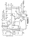
- Figure 4 is an electrical schematic of a power supply which includes a sensing circuit.
-
- A module for controlling the flow of power, particularly alternating current (AC) is described. In the following description numerous specific details are set forth, such as a specific power supply. It will be apparent to one skilled in the art that the present invention may be practiced without these details. In other instances, well-known circuits such as transceivers, have not been described in detail in order not to obscure the present invention.
- In Figure 1, the
module 10 is shown in an embodiment compatible with 110 volt, 60 cycle alternating current as used in the United States. The module is used betweenAC power lines 15 and aload 11. Theprongs 26 of a standard AC plug attached to themodule 10 are inserted into areceptacle 14. The receptacle receives power fromAC power lines 15. - The
load 11 is connected in series with afirst switch 12 associated with the load and these components are connected to aplug 13. Theplug 13 cooperatively engages areceptacle 25 of themodule 10. The first switch may be a manual switch, a switch indirectly controlled by another device such as a remote control, photocell, etc., or other switch in series with the load. - The module itself includes, in one embodiment, a
transceiver 20 which transmits and receives control signals, on to and from, thepower lines 15 and which provides and receives signals to and from thecontrol circuit 21. Thecontrol circuit 21 provides signals for controlling an electricallycontrollable switch 27. Switch 27, when closed, allows current to flow from thepower line 15 to theload 11, providedswitch 12 is closed. - Sensing
circuit 23 senses the position of thefirst switch 12 and provides signals representative ofswitch 12's state (i.e., opened or closed) to thecontrol circuit 21. In one embodiment there is leakage associated with the switch circuit which is used to aid in the sensing. - A
DC power supply 22 receives AC power from thelines 15 and provides DC power to thetransceiver 20,control circuit 21 and may provide power to thesensing circuit 23 where needed. Additionally, DC power may be used by the control circuit and/orswitch 27, as will be shown in connection with Figure 4, where theswitch 27 is a triac. - In operation, the
sensing circuit 23 senses the state of theswitch 12. When it senses that the state offirst switch 12 has changed, for instance, for a two position switch, that the switch has been closed, it provides a signal to thecontrol circuit 21 which in turn closesswitch 27 allowing current to flow through theload 11. Note that in the arrangement of Figure 1, the state of a first switch is being sensed and that switch is connected in series with the load. This allows, for instance, appliances, lamps and many other electrical devices used in both home and business having first switches to be connected into a network for remote sensing and control without any rewiring and without the need for additional first switches. - Looked at another way, the first switch which normally turns on and off a load such as a lamp, can be used more versatilely. For example, once the
switch 12 is closed and the lamp is on, thecontrol circuit 21 can be programmed to recognize the opening and closing ofswitch 12 occurring in some period of time; say two seconds. This opening and closing of theswitch 12 can be detected as a command and used by the control circuit to, for instance, dim the lamp. Or, the sequential (i.e., successive) opening and closing of the first switch can sequentially select varying levels of intensity. Thus an ordinary switch connected to an ordinary light bulb can cause the light bulb to have the functions of a three-way or n-way bulb. - Additionally, referring now to Figure 2, the first switch can be used to control other electrical items. In Figure 2, two
modules module 10 of Figure 1 are shown. Themodule 30 connects thepower lines 36 to alamp 33 through afirst switch 32. Themodule 31 connects thepower lines 36 to atelevision 35. When theswitch 32 is closed and thelamp 33 lights, the transceiver within themodule 30 can send a signal to the transceiver in themodule 31 causingmodule 31 to supply current to thetelevision 35 or other appliance. Thus, turning on and off thelamp 32 can activate a remotely located electrical device. Or for instance, themodule 30 can be programmed to send a signal to module 31 only whenlamp 33 is dimmed, thus thetelevision 35 is turned on only when thelamp 33 is dimmed. Alternatively, the activation of the TV can be sensed inmodule 31 and causelamp 33 to dim ifswitch 32 is closed. In another example, when theswitch 32 is closed, it could activate other modules so that other lamps are turned on. Similarly, when dimming occurs throughswitch 32, this could dim the lights associated with the other modules and also at the same time turn on thetelevision 35. Still alternatively, a control timer associated with one load can cause action in other modules. Numerous other possibilities and combinations can be achieved with the modules. - Figure 4 illustrates, in part, a prior art power supply for providing DC power (VA and VDD) to the
transceiver 20 andcell 21 and for the control lead of a triac. Additionally, the circuit of Figure 4 provides the sensing performed by thesensing circuit 23 of Figure 1. - The power supply is coupled between
lines Line 52 is coupled throughinductors capacitor 43 to adiode bridge 45. The diode bridge is also connected to theneutral line 60. The output of the diode bridge,line 46, is the positive potential (VA) andline 61 is the power supply common connection. The power supplycommon connection 61 is not fixed with respect to theneutral line 60 because of the fullwave diode bridge 45. - VA is regulated by the
zener diode 47. This diode is coupled in series withdiodes diodes diode 47 such that their temperature is approximately equal to the temperature of thediode 47. This provides temperature compensation for the potential VA. VA is also used to power alinear regulator 51. The output of thesupply 51, for the embodiment illustrated, is +5V on line 75 (VDD). The potential VA also powers transmit and receive circuitry of thetransceiver 20. - The
line 52 is coupled through themain terminals 58 of a triac toline 59. This line along withline 60 are coupled for example, to thefirst switch 12 and load 11 of Figure 1. The optically coupled triac (comprising 55 and 57) is controlled through thelight emitting diode 55 which receives current fromline 75 through theresistor 56. A low potential coupled overline 50 to thediode 55 causes the diode to conduct and provides light to trigger thecontrol triac 57 into conduction. Theresistor 72 andcapacitor 71 provide filtering to prevent unwanted noise triggering. When thetriac 57 conducts, current flows betweenline 52 andline 59 through the load and first switch. As is well-known, this conduction can occur over selected portions of the AC cycle thereby providing, for instance, dimming to a light bulb connected between thelines - The
transceiver 20 receives signals from thepower lines 52 through theinductor 41 andcapacitor 62, and transmits signals through thecapacitors inductor 41.Inductor 64 is coupled to the power supplycommon connection 61, and this common connection is coupled bycapacitors lines diode 67. The coupling of the receive and transmit signals to and from the power line is a known configuration used to facilitate the high frequency communication signals, substantially without interference from the 60Hz power signal. In one embodiment, thetransceiver 20 is a commercially available transceiver from Echelon Corporation specifically thePLT 21 power line transceiver. Additionally, the power supply discussed above and the coupling of the transceiver to the power lines is discussed in the "PLT 21 Power Line Transceiver User's Guide". - The
cell 21 may be a microprocessor or controller program to perform the functions described below or may be an intelligent cell known as a Neuron® chip. Such cells are available from Motorola, part no. MC143120B1DW. These cells can be programmed to perform the functions described in this application. - The state of a first switch connected to
line 59 is sensed online 70 through theresistor 74. This resistor couples theline 59 to one input terminal of thecell 21. As will be seen, the potential on this line is, in effect, compared with the potential (reference signal) connected to another input terminal ofcell 21 online 69.Line 69 is coupled toline 52 through theresistor 73. - Internal to the
cell 21,lines common connection 61 and VDD. This prevents the excursion of these reference signals from exceeding in the positive direction, VDD plus a diode drop, and in the negative direction the potential online 61 less a diode drop. The reference signal on line 69 (when clamped) is shown alongaxis 80 of Figure 3. As can be seen, the reference signal online 80 after clamping is approximately a square-wave with a period equal to the period of the 60Hz power frequency. - At first glance, it would appear that
line 59, when the triac is not conducting, is completely floating. However, this line is coupled to the power line throughresistor 72 andcapacitor 71. Consequently, the signal on line 70 (sense signal) has effectively three different steady states; one when the first switch is open, a second when the first switch is closed and the triac is conducting, and a third when the first switch is closed and the triac is off. These are shown on theaxes axis 82b is for triac conduction slightly less than 100% of the time. - As can be seen from the waveform of
axis 82a, the sense signal for the open first switch, substantially follows the reference signal onaxis 80. When the first switch is closed and the triac is not conducting, as seen onaxis 82c, there is a phase shift in the sense signal. Note the positive-to-negative transition of the sense signal is displaced from the positive-to-negative transition of the reference signal. Finally, for the case when the first switch is closed and the triac is conducting, as seen onaxis 82b, there is a period of time following positive-to-negative transitions of the reference signal that the sense signal remains positive. During theperiod 83, the signal is not well defined for purposes of detection. - Referring to Figure 3, if one examines the period after the reference signal transitions from positive-to-negative, it can be seen that the sense signal is high when the first switch is closed, and low when the first switch is open. During the first 1.5 milliseconds following positive-to-negative transitions of the reference signal,
cell 71 examines the state of the sense signal. If both are low, the first switch is determined to be open. (Compare the waveforms onaxes axis 80 with the waveforms onaxes - Thus, with the addition of two resistors (73 and 74) to the prior art power supply of Figure 4, sufficient information is obtained to permit a determination of the state (open or closed) of a first switch.
- The waveforms of Figure 3 were obtained using a 100 watt bulb as the load. Similar results can be achieved with other wattage bulbs.
- The sensing circuit of Figure 4 operates in part because of relative movement of the potential between
common connection 61 and theneutral line 60 resulting from the conduction of alternate dioded pairs ofbridge rectifier 45. If another power supply topology is used then other circuits can be used to sense the state of the first switch. Additionally, the sensing of the state of the first switch, in some cases, will be dependent upon the type of load (e.g., inductive load) which may cause shifts in waveforms and require examination of the sense signal at different periods of time or require a signal to be sensed from different points in the module. - The modules described above may also be used to report their status (e.g., first switch open/closed) to a central monitoring device that, for instance, displays the status information. Then, by way of example, one can monitor which lights or other appliances are on or off. Note if a load is absent (e.g., bulb burned out) this can also be displayed in some cases.
- Thus, a module has been described for interconnecting between AC power lines and a load which includes a first switch. The module is able to sense the state of the first switch and thereby control power to the load and to other loads connected to other modules.
Claims (5)
- A module (10) for interconnecting between an alternating current (AC) source (15) and an electrical load (11) having a first switch connected in series with the load, comprising:characterised by:an electrically controlled switching device coupled to control the flow of AC from the source through the load (11) and first switch (12);a control circuit (21) for controlling the switching device;a sensing circuit (23) coupled to the control circuit (21) for sensing states of the first switch (12) such that the state of the first switch is sensed and used to control the switching device; anda transceiver (20) coupled to the control circuit (21) and the AC source for transmitting signals representing the states of the first switch (12) and for receiving signals from other of the modules indicating the state of another first switch associated with the other of the modules for controlling the switching device based on the state of the other first switch.
- The module defined by claim 1 wherein the first switch (12) is a manual switch.
- The module defined by claim 1 wherein the first switch (12) and switching device are in a series with the load.
- The module defined by claims 2 or 3 wherein the switching device is a triac.
- The module defined by claim 4 wherein the control circuit (21) causes the triac to conduct for less than a full cycle of the AC when the state of the switch has changed state more than once.
Applications Claiming Priority (3)
| Application Number | Priority Date | Filing Date | Title |
|---|---|---|---|
| US08/840,342 US5942814A (en) | 1997-04-28 | 1997-04-28 | Module for controlling current to a load including sensing of the position of a switch |
| US840342 | 1997-04-28 | ||
| PCT/US1998/006843 WO1998049699A1 (en) | 1997-04-28 | 1998-04-06 | Module for controlling current to a load including sensing of the position of a switch |
Publications (3)
| Publication Number | Publication Date |
|---|---|
| EP0979523A1 EP0979523A1 (en) | 2000-02-16 |
| EP0979523A4 EP0979523A4 (en) | 2000-06-21 |
| EP0979523B1 true EP0979523B1 (en) | 2003-08-27 |
Family
ID=25282098
Family Applications (1)
| Application Number | Title | Priority Date | Filing Date |
|---|---|---|---|
| EP19980914549 Expired - Lifetime EP0979523B1 (en) | 1997-04-28 | 1998-04-06 | Module for controlling current to a load including sensing of the position of a switch |
Country Status (5)
| Country | Link |
|---|---|
| US (1) | US5942814A (en) |
| EP (1) | EP0979523B1 (en) |
| AU (1) | AU6887798A (en) |
| DE (1) | DE69817554T2 (en) |
| WO (1) | WO1998049699A1 (en) |
Families Citing this family (14)
| Publication number | Priority date | Publication date | Assignee | Title |
|---|---|---|---|---|
| US6554798B1 (en) | 1998-08-18 | 2003-04-29 | Medtronic Minimed, Inc. | External infusion device with remote programming, bolus estimator and/or vibration alarm capabilities |
| US6694209B1 (en) * | 2000-06-26 | 2004-02-17 | Echelon Corporation | Cell fabricated as an IC with a redesigned transceiver package which can be multiplexed to different states without user input |
| US6686831B2 (en) | 2001-01-23 | 2004-02-03 | Invensys Systems, Inc. | Variable power control for process control instruments |
| TW480507B (en) * | 2003-01-07 | 2002-03-21 | Taiwan Fuhbic Corp | Intelligent switch device and its wiring system |
| US6917167B2 (en) * | 2003-09-03 | 2005-07-12 | Lutron Electronics Co., Inc. | Method and apparatus for tracking sequences of an electrical device controllable from multiple locations |
| US7348742B2 (en) * | 2004-11-23 | 2008-03-25 | Energy Focus, Inc. | Lighting fixture with synchronizable optical filter wheel and related method |
| KR101158060B1 (en) * | 2005-07-01 | 2012-06-18 | 엘지전자 주식회사 | apparatus and method for controlling stand-by power in the washing machine |
| DE202006005559U1 (en) * | 2006-04-05 | 2007-08-16 | Zumtobel Lighting Gmbh | Connection device for home automation |
| WO2008035322A1 (en) * | 2006-09-18 | 2008-03-27 | Hinbit Development | A retrofitting power distribution device and uses thereof |
| US8175463B2 (en) * | 2008-09-24 | 2012-05-08 | Elbex Video Ltd. | Method and apparatus for connecting AC powered switches, current sensors and control devices via two way IR, fiber optic and light guide cables |
| US9494978B2 (en) * | 2013-06-13 | 2016-11-15 | Hanni B. Lozano | Power line docking station apparatus |
| CN104600964A (en) * | 2013-10-31 | 2015-05-06 | 通用电气公司 | Voltage adapter system used in device |
| US9356472B2 (en) * | 2014-09-02 | 2016-05-31 | e5 Global Innovations, Inc. | Systems and methods for remotely controlling a wall socket |
| RU2698708C2 (en) | 2014-10-28 | 2019-08-29 | Филипс Лайтинг Холдинг Б.В. | Apparatus, method and system for controlling load device through power line using power matching protocol |
Family Cites Families (6)
| Publication number | Priority date | Publication date | Assignee | Title |
|---|---|---|---|---|
| US4024528A (en) * | 1975-10-30 | 1977-05-17 | Boggs Luther M | Remote switching system |
| GB2083301B (en) * | 1980-09-01 | 1984-09-26 | South Eastern Elec Board | Method of and apparatus for controlling loads on an electrical power supply |
| US4418333A (en) * | 1981-06-08 | 1983-11-29 | Pittway Corporation | Appliance control system |
| US4782420A (en) * | 1987-06-05 | 1988-11-01 | Holdgaard Jensen Kurt | Safety switch apparatus |
| US4918690A (en) * | 1987-11-10 | 1990-04-17 | Echelon Systems Corp. | Network and intelligent cell for providing sensing, bidirectional communications and control |
| US5471190A (en) * | 1989-07-20 | 1995-11-28 | Timothy D. Schoechle | Method and apparatus for resource allocation in a communication network system |
-
1997
- 1997-04-28 US US08/840,342 patent/US5942814A/en not_active Expired - Lifetime
-
1998
- 1998-04-06 DE DE1998617554 patent/DE69817554T2/en not_active Expired - Fee Related
- 1998-04-06 AU AU68877/98A patent/AU6887798A/en not_active Abandoned
- 1998-04-06 EP EP19980914549 patent/EP0979523B1/en not_active Expired - Lifetime
- 1998-04-06 WO PCT/US1998/006843 patent/WO1998049699A1/en active IP Right Grant
Also Published As
| Publication number | Publication date |
|---|---|
| WO1998049699A1 (en) | 1998-11-05 |
| EP0979523A4 (en) | 2000-06-21 |
| AU6887798A (en) | 1998-11-24 |
| DE69817554T2 (en) | 2004-06-09 |
| DE69817554D1 (en) | 2003-10-02 |
| US5942814A (en) | 1999-08-24 |
| EP0979523A1 (en) | 2000-02-16 |
Similar Documents
| Publication | Publication Date | Title |
|---|---|---|
| EP0979523B1 (en) | Module for controlling current to a load including sensing of the position of a switch | |
| US6069457A (en) | Method and apparatus for controlling lights and other devices | |
| US6043635A (en) | Switched leg power supply | |
| EP2177090B1 (en) | Load control device having a gate current sensing circuit | |
| AU2006255105C1 (en) | Dimmer switch for use with lighting circuits having three-way switches | |
| US7683504B2 (en) | Multiple location electronic timer system | |
| US20090256483A1 (en) | Load Control Device Having a Visual Indication of an Energy Savings Mode | |
| CN101176129A (en) | Status indicator circuit for a dimmer switch | |
| US8952575B2 (en) | Three-way and four-way switching circuit | |
| US20060290210A1 (en) | Configurable power control system | |
| US9287708B2 (en) | Actuator and energy management system comprising such actuators | |
| CN207947922U (en) | Intelligent lighting system | |
| US5670846A (en) | Full power light control | |
| US5907198A (en) | Trickle power supply | |
| US5742105A (en) | Trickle power supply | |
| CN213342781U (en) | Single-fire circuit system | |
| EP0822645A2 (en) | Trickle power supply | |
| US20220141940A1 (en) | Garden lighting control system and method | |
| EP3468307A1 (en) | Two-wire load control system extension | |
| CN112188710A (en) | Single-fire circuit system | |
| CN2440289Y (en) | General infrared telecontrolled light-regulation switch | |
| CN2884692Y (en) | Two-line remote controlled switch | |
| JPS61163415A (en) | Load controller |
Legal Events
| Date | Code | Title | Description |
|---|---|---|---|
| PUAI | Public reference made under article 153(3) epc to a published international application that has entered the european phase |
Free format text: ORIGINAL CODE: 0009012 |
|
| 17P | Request for examination filed |
Effective date: 19991122 |
|
| AK | Designated contracting states |
Kind code of ref document: A1 Designated state(s): DE FR GB IT |
|
| A4 | Supplementary search report drawn up and despatched |
Effective date: 20000510 |
|
| AK | Designated contracting states |
Kind code of ref document: A4 Designated state(s): DE FR GB IT |
|
| RIC1 | Information provided on ipc code assigned before grant |
Free format text: 7H 01H 3/00 A, 7H 04M 11/04 B, 7H 02J 13/00 B |
|
| 17Q | First examination report despatched |
Effective date: 20020930 |
|
| GRAH | Despatch of communication of intention to grant a patent |
Free format text: ORIGINAL CODE: EPIDOS IGRA |
|
| GRAS | Grant fee paid |
Free format text: ORIGINAL CODE: EPIDOSNIGR3 |
|
| GRAA | (expected) grant |
Free format text: ORIGINAL CODE: 0009210 |
|
| AK | Designated contracting states |
Designated state(s): DE FR GB IT |
|
| PG25 | Lapsed in a contracting state [announced via postgrant information from national office to epo] |
Ref country code: FR Free format text: LAPSE BECAUSE OF FAILURE TO SUBMIT A TRANSLATION OF THE DESCRIPTION OR TO PAY THE FEE WITHIN THE PRESCRIBED TIME-LIMIT Effective date: 20030827 |
|
| REG | Reference to a national code |
Ref country code: GB Ref legal event code: FG4D |
|
| REF | Corresponds to: |
Ref document number: 69817554 Country of ref document: DE Date of ref document: 20031002 Kind code of ref document: P |
|
| PGFP | Annual fee paid to national office [announced via postgrant information from national office to epo] |
Ref country code: FR Payment date: 20040420 Year of fee payment: 7 |
|
| PLBE | No opposition filed within time limit |
Free format text: ORIGINAL CODE: 0009261 |
|
| STAA | Information on the status of an ep patent application or granted ep patent |
Free format text: STATUS: NO OPPOSITION FILED WITHIN TIME LIMIT |
|
| 26N | No opposition filed |
Effective date: 20040528 |
|
| EN | Fr: translation not filed | ||
| REG | Reference to a national code |
Ref country code: HK Ref legal event code: WD Ref document number: 1025423 Country of ref document: HK |
|
| PGFP | Annual fee paid to national office [announced via postgrant information from national office to epo] |
Ref country code: IT Payment date: 20090428 Year of fee payment: 12 Ref country code: DE Payment date: 20090429 Year of fee payment: 12 |
|
| PGFP | Annual fee paid to national office [announced via postgrant information from national office to epo] |
Ref country code: GB Payment date: 20090429 Year of fee payment: 12 |
|
| GBPC | Gb: european patent ceased through non-payment of renewal fee |
Effective date: 20100406 |
|
| PG25 | Lapsed in a contracting state [announced via postgrant information from national office to epo] |
Ref country code: DE Free format text: LAPSE BECAUSE OF NON-PAYMENT OF DUE FEES Effective date: 20101103 |
|
| PG25 | Lapsed in a contracting state [announced via postgrant information from national office to epo] |
Ref country code: IT Free format text: LAPSE BECAUSE OF NON-PAYMENT OF DUE FEES Effective date: 20100406 Ref country code: GB Free format text: LAPSE BECAUSE OF NON-PAYMENT OF DUE FEES Effective date: 20100406 |