EP0979516B1 - Cable - Google Patents
Cable Download PDFInfo
- Publication number
- EP0979516B1 EP0979516B1 EP99938011A EP99938011A EP0979516B1 EP 0979516 B1 EP0979516 B1 EP 0979516B1 EP 99938011 A EP99938011 A EP 99938011A EP 99938011 A EP99938011 A EP 99938011A EP 0979516 B1 EP0979516 B1 EP 0979516B1
- Authority
- EP
- European Patent Office
- Prior art keywords
- cable
- matrix
- elements
- core
- conducting elements
- Prior art date
- Legal status (The legal status is an assumption and is not a legal conclusion. Google has not performed a legal analysis and makes no representation as to the accuracy of the status listed.)
- Expired - Lifetime
Links
- 239000011159 matrix material Substances 0.000 claims abstract description 48
- 239000000463 material Substances 0.000 claims description 56
- 239000004020 conductor Substances 0.000 claims description 31
- 238000000034 method Methods 0.000 claims description 31
- 229920002635 polyurethane Polymers 0.000 claims description 19
- 239000004814 polyurethane Substances 0.000 claims description 19
- 229920000295 expanded polytetrafluoroethylene Polymers 0.000 claims description 12
- 230000003014 reinforcing effect Effects 0.000 claims description 12
- 239000012530 fluid Substances 0.000 claims description 8
- 238000001125 extrusion Methods 0.000 claims description 6
- 239000011230 binding agent Substances 0.000 claims description 5
- 150000001875 compounds Chemical class 0.000 claims description 5
- 229920000728 polyester Polymers 0.000 claims description 5
- -1 polyethylenes Polymers 0.000 claims description 5
- 230000005540 biological transmission Effects 0.000 claims description 4
- 239000004698 Polyethylene Substances 0.000 claims description 3
- 239000004743 Polypropylene Substances 0.000 claims description 3
- 229920000573 polyethylene Polymers 0.000 claims description 3
- 229920001155 polypropylene Polymers 0.000 claims description 3
- 229920001343 polytetrafluoroethylene Polymers 0.000 claims description 3
- 239000004810 polytetrafluoroethylene Substances 0.000 claims description 3
- NBVXSUQYWXRMNV-UHFFFAOYSA-N fluoromethane Chemical compound FC NBVXSUQYWXRMNV-UHFFFAOYSA-N 0.000 claims description 2
- 238000010438 heat treatment Methods 0.000 claims description 2
- 239000013307 optical fiber Substances 0.000 claims description 2
- 235000012222 talc Nutrition 0.000 claims 1
- 239000011162 core material Substances 0.000 description 46
- XEEYBQQBJWHFJM-UHFFFAOYSA-N Iron Chemical compound [Fe] XEEYBQQBJWHFJM-UHFFFAOYSA-N 0.000 description 10
- 239000004760 aramid Substances 0.000 description 9
- 229920003235 aromatic polyamide Polymers 0.000 description 9
- 230000003287 optical effect Effects 0.000 description 7
- 230000008569 process Effects 0.000 description 6
- 229910052742 iron Inorganic materials 0.000 description 5
- 238000005520 cutting process Methods 0.000 description 4
- 239000000835 fiber Substances 0.000 description 4
- XLYOFNOQVPJJNP-UHFFFAOYSA-N water Substances O XLYOFNOQVPJJNP-UHFFFAOYSA-N 0.000 description 4
- 238000005299 abrasion Methods 0.000 description 3
- 230000015572 biosynthetic process Effects 0.000 description 3
- 230000006835 compression Effects 0.000 description 3
- 238000007906 compression Methods 0.000 description 3
- 238000010276 construction Methods 0.000 description 3
- 238000006073 displacement reaction Methods 0.000 description 3
- 229920001971 elastomer Polymers 0.000 description 3
- 239000000806 elastomer Substances 0.000 description 3
- 238000005755 formation reaction Methods 0.000 description 3
- 239000007789 gas Substances 0.000 description 3
- 239000012943 hotmelt Substances 0.000 description 3
- 230000007246 mechanism Effects 0.000 description 3
- 230000002787 reinforcement Effects 0.000 description 3
- 230000000717 retained effect Effects 0.000 description 3
- 229910000679 solder Inorganic materials 0.000 description 3
- 239000004812 Fluorinated ethylene propylene Substances 0.000 description 2
- 239000004831 Hot glue Substances 0.000 description 2
- 229920000271 Kevlar® Polymers 0.000 description 2
- 239000000853 adhesive Substances 0.000 description 2
- 230000001070 adhesive effect Effects 0.000 description 2
- 229920001577 copolymer Polymers 0.000 description 2
- 238000002955 isolation Methods 0.000 description 2
- 238000004519 manufacturing process Methods 0.000 description 2
- 239000003921 oil Substances 0.000 description 2
- 229920009441 perflouroethylene propylene Polymers 0.000 description 2
- 229920002725 thermoplastic elastomer Polymers 0.000 description 2
- 230000003313 weakening effect Effects 0.000 description 2
- 239000004215 Carbon black (E152) Substances 0.000 description 1
- RYGMFSIKBFXOCR-UHFFFAOYSA-N Copper Chemical compound [Cu] RYGMFSIKBFXOCR-UHFFFAOYSA-N 0.000 description 1
- 239000004677 Nylon Substances 0.000 description 1
- 239000004952 Polyamide Substances 0.000 description 1
- XUIMIQQOPSSXEZ-UHFFFAOYSA-N Silicon Chemical compound [Si] XUIMIQQOPSSXEZ-UHFFFAOYSA-N 0.000 description 1
- BQCADISMDOOEFD-UHFFFAOYSA-N Silver Chemical compound [Ag] BQCADISMDOOEFD-UHFFFAOYSA-N 0.000 description 1
- 239000006096 absorbing agent Substances 0.000 description 1
- 229910045601 alloy Inorganic materials 0.000 description 1
- 239000000956 alloy Substances 0.000 description 1
- WYTGDNHDOZPMIW-RCBQFDQVSA-N alstonine Natural products C1=CC2=C3C=CC=CC3=NC2=C2N1C[C@H]1[C@H](C)OC=C(C(=O)OC)[C@H]1C2 WYTGDNHDOZPMIW-RCBQFDQVSA-N 0.000 description 1
- 239000004411 aluminium Substances 0.000 description 1
- 229910052782 aluminium Inorganic materials 0.000 description 1
- XAGFODPZIPBFFR-UHFFFAOYSA-N aluminium Chemical compound [Al] XAGFODPZIPBFFR-UHFFFAOYSA-N 0.000 description 1
- 238000005452 bending Methods 0.000 description 1
- 238000009954 braiding Methods 0.000 description 1
- 230000008859 change Effects 0.000 description 1
- 238000004140 cleaning Methods 0.000 description 1
- 239000002131 composite material Substances 0.000 description 1
- 238000001816 cooling Methods 0.000 description 1
- 239000012809 cooling fluid Substances 0.000 description 1
- 229910052802 copper Inorganic materials 0.000 description 1
- 239000010949 copper Substances 0.000 description 1
- 238000009826 distribution Methods 0.000 description 1
- 230000009189 diving Effects 0.000 description 1
- 238000005553 drilling Methods 0.000 description 1
- 239000002657 fibrous material Substances 0.000 description 1
- 238000011010 flushing procedure Methods 0.000 description 1
- 230000004907 flux Effects 0.000 description 1
- 239000004519 grease Substances 0.000 description 1
- 229930195733 hydrocarbon Natural products 0.000 description 1
- 150000002430 hydrocarbons Chemical group 0.000 description 1
- 239000004761 kevlar Substances 0.000 description 1
- 230000000116 mitigating effect Effects 0.000 description 1
- 239000000203 mixture Substances 0.000 description 1
- 229920001778 nylon Polymers 0.000 description 1
- 235000019271 petrolatum Nutrition 0.000 description 1
- 229920002647 polyamide Polymers 0.000 description 1
- 229920000098 polyolefin Polymers 0.000 description 1
- 239000004800 polyvinyl chloride Substances 0.000 description 1
- 239000011148 porous material Substances 0.000 description 1
- 230000002028 premature Effects 0.000 description 1
- 230000001681 protective effect Effects 0.000 description 1
- 238000007789 sealing Methods 0.000 description 1
- 238000010008 shearing Methods 0.000 description 1
- 230000035939 shock Effects 0.000 description 1
- 229910052710 silicon Inorganic materials 0.000 description 1
- 239000010703 silicon Substances 0.000 description 1
- 239000002210 silicon-based material Substances 0.000 description 1
- 229910052709 silver Inorganic materials 0.000 description 1
- 239000004332 silver Substances 0.000 description 1
- 238000005476 soldering Methods 0.000 description 1
- 229910001220 stainless steel Inorganic materials 0.000 description 1
- 239000011345 viscous material Substances 0.000 description 1
- 238000011179 visual inspection Methods 0.000 description 1
Images



Classifications
-
- G—PHYSICS
- G02—OPTICS
- G02B—OPTICAL ELEMENTS, SYSTEMS OR APPARATUS
- G02B6/00—Light guides; Structural details of arrangements comprising light guides and other optical elements, e.g. couplings
- G02B6/44—Mechanical structures for providing tensile strength and external protection for fibres, e.g. optical transmission cables
- G02B6/4401—Optical cables
- G02B6/4415—Cables for special applications
- G02B6/4427—Pressure resistant cables, e.g. undersea cables
-
- G—PHYSICS
- G02—OPTICS
- G02B—OPTICAL ELEMENTS, SYSTEMS OR APPARATUS
- G02B6/00—Light guides; Structural details of arrangements comprising light guides and other optical elements, e.g. couplings
- G02B6/44—Mechanical structures for providing tensile strength and external protection for fibres, e.g. optical transmission cables
- G02B6/4401—Optical cables
- G02B6/4429—Means specially adapted for strengthening or protecting the cables
- G02B6/4434—Central member to take up tensile loads
-
- H—ELECTRICITY
- H01—ELECTRIC ELEMENTS
- H01B—CABLES; CONDUCTORS; INSULATORS; SELECTION OF MATERIALS FOR THEIR CONDUCTIVE, INSULATING OR DIELECTRIC PROPERTIES
- H01B11/00—Communication cables or conductors
- H01B11/02—Cables with twisted pairs or quads
- H01B11/12—Arrangements for exhibiting specific transmission characteristics
- H01B11/16—Cables, e.g. submarine cables, with coils or other devices incorporated during cable manufacture
-
- H—ELECTRICITY
- H01—ELECTRIC ELEMENTS
- H01B—CABLES; CONDUCTORS; INSULATORS; SELECTION OF MATERIALS FOR THEIR CONDUCTIVE, INSULATING OR DIELECTRIC PROPERTIES
- H01B7/00—Insulated conductors or cables characterised by their form
- H01B7/17—Protection against damage caused by external factors, e.g. sheaths or armouring
- H01B7/18—Protection against damage caused by wear, mechanical force or pressure; Sheaths; Armouring
- H01B7/182—Protection against damage caused by wear, mechanical force or pressure; Sheaths; Armouring comprising synthetic filaments
Definitions
- This invention relates to cable and to the manufacture of cable.
- the invention has particular application in cable which is likely to be subject to flexing, radial compression and tensile and shear stresses.
- Embodiments of the invention are suited for use as ocean bottom cable (OBC).
- OBC ocean bottom cable
- One method of surveying the geology of subsea strata involves laying long lengths (for example 50 - 60 km lengths) of sensing cable in a serpentine manner on the sea floor; the cable is generally know as ocean bottom cable (OBC).
- the cable will typically comprise a number of cable sections, for example a 57 km cable may comprise 150 cable sections each of 380 m length, each cable section carrying a number of sensors.
- Acoustic waves are created in the water above the cable, which waves are reflected at varying amplitudes and angles by the strata beneath the sea floor.
- the reflected waves are detected by the sensors and the resulting signal output is analysed to produce a seismograph of the subsurface geology of the area.
- This method of geological surveying is perhaps most commonly used in identifying subsea hydrocarbon-bearing formations with potential for oil or gas production.
- the OBC is laid on the sea floor using a vessel equipped with an arrangement for deploying and retrieving the cable, known as a "linear traction wrench" or “squirter".
- the squirter comprises a plurality of pairs of driven wheels, often shod with vehicle tyres, each pair defining a "nip” or "pinch point” for engaging a section of cable.
- the vessel will follow a serpentine path over the area of sea floor to be surveyed, with the squirter deploying the cable at a corresponding rate. Once the survey has been completed the squirter is operated to retrieve the cable.
- Conventional OBC comprises a central reinforcing fibre core, a plurality of elongate components, typically insulated conductors helically wound around the core, an extruded sheath, possible further braided fibre reinforcement, and an outer abrasion resistant protective sheath or jacket.
- a section of the OBC passes through the squirter or is subjected to flexing, compressive and longitudinal forces are quickly transferred to the components and may, in time, result in damage to the components.
- the components of the cable for example the reinforcing braid, may also shift position within the cable upon flexing. When the cable is next subjected to longitudinal stress, the displaced component may be subject to damage.
- the squirter must apply significant compressive and longitudinal forces to the cable. These forces are of course first applied to the exterior of the cable and are then transferred radially inward through the components of the cable to the central core. This may place significant stresses on individual components, increasing the possibility of component failure.
- One recognised failure mechanism is termed "Z-kinking", and involves a component being subject to longitudinal forces which stretch the component beyond its elastic limit or “yield point.” When the forces are removed, the elongated component retracts and is folded back on itself, thereby damaging the component. Furthermore, the different components of the cable may behave differently under stress.
- the overlying extruded sheath or jacket is likely to have greater elasticity than the adjacent layer of helically wound conductors, which may lead to the jacket extending longitudinally relative to the conductor layer.
- the longitudinally flexing jacket may damage underlying components.
- such displacement prevents the effective transfer of shear forces from the jacket to the reinforcing core. The sheath will then bear substantially all of the tension applied to the cable by the squirter, possibly leading to premature failure of the jacket and cable.
- the jacket's inner profile corresponds to the rope-like surface of the helically wound conductors, such that longitudinal displacement of the jacket relative to the conductor layer may impart considerable localized abrasions and loads upon the conductors.
- the longitudinal force applied to the cable jacket is typically distributed over longer sections of cable by adding squirter nips.
- the compressive forces applied at the squirter nips are typically increased, and elaborate controls are sometimes employed to avoid jerking.
- cables have been filled with oil or other viscous materials with a view to flushing out any trapped air and filling any voids in the cable.
- Such methods generally have other problems associated with them and are only partially effective. Complete air removal is difficult to achieve, particularly with higher viscosity materials, and lower viscosity fluids require special considerations for filling the cable and may reduce load transfers.
- EP-A-0 193 780 discloses a submarine cable for optical fibre telecommunications.
- the cable has a core comprising armouring of antitorsional rope and a plurality of small tubes wound helically and in direct contact with the armouring.
- the small tubes loosely house the optical fibres and are filled with a practically incompressible fluid such as a petroleum jelly or a silicon grease.
- US-A-4,196,307 relates to a unitised marine umbilical cable carrying any number or combination of conventional elements such as hoses and electrical cables.
- a centre stress member disposed along the axis of the marine umbilical cable is capable of supporting an underwater device such as a diving bell should the primary down line break.
- Cylindrically surrounding the stress member is a compression extrusion of a high strength highly resilient elastomer around which are helically cabled various conventional elements.
- a resilient fill material Within the interstices between the high strength elastomer and the helically cabled elements.
- the resilient fill material and high strength highly resilient, low durometer elastomer serve as a radial shock absorber against tensional impact upon the umbilical or radial forces thereupon.
- a cable comprising: a stress-bearing matrix extending substantially through the length of the cable; and a plurality of conducting elements extending substantially through the length of the cable, said plurality of conducting elements being located within and spaced from one another by said stress-bearing matrix, wherein at least one of the plurality of conducting elements is in intimate contact with a low friction liner disposed about the at least one of the plurality of conducting elements and at least one of the conducting elements is longitudinally moveable relative to the stress-bearing matrix.
- the provision of the low friction liner disposed about at least one of the conducting elements allows embodiments of the present invention to be designed such that loads are transferred to selected conducting elements at differing rates. This is particularly useful where the elements are fragile or susceptible to stress induced damage, for example, optical fibres or small diameter electrical conductors. Further the flexibility of the cable is improved as relatively inelastic elements, such as metallic conductors, may incur minimal loads over short lengths as the cable flexes.
- the intimate contact between the conducting element and the liner of the present invention provides the cable with structural stability, that is the conducting element will not move laterally within the liner as the cable experiences stresses and strains; as noted above, displacing individual elements within a cable may change the electrical, optical, and/or mechanical characteristics of the elements or cable in general.
- the elements and liners of the present invention are more compact, and thus a cable of a given diameter may accommodate a greater number of elements.
- locating a liner around an element in accordance with the present invention is likely to be easier, more reliable and thus less expensive than locating an element in a tube and completely filling the tube with a viscous incompressible fluid.
- a cable comprising a plurality of elongate conducting elements located within and spaced from one another by a stress-bearing matrix substantially throughout the length of the cable, the cable being non-rigid and bendable in multiple planes.
- the cable is round.
- the elements are helically wound, and most preferably the elements are wound around a central axis of the cable.
- the low friction liner may be formed of a friction-reducing material, such as expanded polytetrafluoroethylene (ePTFE), to facilitate sliding movement of the element.
- ePTFE expanded polytetrafluoroethylene
- Other materials which may be used include ethylene-propylene copolymer (EPC), polyester, polyethylene, and fluorocarbon or silicon based materials.
- the matrix fills substantially all of the space between the elements, and is preferably substantially incompressible. This is useful in applications in which the cable experiences high external pressures, for example where the cable serves as ocean bottom cable (OBC). This feature is also useful in minimising the risk of damage or deformation of the cable on passing through a cable squirter or other arrangement defining a nip.
- OBC ocean bottom cable
- the elements may include one or more electrical conductors, one or more optical fibres, one or more force transmission members, and ⁇ or one or more fluid transmission conduits for conducting, for example, pressurised gases, hydraulic fluids, exhaust gases or cooling fluids.
- the electrical conductors may be of copper, silver, or aluminium or alloys containing these materials.
- the electrical conductors may be insulated by any suitable material, such as ePTFE, ethylene-propylene copolymer (EPC), polyester-based materials such as MIL-ENE ® obtainable from W L Gore & Associates, fluorinated ethylene-propylene copolymer (FEP), or polyvinylchloride (PVC).
- ePTFE ethylene-propylene copolymer
- EPC ethylene-propylene copolymer
- polyester-based materials such as MIL-ENE ® obtainable from W L Gore & Associates, fluorinated ethylene-propylene copolymer (FEP), or polyvinylchloride (PVC).
- Each conducting element may comprise a single member, or may comprise a plurality of members, for example a liner may accommodate a quad, that is the conducting element may comprise two pairs of electrical conductors.
- the cable includes load-bearing reinforcing elements.
- the cable will include a central load-bearing core, and may be provided with an outer sheathing of load-bearing elements.
- the load-bearing core and sheathing elements may be a synthetic or natural strength member and may comprise a fibrous material.
- the load-bearing core and sheathing elements may be of: aramid fibre, for example KEVLAR ® fibre material available from DuPont; stainless steel wire; polyamide fibres, such as nylon fibres; or ePTFE fibres such as RASTEX ® fibres obtainable from W L Gore & Associates in Putzbrunn, Germany. These elements may be impregnated with materials which are bondable to the matrix material.
- a method of forming a cable comprising:
- the elongate elements are laid into the outer surface of the core before the core has set, such that the core surface deforms to accommodate the elements.
- the matrix forming material may then be applied to fill any remaining spaces between the elements.
- the core surface may be subject to heating to prevent the material from setting prior to application of the elements.
- the method of handling the core will be selected for compatibility with the matrix-forming material setting mechanism.
- At least some of the elongate elements are provided with sheaths of matrix-forming material which merge with the other elements of matrix-forming material during processing. This method facilitates accurate placement of the elongate elements within the matrix, particularly when the sum of the diameters of the sheathed elongate elements is equivalent to the circumference of the cable at the centres of the elongate elements.
- a single stage extrusion process is utilised to form the matrix in a single step. This may be achieved by utilising a multi-holed extruder tip and profiled die placed at the gathering point of a non-planetary cabler with a rotating take-up.
- the matrix is formed using a material which sets by means of a mechanism other than cooling, such as a two-part compound or a heat or UV-curable material.
- the matrix-forming material is polyurethane, though of course any suitable material may be utilised, including thermoplastic rubber (TPR), polyester (PES); or polyolefins including polyethylene or polypropylene (PP).
- TPR thermoplastic rubber
- PET polyester
- PP polyolefins including polyethylene or polypropylene
- the core-forming material and sheath-forming materials are the same or similar and will bond to one another.
- the modulus of the matrix-forming material may be selected to suit particular applications: a low modulus material would result in a more flexible cable but might not be suitable for use in cable experiencing high pressures and would not be well adapted to transfer load, whereas a higher modulus material would be less flexible but better adapted to withstand pressure and loads.
- One or both of the core and the sheath may be extruded.
- the matrix-forming material core is formed around a central load-bearing core.
- the provision of the stress-bearing matrix around the core allows forces applied externally to the cable, for example by a cable squirter, to be more evenly distributed around and effectively transferred to the load-bearing core.
- any forces applied or transferred to the elements result in the elements tending to move individually relative to the matrix, rather than as a single composite unit as in conventional cables.
- This has significant advantages where "takeouts" are provided in a cable, that is when an element, or a portion of an element, sometimes known as a "pig-tail", is pulled out of the cable for connection to a device, sensor and the like mounted on the cable.
- the tendency for the conductor layer to move longitudinally as a unit relative to overlying sheaths increases the risk of the pig-tail being sheared due to movement between the elements and the overlying sheaths.
- the tendency for such movement is substantially reduced, and as elements will tend to move individually within the cable any movement will follow the helical path of the respective element, substantially reducing the risk of shearing.
- the window which is cut in the cable sheath to form the take out may be relatively small in cables according to embodiments of the present invention, as described below.
- the window which is cut in the outer sheath or jacket is generally of the same dimensions as the pig-tail, thus a 7.5 cm pig-tail will result in a 7.5 cm window being cut in the cable sheath or jacket.
- This will result in the outer reinforcing fibres, typically KEVLAR braid, being cut through at a number of points, weakening the cable.
- the provision of elements isolated and spaced apart by the matrix, and also the use of transparent sheathing allows an operator to form a pig-tail by cutting or drilling two relatively small holes to intersect the selected element, cutting the element at one hole and then pulling the cut tail of the element through the other hole. It will normally be possible to cut the holes without damaging the outer reinforcing fibres and weakening the cables, and to pull the element from the matrix without sustaining damage.
- a combination of a cable and a device comprising: a cable with an outer surface and having a stress-bearing matrix extending substantially through the length of the cable, a plurality of conducting elements each extending in a path substantially through the length of the cable and being located within and spaced from one another by said stress-bearing matrix, at least one hole being cut from the outer surface of the cable to a point within said stress-bearing matrix and intersecting the path of at least one of the plurality of conducting elements; wherein at least one of the plurality of conducting elements extends through said at least one hole and is connected to the device.
- a take out in a cable comprising at least one elongate element extending along a path through the body of the cable and contained within a sheath, the method comprising:
- the element is movable relative to the body of the cable and is most preferably provided within a low-friction liner.
- the overlying matrix material is selected to be transparent, such that the location of the element and any sensitive overlying elements (for example reinforcing fibres, adjacent elements and the like) within the body of the cable may be ascertained by visual inspection.
- any sensitive overlying elements for example reinforcing fibres, adjacent elements and the like
- the cable 8 comprises an outer sheath or jacket 10, a continuous load-bearing polyurethane matrix 12 extending throughout the length of the cable and within which are set: a load-bearing central aramid fibre core 14; a plurality of helically wound elongate elements in the form of insulated conductors 16; and outer aramid fibre reinforcement in the form of a braid 18.
- the insulated conductors 16 and the core 14 are separated by the matrix 12, with the matrix extending between the insulated conductors 16.
- the insulated conductors 16 are contained within liners 17 and are movable relative to the liners 17.
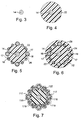
- Steps in forming at least the inner portion of the cable 10 are illustrated in Figures 3 through 6 of the drawings.
- the load-bearing fibrous core 14 ( Figure 3) is passed through an extrusion die and a core 22 of matrix-forming material 25 extruded over the fibrous core 14 ( Figure 4).
- the core 22 is retained at an elevated temperature by appropriate heaters.
- the heated core 22 is then passed through a cabling station, where the insulated conductors 16, in their liners 17, are pressed into the hot outer surface of the core 22.
- the outer surface of the core 22 deforms to accommodate the insulated conductors 16 to form core 26 ( Figure 5).
- the core 26 is then passed through a further extrusion die, where a sheath of matrix-forming material 24 is extruded over the core 26, the material 24 moving into the spaces between the insulated conductors 16 to bond with the core material 22.
- the core material 22 and sheath material 24 are then permitted to set, in the process bonding to form the homogeneous matrix 12 and a core 28 ( Figure 6).
- Other layers of material, such as the outer fibre reinforcement 18 and ⁇ or overlying jackets 10 may subsequently be applied over the core 28.
- the outer jackets 10 and the materials 24 and 25 which make up matrix 12 are of the same or similar materials which are bondable with one another, preferably polyurethane.
- FIG. 7 of the drawings illustrates a step in an alternative, and preferred, method of forming the inner portion of a cable in accordance with the present invention.
- the heated core 122 is passed through a cabling station, where heated conductors 116, provided with ePTFE liners 117 and thicker polyurethane sleeves 119, are pressed into the soft outer surface of the core 122.
- a sheath of matrix-forming material is subsequently extruded over the sheathed conductors 116.
- the method is preferred as it facilitates location of the conductors 116 around the core 122: the sum of the diameters of the sheathed conductors 116 is approximately equivalent to the desired circumference of the cable at the centres of the conductors.
- a single stage extrusion may be utilised, to form the matrix 12 in a single step. This may be achieved by utilising a multi-holed tip and profiled die placed at the gathering point of a non-planetary cabler with a rotating take-up.
- the matrix is formed of a two-part polyurethane compound.
- the compound may be injected onto polyurethane-sheathed components at a cross-head located at the gathering point of a cabler. If required, a polyurethane binder may then be bound around the cable to hold the matrix-forming material in place while the polyurethane compound sets.
- the cable 208 comprises an outer jacket 210, a stress-bearing polyurethane matrix 212 extending through the length of the cable and within which are retained: a load-bearing central aramid fibre core or strength member 214; a plurality of conducting elements in the form of power and sensor quads 216 (that is each element contains two pairs of conductors); and outer braided aramid strength members 218.
- the quads 216 are contained within close-fitting low friction ePTFE liners 217 such that the quads 216 are longitudinally movable relative to the matrix 212.
- the Figures illustrate steps in the formation of the cable 208, Figure 8 showing the cable construction after a star-shaped core 222 of polyurethane has been extruded onto the central strength member 214, and the quads 216 laid in the grooves 223 defined in the surface of the core 222.
- the grooves 223 may extend helically to facilitate bending of the cable, or may extend axially.
- a inner "jacket" 224 of polyurethane material is then pressure extruded over the core 222 and quads 216 to fill the grooves, as illustrated in Figure 9, the core 222 and jacket 224 setting and bonding to form the substantially homogeneous matrix 212.
- the braiding 218 is then applied and the outer jacket 210 extruded onto the matrix 212, the finished cable being illustrated in Figure 10.
- This embodiment provides improved component isolation, and the location of the components in the matrix 212 provides excellent load transfer from the outer jacket 210 to the central strength member 214.
- FIG. 11 of the drawings is a diagrammatic longitudinal sectional view of a combination of a cable and a sensor in accordance with an embodiment of another aspect of the present invention.
- the cable 308 is of similar construction to the cables described above, comprising a transparent polyurethane outer jacket 310, a stress-bearing polyurethane matrix 312, a central strength member 314, a plurality of helically wound quads 316, and outer reinforcing aramid braid 318.
- the quads 316 are contained within close-fitting low friction ePTFE liners 317 such that the quads 316 are longitudinally movable relative to the matrix 312.
- One of the quads 316 is shown extending through the jacket 310 and braid 318 to connect to a device, in the form of a sensor 350, mounted on the cable 308.
- the illustrated arrangement is utilised for mounting sensors on OBC and the method of forming the "take out” to allow the formation of a connection between the cable 308 and the sensor 350 is described below.
- the quads 316 are visible within the cable 308, allowing an operator to visually locate a required quad 316; in the region where the sensor 350 is to be located on the cable 308, the operator then identifies a point along the length of the required quad 316 where the overlying aramid braid 318 does not obstruct access to the quad 316.
- a hot (around 250°C) iron with a blunt tip the operator then bores through the jacket 310 down to the quad 316, taking care not to damage or expose any of the braid 318.
- the exposed quad 316 is then hooked with a tool, care being taken not to nick neighbouring components.
- the quad 316 is then pulled through the hole 352 formed in the jacket 310 and cut with suitable pair of cutters, ensuring that all components of the quad 316 are cut, including, in this example, an aramid strength member and the low friction ePTFE binder 317.
- the operator then visually locates a point along the quad 316 approximately 10 cm (four inches) from the cut point in the direction of the cable end connector in which the overlying braid 318 does not obstruct access to the quad 316.
- the operator then burns a trough 354 in the jacket 310 parallel and above the quad 316 down to just above the aramid braid 318, and then, with the blunt tip of the iron, bores through the outer jacket 310 down to the quad 316. Any excess polyurethane is trimmed away, and the trough 354 tapered into the hole 356, again care being taken not to damage or expose any of the braid 318.
- the loose end or tail of the quad 316 is then slowly pulled through the hole 356. If the ePTFE binder 317 is damaged, the base of the exposed tail is taped with PTFE pipe tape. A short PTFE tube 358 is then slid over the quad 316 and inserted into the hole 356. The polyurethane in the area around the base of the tube 358 is then heated with the side of the hot iron and polyurethane-based adhesive applied with a hot melt gun. The free end of the tube 358 is then laid in the trough 354 and adhesive applied from the hot melt gun over the top and sides of the tube 358 to secure the tube 358 to the cable 308. The hot iron and hot melt gun are then utilised to patch the quad cut hole 352.
- the quad 316 is then terminated as described below (but which level of detail is not shown in the Figure).
- the quad strength member is tied to an anchor and the anchor attached to the cable with hot melt adhesive such that the strength member exits directly out of the tube 358.
- a service loop is then constructed, by threading approximately 5 cm (two inches) of the quad 316 into the tube 358 such that it forms an S-bend inside the tube 358, and sealing the end of the tube 358 with hot melt adhesive.
- the quad is then terminated, by slipping a boot seal over each of the individual quad wires and, with a connector locking ring in place, soldering each wire into an appropriate solder cup. Once the solder joints have been cleaned of flux, the boot seals are slid down over the solder cups.
- a mould is placed around the takeout and natural polyurethane 360 injected into the mould. On the polyurethane setting, the mould is removed and any excess polyurethane flash removed. The sensor 350 may then be connected to the quad 316 and secured to the cable 308.
- the cables of the present invention permit a takeout to be formed by only removing or forming two small holes on the cable jacket, and without damaging the reinforcing braid. Further, in the present invention, the holes may be resealed, unlike takeouts in existing cables in which a large cutout must be retained to accommodate the relative movement which occurs between the individual conductors and the outer cable jacket.
- composition of the cables described above offer numerous advantages over the prior art cables, including: enhanced ability to transfer longitudinal or shear forces radially through the cable to the load bearing elements; increased resistance to radial compression, whether resulting from fluid pressure or mechanical pressure; absence of contact and abrasion between the elements; and greater isolation of the conductors from forces applied to the cable, thereby retaining flexibility throughout the cable.
- problems associated with the movement of component layers relative to overlying layers such as those encountered in the construction of takeouts and as specifically discussed above, are obviated.
- the cable also remains flexible and bendable in multiple planes, facilitating handling and increasing the number of dynamic applications in which the cable may be utilised.
- the matrix will not tend to deform to any great extent when subject to stress, particularly under longitudinal or shear stresses.
- the matrix may transfer forces applied to the exterior of the cables by a squirter to the load-bearing core without substantial deformation, mitigating disruption to the internal cable configuration and damage to the conductors.
- the elongate elements may include optical fibres, force transmission cables or fluid conduits and the liners may be omitted or modified such that there is a predetermined transfer of forces from the matrix to selected elongate elements, which may be useful in reinforcing the cable.
Landscapes
- Physics & Mathematics (AREA)
- General Physics & Mathematics (AREA)
- Optics & Photonics (AREA)
- Insulated Conductors (AREA)
- Flexible Shafts (AREA)
- Control Of Motors That Do Not Use Commutators (AREA)
- Laying Of Electric Cables Or Lines Outside (AREA)
- Electric Cable Arrangement Between Relatively Moving Parts (AREA)
- Organic Insulating Materials (AREA)
- Cable Transmission Systems, Equalization Of Radio And Reduction Of Echo (AREA)
Abstract
Description
- This invention relates to cable and to the manufacture of cable. The invention has particular application in cable which is likely to be subject to flexing, radial compression and tensile and shear stresses. Embodiments of the invention are suited for use as ocean bottom cable (OBC).
- One method of surveying the geology of subsea strata involves laying long lengths (for example 50 - 60 km lengths) of sensing cable in a serpentine manner on the sea floor; the cable is generally know as ocean bottom cable (OBC). The cable will typically comprise a number of cable sections, for example a 57 km cable may comprise 150 cable sections each of 380 m length, each cable section carrying a number of sensors. Acoustic waves are created in the water above the cable, which waves are reflected at varying amplitudes and angles by the strata beneath the sea floor. The reflected waves are detected by the sensors and the resulting signal output is analysed to produce a seismograph of the subsurface geology of the area. This method of geological surveying is perhaps most commonly used in identifying subsea hydrocarbon-bearing formations with potential for oil or gas production.
- The OBC is laid on the sea floor using a vessel equipped with an arrangement for deploying and retrieving the cable, known as a "linear traction wrench" or "squirter". Typically, the squirter comprises a plurality of pairs of driven wheels, often shod with vehicle tyres, each pair defining a "nip" or "pinch point" for engaging a section of cable. The vessel will follow a serpentine path over the area of sea floor to be surveyed, with the squirter deploying the cable at a corresponding rate. Once the survey has been completed the squirter is operated to retrieve the cable.
- Conventional OBC comprises a central reinforcing fibre core, a plurality of elongate components, typically insulated conductors helically wound around the core, an extruded sheath, possible further braided fibre reinforcement, and an outer abrasion resistant protective sheath or jacket. When a section of the OBC passes through the squirter or is subjected to flexing, compressive and longitudinal forces are quickly transferred to the components and may, in time, result in damage to the components. The components of the cable, for example the reinforcing braid, may also shift position within the cable upon flexing. When the cable is next subjected to longitudinal stress, the displaced component may be subject to damage.
- As the cable is deployed and retrieved, particularly in deep water, the weight and drag on the cable suspended from the squirter is considerable. Accordingly, the squirter must apply significant compressive and longitudinal forces to the cable. These forces are of course first applied to the exterior of the cable and are then transferred radially inward through the components of the cable to the central core. This may place significant stresses on individual components, increasing the possibility of component failure. One recognised failure mechanism is termed "Z-kinking", and involves a component being subject to longitudinal forces which stretch the component beyond its elastic limit or "yield point." When the forces are removed, the elongated component retracts and is folded back on itself, thereby damaging the component. Furthermore, the different components of the cable may behave differently under stress. For example, the overlying extruded sheath or jacket is likely to have greater elasticity than the adjacent layer of helically wound conductors, which may lead to the jacket extending longitudinally relative to the conductor layer. Where such extensions occur rapidly over short sections of cable, as at the squirter during sudden starts or stops or due to pitching and yawing of the vessel, the longitudinally flexing jacket may damage underlying components. Also, such displacement prevents the effective transfer of shear forces from the jacket to the reinforcing core. The sheath will then bear substantially all of the tension applied to the cable by the squirter, possibly leading to premature failure of the jacket and cable. Where the jacket has been pressure extruded over the conductor layer, the jacket's inner profile corresponds to the rope-like surface of the helically wound conductors, such that longitudinal displacement of the jacket relative to the conductor layer may impart considerable localized abrasions and loads upon the conductors. To avoid damage caused by inefficient load transfers as described above, the longitudinal force applied to the cable jacket is typically distributed over longer sections of cable by adding squirter nips. The compressive forces applied at the squirter nips are typically increased, and elaborate controls are sometimes employed to avoid jerking.
- In existing OBCs, it is common for voids to remain within the core of the cable. As a result, water pressure will often deform the cable as the atmospheric voids collapse and move within the cable, displacing individual elements within the cable and thus changing the electrical, optical, and\or mechanical characteristics of the elements or cable in general. Such displacements may increase rigidity in regions of the cable, for example, resulting in handling problems and increasing the likelihood of component damage when the cable is reprieved. Displaced air within the cable may also collect in pressurised pockets which breach the outer jacket on retrieval of the cable, allowing water to penetrate into the cable. To avoid problems associated with voids, cables have been filled with oil or other viscous materials with a view to flushing out any trapped air and filling any voids in the cable. Such methods, however, generally have other problems associated with them and are only partially effective. Complete air removal is difficult to achieve, particularly with higher viscosity materials, and lower viscosity fluids require special considerations for filling the cable and may reduce load transfers.
- EP-A-0 193 780 discloses a submarine cable for optical fibre telecommunications. The cable has a core comprising armouring of antitorsional rope and a plurality of small tubes wound helically and in direct contact with the armouring. The small tubes loosely house the optical fibres and are filled with a practically incompressible fluid such as a petroleum jelly or a silicon grease.
- US-A-4,196,307 relates to a unitised marine umbilical cable carrying any number or combination of conventional elements such as hoses and electrical cables. A centre stress member disposed along the axis of the marine umbilical cable is capable of supporting an underwater device such as a diving bell should the primary down line break. Cylindrically surrounding the stress member is a compression extrusion of a high strength highly resilient elastomer around which are helically cabled various conventional elements. Within the interstices between the high strength elastomer and the helically cabled elements is a resilient fill material. The resilient fill material and high strength highly resilient, low durometer elastomer serve as a radial shock absorber against tensional impact upon the umbilical or radial forces thereupon.
- It is among the objections of embodiments of the present invention to provide an OBC which obviates or mitigates these difficulties.
- It is a further objective of embodiments of the present invention to provide an improved cable containing a plurality of elements in which the elements are protected from stresses and forces applied to the cable.
- According to the present invention there is provided a cable comprising: a stress-bearing matrix extending substantially through the length of the cable; and a plurality of conducting elements extending substantially through the length of the cable, said plurality of conducting elements being located within and spaced from one another by said stress-bearing matrix, wherein at least one of the plurality of conducting elements is in intimate contact with a low friction liner disposed about the at least one of the plurality of conducting elements and at least one of the conducting elements is longitudinally moveable relative to the stress-bearing matrix.
- In use, the provision of the low friction liner disposed about at least one of the conducting elements allows embodiments of the present invention to be designed such that loads are transferred to selected conducting elements at differing rates. This is particularly useful where the elements are fragile or susceptible to stress induced damage, for example, optical fibres or small diameter electrical conductors. Further the flexibility of the cable is improved as relatively inelastic elements, such as metallic conductors, may incur minimal loads over short lengths as the cable flexes. In contrast to the cable configuration disclosed in EP-A-O 193 780, in which optical fibres are loosely housed in tubes, the intimate contact between the conducting element and the liner of the present invention provides the cable with structural stability, that is the conducting element will not move laterally within the liner as the cable experiences stresses and strains; as noted above, displacing individual elements within a cable may change the electrical, optical, and/or mechanical characteristics of the elements or cable in general. Further, the elements and liners of the present invention are more compact, and thus a cable of a given diameter may accommodate a greater number of elements. In addition, locating a liner around an element in accordance with the present invention is likely to be easier, more reliable and thus less expensive than locating an element in a tube and completely filling the tube with a viscous incompressible fluid.
- According to another aspect of the present invention there is provided a cable comprising a plurality of elongate conducting elements located within and spaced from one another by a stress-bearing matrix substantially throughout the length of the cable, the cable being non-rigid and bendable in multiple planes.
- In use, when a longitudinal stress is applied to cables of embodiments of these aspects of the invention via the jacket of the cable, for example by a squirter arrangement for deploying or retrieving cable, shear forces applied to the outer surface of the jacket are transferred radially inwardly through the cable primarily via the matrix. The presence of the matrix material between individual elements significantly reduces the amount of shear forces transferred radially inwardly of the cable via load-sensitive elements, and instead facilitates concentration of said forces on selected load bearing elements within the cable. In testing it has been found that longitudinal forces applied externally to cables in accordance with embodiments of the present invention will transfer to specified load bearing elements within the cable at a rate in excess of ten times that of longitudinal forces applied to a comparable conventional cable. Subsequently, lower longitudinal forces are transferred to selected sensitive elements and at a greatly reduced rate. In addition, the presence of the matrix material surrounding the individual elements allows for more even distributions of compressive forces. Where the cable is utilised as an ocean bottom cable (OBC), these features allow much higher loads to be applied over much shorter squirter lengths than those required for conventional ocean bottom cables.
- Preferably, the cable is round. Preferably also, the elements are helically wound, and most preferably the elements are wound around a central axis of the cable.
- Preferably also, a plurality of elements are located within respective low friction liners. The low friction liner may be formed of a friction-reducing material, such as expanded polytetrafluoroethylene (ePTFE), to facilitate sliding movement of the element. Other materials which may be used include ethylene-propylene copolymer (EPC), polyester, polyethylene, and fluorocarbon or silicon based materials. Utilising a porous material, such as ePTFE, to form the liner also allows the matrix-forming material to penetrate into the porous structure to secure the liner to the matrix thereby helping to maintain the structural integrity of the liner. The low friction liner material may be tape-wrapped around the element or may be in the form of an extruded tube.
- Preferably also, the matrix fills substantially all of the space between the elements, and is preferably substantially incompressible. This is useful in applications in which the cable experiences high external pressures, for example where the cable serves as ocean bottom cable (OBC). This feature is also useful in minimising the risk of damage or deformation of the cable on passing through a cable squirter or other arrangement defining a nip.
- The elements may include one or more electrical conductors, one or more optical fibres, one or more force transmission members, and\or one or more fluid transmission conduits for conducting, for example, pressurised gases, hydraulic fluids, exhaust gases or cooling fluids. The electrical conductors may be of copper, silver, or aluminium or alloys containing these materials.
- The electrical conductors may be insulated by any suitable material, such as ePTFE, ethylene-propylene copolymer (EPC), polyester-based materials such as MIL-ENE ® obtainable from W L Gore & Associates, fluorinated ethylene-propylene copolymer (FEP), or polyvinylchloride (PVC).
- Each conducting element may comprise a single member, or may comprise a plurality of members, for example a liner may accommodate a quad, that is the conducting element may comprise two pairs of electrical conductors.
- Preferably also, the cable includes load-bearing reinforcing elements. Typically, the cable will include a central load-bearing core, and may be provided with an outer sheathing of load-bearing elements. The load-bearing core and sheathing elements may be a synthetic or natural strength member and may comprise a fibrous material. The load-bearing core and sheathing elements may be of: aramid fibre, for example KEVLAR ® fibre material available from DuPont; stainless steel wire; polyamide fibres, such as nylon fibres; or ePTFE fibres such as RASTEX ® fibres obtainable from W L Gore & Associates in Putzbrunn, Germany. These elements may be impregnated with materials which are bondable to the matrix material.
- According to another aspect of the present invention there is provided a method of forming a cable comprising:
- forming a core of matrix-forming material having an outer surface;
- laying elongate conducting elements in circumferentially spaced relation into said outer surface of said core; and
- wherein at least one of said elongate elements and said low friction liner is provided with a sleeve of material bondable to the matrix-forming material;
- applying matrix-forming material over the elements, low friction liners, and sleeves to form a sheath which bonds to the sleeves.
- In one embodiment, the elongate elements are laid into the outer surface of the core before the core has set, such that the core surface deforms to accommodate the elements.
The matrix forming material may then be applied to fill any remaining spaces between the elements. The core surface may be subject to heating to prevent the material from setting prior to application of the elements. Of course the method of handling the core will be selected for compatibility with the matrix-forming material setting mechanism. - In the preferred embodiment, at least some of the elongate elements are provided with sheaths of matrix-forming material which merge with the other elements of matrix-forming material during processing. This method facilitates accurate placement of the elongate elements within the matrix, particularly when the sum of the diameters of the sheathed elongate elements is equivalent to the circumference of the cable at the centres of the elongate elements.
- In a further embodiment, a single stage extrusion process is utilised to form the matrix in a single step. This may be achieved by utilising a multi-holed extruder tip and profiled die placed at the gathering point of a non-planetary cabler with a rotating take-up. Alternatively, the matrix is formed using a material which sets by means of a mechanism other than cooling, such as a two-part compound or a heat or UV-curable material.
- Preferably also, the matrix-forming material is polyurethane, though of course any suitable material may be utilised, including thermoplastic rubber (TPR), polyester (PES); or polyolefins including polyethylene or polypropylene (PP). The core-forming material and sheath-forming materials are the same or similar and will bond to one another.
- The modulus of the matrix-forming material may be selected to suit particular applications: a low modulus material would result in a more flexible cable but might not be suitable for use in cable experiencing high pressures and would not be well adapted to transfer load, whereas a higher modulus material would be less flexible but better adapted to withstand pressure and loads.
- One or both of the core and the sheath may be extruded.
- Preferably also, the matrix-forming material core is formed around a central load-bearing core. The provision of the stress-bearing matrix around the core allows forces applied externally to the cable, for example by a cable squirter, to be more evenly distributed around and effectively transferred to the load-bearing core.
- As the elements are isolated from one another within the cable by the matrix, any forces applied or transferred to the elements result in the elements tending to move individually relative to the matrix, rather than as a single composite unit as in conventional cables. This has significant advantages where "takeouts" are provided in a cable, that is when an element, or a portion of an element, sometimes known as a "pig-tail", is pulled out of the cable for connection to a device, sensor and the like mounted on the cable. In conventional ocean bottom cables, the tendency for the conductor layer to move longitudinally as a unit relative to overlying sheaths increases the risk of the pig-tail being sheared due to movement between the elements and the overlying sheaths. In the present invention, the tendency for such movement is substantially reduced, and as elements will tend to move individually within the cable any movement will follow the helical path of the respective element, substantially reducing the risk of shearing. One practical consequence of this is that the window which is cut in the cable sheath to form the take out may be relatively small in cables according to embodiments of the present invention, as described below.
- In conventional cables, the window which is cut in the outer sheath or jacket is generally of the same dimensions as the pig-tail, thus a 7.5 cm pig-tail will result in a 7.5 cm window being cut in the cable sheath or jacket. This will result in the outer reinforcing fibres, typically KEVLAR braid, being cut through at a number of points, weakening the cable. In embodiments of the present invention, the provision of elements isolated and spaced apart by the matrix, and also the use of transparent sheathing, allows an operator to form a pig-tail by cutting or drilling two relatively small holes to intersect the selected element, cutting the element at one hole and then pulling the cut tail of the element through the other hole. It will normally be possible to cut the holes without damaging the outer reinforcing fibres and weakening the cables, and to pull the element from the matrix without sustaining damage.
- According to a further aspect of the invention there is provided a combination of a cable and a device comprising: a cable with an outer surface and having a stress-bearing matrix extending substantially through the length of the cable, a plurality of conducting elements each extending in a path substantially through the length of the cable and being located within and spaced from one another by said stress-bearing matrix, at least one hole being cut from the outer surface of the cable to a point within said stress-bearing matrix and intersecting the path of at least one of the plurality of conducting elements; wherein at least one of the plurality of conducting elements extends through said at least one hole and is connected to the device.
- There is also provided a method of providing a take out in a cable comprising at least one elongate element extending along a path through the body of the cable and contained within a sheath, the method comprising:
- cutting holes at two points in the sheath, the holes intersecting the path of the element;
- cutting the element at one hole to form a tail; and
- pulling the tail through the other hole.
- Preferably, the element is movable relative to the body of the cable and is most preferably provided within a low-friction liner.
- Preferably also, the overlying matrix material is selected to be transparent, such that the location of the element and any sensitive overlying elements (for example reinforcing fibres, adjacent elements and the like) within the body of the cable may be ascertained by visual inspection.
- These and other aspects of the present invention will now be described, by way of example, with reference to the accompanying drawings, in which:
- Figure 1 is a diagrammatic sectional view of a cable in accordance with an embodiment of the present invention;
- Figure 2 is a cut-away side view of a section of the cable of Figure 1;
- Figures 3 to 6 are diagrammatic sectional views of steps in a cable-forming process in accordance with an embodiment of the present invention;
- Figure 7 is a diagrammatic sectional view of a step in a cable-forming process in accordance with a preferred embodiment of the present invention;
- Figures 8 to 10 are diagrammatic sectional views of steps in a cable-forming process in accordance with another embodiment of the present invention; and
- Figure 11 is a diagrammatic longitudinal sectional view of a combination of a cable and a sensor in accordance with an embodiment of another aspect of the present invention.
- Reference is first made to Figures 1 and 2 of the drawings, which illustrate a
cable 8 in accordance with an embodiment of the present invention. Thecable 8 comprises an outer sheath orjacket 10, a continuous load-bearing polyurethane matrix 12 extending throughout the length of the cable and within which are set: a load-bearing centralaramid fibre core 14; a plurality of helically wound elongate elements in the form ofinsulated conductors 16; and outer aramid fibre reinforcement in the form of abraid 18. - The
insulated conductors 16 and the core 14 are separated by thematrix 12, with the matrix extending between theinsulated conductors 16. Theinsulated conductors 16 are contained withinliners 17 and are movable relative to theliners 17. - Steps in forming at least the inner portion of the
cable 10 are illustrated in Figures 3 through 6 of the drawings. The load-bearing fibrous core 14 (Figure 3) is passed through an extrusion die and acore 22 of matrix-forming material 25 extruded over the fibrous core 14 (Figure 4). On passing from the die, thecore 22 is retained at an elevated temperature by appropriate heaters. Theheated core 22 is then passed through a cabling station, where theinsulated conductors 16, in theirliners 17, are pressed into the hot outer surface of thecore 22. The outer surface of thecore 22 deforms to accommodate theinsulated conductors 16 to form core 26 (Figure 5). Thecore 26 is then passed through a further extrusion die, where a sheath of matrix-formingmaterial 24 is extruded over thecore 26, thematerial 24 moving into the spaces between theinsulated conductors 16 to bond with thecore material 22. Thecore material 22 andsheath material 24 are then permitted to set, in the process bonding to form thehomogeneous matrix 12 and a core 28 (Figure 6). Other layers of material, such as theouter fibre reinforcement 18 and\oroverlying jackets 10 may subsequently be applied over thecore 28. Theouter jackets 10 and thematerials 24 and 25 which make upmatrix 12 are of the same or similar materials which are bondable with one another, preferably polyurethane. - Reference is now made to Figure 7 of the drawings, which illustrates a step in an alternative, and preferred, method of forming the inner portion of a cable in accordance with the present invention. In this method, the
heated core 122 is passed through a cabling station, whereheated conductors 116, provided withePTFE liners 117 andthicker polyurethane sleeves 119, are pressed into the soft outer surface of thecore 122. A sheath of matrix-forming material is subsequently extruded over the sheathedconductors 116. The method is preferred as it facilitates location of theconductors 116 around the core 122: the sum of the diameters of the sheathedconductors 116 is approximately equivalent to the desired circumference of the cable at the centres of the conductors. - In a further embodiment, a single stage extrusion may be utilised, to form the
matrix 12 in a single step. This may be achieved by utilising a multi-holed tip and profiled die placed at the gathering point of a non-planetary cabler with a rotating take-up. - In a still further embodiment the matrix is formed of a two-part polyurethane compound. The compound may be injected onto polyurethane-sheathed components at a cross-head located at the gathering point of a cabler. If required, a polyurethane binder may then be bound around the cable to hold the matrix-forming material in place while the polyurethane compound sets.
- Reference is now made to Figures 8, 9 and 10 of the drawings, which illustrate steps in a cable-forming process in accordance with another embodiment of the present invention. In this example, the
cable 208 comprises anouter jacket 210, a stress-bearingpolyurethane matrix 212 extending through the length of the cable and within which are retained: a load-bearing central aramid fibre core orstrength member 214; a plurality of conducting elements in the form of power and sensor quads 216 (that is each element contains two pairs of conductors); and outer braidedaramid strength members 218. - The
quads 216 are contained within close-fitting lowfriction ePTFE liners 217 such that thequads 216 are longitudinally movable relative to thematrix 212. - The Figures illustrate steps in the formation of the
cable 208, Figure 8 showing the cable construction after a star-shapedcore 222 of polyurethane has been extruded onto thecentral strength member 214, and thequads 216 laid in thegrooves 223 defined in the surface of thecore 222. Thegrooves 223 may extend helically to facilitate bending of the cable, or may extend axially. A inner "jacket" 224 of polyurethane material is then pressure extruded over thecore 222 andquads 216 to fill the grooves, as illustrated in Figure 9, thecore 222 andjacket 224 setting and bonding to form the substantiallyhomogeneous matrix 212. Thebraiding 218 is then applied and theouter jacket 210 extruded onto thematrix 212, the finished cable being illustrated in Figure 10. - This embodiment provides improved component isolation, and the location of the components in the
matrix 212 provides excellent load transfer from theouter jacket 210 to thecentral strength member 214. - Reference is now made to Figure 11 of the drawings, which is a diagrammatic longitudinal sectional view of a combination of a cable and a sensor in accordance with an embodiment of another aspect of the present invention. The
cable 308 is of similar construction to the cables described above, comprising a transparent polyurethaneouter jacket 310, a stress-bearingpolyurethane matrix 312, acentral strength member 314, a plurality of helically woundquads 316, and outer reinforcingaramid braid 318. Thequads 316 are contained within close-fitting lowfriction ePTFE liners 317 such that thequads 316 are longitudinally movable relative to thematrix 312. - One of the
quads 316 is shown extending through thejacket 310 and braid 318 to connect to a device, in the form of asensor 350, mounted on thecable 308. The illustrated arrangement is utilised for mounting sensors on OBC and the method of forming the "take out" to allow the formation of a connection between thecable 308 and thesensor 350 is described below. - As the
jacket 310 is transparent, thequads 316 are visible within thecable 308, allowing an operator to visually locate a requiredquad 316; in the region where thesensor 350 is to be located on thecable 308, the operator then identifies a point along the length of the requiredquad 316 where the overlyingaramid braid 318 does not obstruct access to thequad 316. Using a hot (around 250°C) iron with a blunt tip, the operator then bores through thejacket 310 down to thequad 316, taking care not to damage or expose any of thebraid 318. The exposedquad 316 is then hooked with a tool, care being taken not to nick neighbouring components. Thequad 316 is then pulled through thehole 352 formed in thejacket 310 and cut with suitable pair of cutters, ensuring that all components of thequad 316 are cut, including, in this example, an aramid strength member and the lowfriction ePTFE binder 317. The operator then visually locates a point along thequad 316 approximately 10 cm (four inches) from the cut point in the direction of the cable end connector in which theoverlying braid 318 does not obstruct access to thequad 316. Using the round shaft of the hot iron, the operator then burns atrough 354 in thejacket 310 parallel and above thequad 316 down to just above thearamid braid 318, and then, with the blunt tip of the iron, bores through theouter jacket 310 down to thequad 316. Any excess polyurethane is trimmed away, and thetrough 354 tapered into thehole 356, again care being taken not to damage or expose any of thebraid 318. - The loose end or tail of the
quad 316 is then slowly pulled through thehole 356. If theePTFE binder 317 is damaged, the base of the exposed tail is taped with PTFE pipe tape. Ashort PTFE tube 358 is then slid over thequad 316 and inserted into thehole 356. The polyurethane in the area around the base of thetube 358 is then heated with the side of the hot iron and polyurethane-based adhesive applied with a hot melt gun. The free end of thetube 358 is then laid in thetrough 354 and adhesive applied from the hot melt gun over the top and sides of thetube 358 to secure thetube 358 to thecable 308. The hot iron and hot melt gun are then utilised to patch thequad cut hole 352. - The
quad 316 is then terminated as described below (but which level of detail is not shown in the Figure). The quad strength member is tied to an anchor and the anchor attached to the cable with hot melt adhesive such that the strength member exits directly out of thetube 358. A service loop is then constructed, by threading approximately 5 cm (two inches) of thequad 316 into thetube 358 such that it forms an S-bend inside thetube 358, and sealing the end of thetube 358 with hot melt adhesive. The quad is then terminated, by slipping a boot seal over each of the individual quad wires and, with a connector locking ring in place, soldering each wire into an appropriate solder cup. Once the solder joints have been cleaned of flux, the boot seals are slid down over the solder cups. - Following cleaning of the area around the takeout, a mould is placed around the takeout and
natural polyurethane 360 injected into the mould. On the polyurethane setting, the mould is removed and any excess polyurethane flash removed. Thesensor 350 may then be connected to thequad 316 and secured to thecable 308. - In contrast to existing takeouts, the cables of the present invention permit a takeout to be formed by only removing or forming two small holes on the cable jacket, and without damaging the reinforcing braid. Further, in the present invention, the holes may be resealed, unlike takeouts in existing cables in which a large cutout must be retained to accommodate the relative movement which occurs between the individual conductors and the outer cable jacket.
- As will be apparent to those of skill in the art, the composition of the cables described above offer numerous advantages over the prior art cables, including: enhanced ability to transfer longitudinal or shear forces radially through the cable to the load bearing elements; increased resistance to radial compression, whether resulting from fluid pressure or mechanical pressure; absence of contact and abrasion between the elements; and greater isolation of the conductors from forces applied to the cable, thereby retaining flexibility throughout the cable. In addition, problems associated with the movement of component layers relative to overlying layers, such as those encountered in the construction of takeouts and as specifically discussed above, are obviated. The cable also remains flexible and bendable in multiple planes, facilitating handling and increasing the number of dynamic applications in which the cable may be utilised.
- Although flexible, the matrix will not tend to deform to any great extent when subject to stress, particularly under longitudinal or shear stresses. Thus, the matrix may transfer forces applied to the exterior of the cables by a squirter to the load-bearing core without substantial deformation, mitigating disruption to the internal cable configuration and damage to the conductors.
- In other embodiments the elongate elements may include optical fibres, force transmission cables or fluid conduits and the liners may be omitted or modified such that there is a predetermined transfer of forces from the matrix to selected elongate elements, which may be useful in reinforcing the cable.
Claims (27)
- A cable (8) comprising: a stress-bearing matrix (12) extending substantially through the length of the cable; and a plurality of conducting elements (16) extending substantially through the length of the cable, said plurality of conducting elements being located within and spaced from one another by said stress-bearing matrix (12), wherein at least one of the plurality of conducting elements (16) is in intimate contact with a low friction liner (17) disposed about the at least one of the plurality of conducting elements (16) and at least one of the conducting elements is longitudinally moveable relative to the stress-bearing matrix (12).
- The cable of claim 1, wherein said low friction liner (17) is of expanded polytetrafluoroethylene (ePTFE).
- The cable of claim 1, wherein said low friction liner (17) is of a fluorocarbon material such as PTFE, FEP, or PFA; silicons; graphites; talcs; polyethylenes; polypropylenes; EPC; polyesters.
- The cable of claim 1, wherein said low friction liner (17) is of a material which is not bondable to the material forming the matrix (12).
- The cable of claim 1, wherein the conducting elements (16) are helically wound.
- The cable of claim 1, wherein at least one of the conducting elements (16) is an electrical conductor.
- The cable of claim 1, wherein at least one of the conducting elements (16) is an optical fibre.
- The cable of claim 1, wherein at least one of the conducting elements (16) is a force transmission member.
- The cable of claim 1, wherein at least one of the conducting elements (16) is a fluid conduit.
- The cable of claim 1, wherein the matrix (12) fills substantially all of the space between the conducting elements (16).
- The cable of claim 1, wherein the cable further comprises load-bearing reinforcing elements (14).
- The cable of claim 1, wherein the cable further comprises load-bearing fibrous reinforcing elements (14).
- The cable of claim 1, wherein the cable further comprises a central load-bearing core (14).
- The cable of claim 1, wherein at least one of said conducting elements (16) is longitudinally moveable relative to said low friction liner (17).
- A method of forming a cable comprising:forming a core of matrix-forming material (12) having an outer surface;laying elongate conducting elements (16) in circumferentially spaced relation into said outer surface of said core; andwherein at least one of said elongate elements and said low friction liner is provided with a sleeve (119) of material bondable to the matrix-forming material;applying matrix-forming material over the elements, low friction liners, and sleeves to form a sheath which bonds to the sleeves.
- The method of claim 15, wherein said low friction liner is bound around the element.
- The method of claim 15, wherein the elongate elements are laid into the outer surface of the core before the core has set, such that the core surface deforms to accommodate the elements.
- The method of claim 15, wherein the core surface is subject to heating to prevent the material from setting prior to application of the elements.
- The method of claim 15, wherein the core-forming and sheath forming materials are the same or similar.
- The method of claim 15, wherein at least one of the core and the sheath is extruded.
- The method of claim 15, wherein the matrix-forming material core is formed around a central load-bearing core.
- The method of claim 15, wherein the matrix-forming material is polyurethane.
- The method of claim 15, wherein the matrix-forming material is applied around the elongate elements in a single extrusion step.
- The method of claim 15, wherein the matrix-forming is a two-part compound.
- The method of claim 24, wherein the matrix-forming material is injected onto the elongate elements during cabling.
- The method of claim 24, wherein a binder or jacket is bound around the cable to hold the matrix-forming material in position at least until it has set.
- The method of claim 26, wherein said binder or jacket bonds to the matrix-forming material.
Applications Claiming Priority (3)
| Application Number | Priority Date | Filing Date | Title |
|---|---|---|---|
| GBGB9804415.9A GB9804415D0 (en) | 1998-03-02 | 1998-03-02 | Cable |
| GB9804415 | 1998-03-02 | ||
| PCT/IB1999/000449 WO1999045548A1 (en) | 1998-03-02 | 1999-03-02 | Cable |
Publications (2)
| Publication Number | Publication Date |
|---|---|
| EP0979516A1 EP0979516A1 (en) | 2000-02-16 |
| EP0979516B1 true EP0979516B1 (en) | 2007-05-09 |
Family
ID=10827854
Family Applications (2)
| Application Number | Title | Priority Date | Filing Date |
|---|---|---|---|
| EP99938012A Expired - Lifetime EP0985216B1 (en) | 1998-03-02 | 1999-03-02 | Combination of a cable and a device and method of providing a take out in a cable |
| EP99938011A Expired - Lifetime EP0979516B1 (en) | 1998-03-02 | 1999-03-02 | Cable |
Family Applications Before (1)
| Application Number | Title | Priority Date | Filing Date |
|---|---|---|---|
| EP99938012A Expired - Lifetime EP0985216B1 (en) | 1998-03-02 | 1999-03-02 | Combination of a cable and a device and method of providing a take out in a cable |
Country Status (8)
| Country | Link |
|---|---|
| US (2) | US6566604B2 (en) |
| EP (2) | EP0985216B1 (en) |
| AT (2) | ATE362182T1 (en) |
| AU (2) | AU760984B2 (en) |
| DE (2) | DE69936022T2 (en) |
| GB (1) | GB9804415D0 (en) |
| NO (2) | NO326220B1 (en) |
| WO (2) | WO1999045549A1 (en) |
Families Citing this family (46)
| Publication number | Priority date | Publication date | Assignee | Title |
|---|---|---|---|---|
| GB9804415D0 (en) * | 1998-03-02 | 1998-04-29 | Gore & Ass | Cable |
| JP2002071302A (en) * | 2000-08-31 | 2002-03-08 | Minebea Co Ltd | Device for measuring length of linear movement |
| ES2395264T3 (en) * | 2001-11-28 | 2013-02-11 | Prysmian Kabel Und Systeme Gmbh | Cable more resistant to damage to the outer sheath |
| WO2003048809A2 (en) * | 2001-11-30 | 2003-06-12 | Input/Output, Inc. | Permanently installed seismic ocean bottom cable |
| JP4001224B2 (en) * | 2002-02-08 | 2007-10-31 | 株式会社安川電機 | Arc welding cable |
| ATE380385T1 (en) * | 2002-09-10 | 2007-12-15 | Union Carbide Chem Plastic | POLYPROPYLENE CABLE SHEATHING COMPOSITIONS HAVING IMPROVED FUSION STRENGTH AND PHYSICAL PROPERTIES |
| US6960724B2 (en) * | 2002-09-30 | 2005-11-01 | Schlumberger Technology Corporation | Dual stress member conductive cable |
| SE526541C2 (en) * | 2003-09-03 | 2005-10-04 | Alstermo Produktion Ab | Cable for transmission of electric current, method of making the cable and a device for making the cable |
| US7049522B2 (en) * | 2004-03-10 | 2006-05-23 | Judd Wire, Inc. | Lightweight composite electrical conductors and cables incorporating same |
| US7146075B2 (en) * | 2004-10-06 | 2006-12-05 | Lightpath Technologies, Inc. | High-power fused collimator and associated methods |
| DE102004051594A1 (en) * | 2004-10-22 | 2006-05-04 | CCS Technology, Inc., Wilmington | Cable, method of making a cable, and method of locating a cable |
| US20110129657A1 (en) * | 2005-02-11 | 2011-06-02 | Norman Clough | Ballistic Resistant Composite Fabric |
| US7296394B2 (en) * | 2005-02-11 | 2007-11-20 | Gore Enterprise Holdings, Inc. | Fluoropolymer fiber composite bundle |
| US20060182962A1 (en) * | 2005-02-11 | 2006-08-17 | Bucher Richard A | Fluoropolymer fiber composite bundle |
| US9334587B2 (en) * | 2005-02-11 | 2016-05-10 | W. L. Gore & Associates, Inc. | Fluoropolymer fiber composite bundle |
| DE102005011357B3 (en) * | 2005-03-04 | 2006-08-03 | Corocord Raumnetz Gmbh | Multi-stranded steel cable consists of steel strands surrounded by plastic fibres which are melted onto the strands, and a core |
| US7409815B2 (en) * | 2005-09-02 | 2008-08-12 | Gore Enterprise Holdings, Inc. | Wire rope incorporating fluoropolymer fiber |
| FR2907256A1 (en) * | 2006-10-11 | 2008-04-18 | Nexans Sa | ELECTRICAL CONTROL CABLE AND METHOD OF MANUFACTURING THE SAME |
| DE202007012165U1 (en) * | 2007-08-31 | 2007-11-22 | Nexans | Flexible electrical cable |
| NO328402B2 (en) | 2007-10-17 | 2010-02-15 | Nexans | Electric cable |
| WO2009142766A2 (en) * | 2008-05-22 | 2009-11-26 | Hampidjan, Hf | Improved headline sonar cable |
| US8226328B2 (en) | 2008-09-03 | 2012-07-24 | Fairfield Industries Incorporated | Seismic cable with adjustable buoyancy |
| US7933165B2 (en) * | 2008-09-03 | 2011-04-26 | Fairfield Industries Incorporated | Connector for seismic cable |
| US20100219555A1 (en) * | 2009-02-27 | 2010-09-02 | Tyco Electronics Corporation | Method for extrusion of multi-layer coated elongate member |
| US8658576B1 (en) | 2009-10-21 | 2014-02-25 | Encore Wire Corporation | System, composition and method of application of same for reducing the coefficient of friction and required pulling force during installation of wire or cable |
| AU2009356974B2 (en) * | 2009-12-23 | 2015-02-05 | Prysmian S.P.A. | Flexible electrical cable with resistance to external chemical agents |
| TWM383805U (en) * | 2010-02-10 | 2010-07-01 | Li-Wen Liu | Conductor with tip section and conduct-column, high conductivity and high energy saving cable, and high conductivity and high energy saving cable assembly |
| WO2011137240A1 (en) | 2010-04-30 | 2011-11-03 | Corning Cable Systems Llc | Optical fiber cables having multiple subunit cables |
| US9035185B2 (en) | 2010-05-03 | 2015-05-19 | Draka Holding N.V. | Top-drive power cable |
| US8497423B2 (en) * | 2010-08-20 | 2013-07-30 | Honeywell International, Inc | High voltage DC tether |
| US9352371B1 (en) | 2012-02-13 | 2016-05-31 | Encore Wire Corporation | Method of manufacture of electrical wire and cable having a reduced coefficient of friction and required pulling force |
| US11328843B1 (en) | 2012-09-10 | 2022-05-10 | Encore Wire Corporation | Method of manufacture of electrical wire and cable having a reduced coefficient of friction and required pulling force |
| US9611585B2 (en) | 2012-11-05 | 2017-04-04 | Oceaneering International, Inc. | Method and apparatus for curing of pre impregnated synthetic components in situ |
| US10056742B1 (en) | 2013-03-15 | 2018-08-21 | Encore Wire Corporation | System, method and apparatus for spray-on application of a wire pulling lubricant |
| WO2014146108A1 (en) * | 2013-03-15 | 2014-09-18 | Broughton Royall M Jr | High strength tether for transmitting power and communications |
| JP2015012768A (en) * | 2013-07-02 | 2015-01-19 | 矢崎総業株式会社 | Wire harness |
| CN104715842A (en) * | 2015-02-27 | 2015-06-17 | 安徽卓越电缆有限公司 | Insulated control cable for petrochemical industry |
| KR102672071B1 (en) * | 2017-01-03 | 2024-06-05 | 삼성전자주식회사 | Optical cable and optical cable assambly having the same |
| US10215939B1 (en) * | 2017-08-25 | 2019-02-26 | Schlumberger Technology Corporation | Fiber-optic strength member components for use in outer strength member layers |
| US10319499B1 (en) * | 2017-11-30 | 2019-06-11 | Cc3D Llc | System and method for additively manufacturing composite wiring harness |
| JP7082102B2 (en) * | 2018-10-11 | 2022-06-07 | アプティブ・テクノロジーズ・リミテッド | Automotive communication cable |
| CN109237153A (en) * | 2018-10-17 | 2019-01-18 | 沈阳化工大学 | A kind of floating on water foam sebific duct with bore diameter gradient |
| AU2020224410B2 (en) * | 2019-02-20 | 2024-11-21 | Hampidjan Hf. | Improved high resolution headline sonar cable |
| US12248194B2 (en) * | 2019-03-15 | 2025-03-11 | Hampidjan Hf | High strength data transmission cable |
| DK3969866T3 (en) * | 2019-05-12 | 2026-03-16 | Hampidjan Hf | A process for ascertaining the elongation of a load-bearing cable |
| CN121054318B (en) * | 2025-11-05 | 2026-02-24 | 东北塑力电缆有限公司 | Metal braided anti-shearing protection photovoltaic power transmission cable and production method thereof |
Family Cites Families (29)
| Publication number | Priority date | Publication date | Assignee | Title |
|---|---|---|---|---|
| GB291625A (en) | 1927-06-24 | 1928-06-07 | Callenders Cable & Const Co | Improvements in or relating to electric cables |
| GB339104A (en) | 1929-11-26 | 1930-12-04 | Charles James Beaver | An improved sheathing for electric cables |
| GB574753A (en) | 1944-02-15 | 1946-01-18 | Tenaplas Ltd | Improvements in or relating to electrical conductors |
| US2953627A (en) * | 1958-09-04 | 1960-09-20 | Pacific Automation Products In | Underwater electrical control cable |
| US3375324A (en) * | 1965-10-23 | 1968-03-26 | Miller Sheldon Martin | Pressure cable |
| US3517110A (en) | 1968-04-01 | 1970-06-23 | North American Rockwell | Flexible underwater riser containing electrical conductors and material conduits |
| US3699237A (en) * | 1971-02-10 | 1972-10-17 | United States Steel Corp | Buoyant electric cable |
| GB1479426A (en) | 1975-01-06 | 1977-07-13 | Bicc Ltd | Optical guides |
| US4196307A (en) * | 1977-06-07 | 1980-04-01 | Custom Cable Company | Marine umbilical cable |
| US4110554A (en) * | 1978-02-08 | 1978-08-29 | Custom Cable Company | Buoyant tether cable |
| JPS56167108A (en) * | 1980-05-29 | 1981-12-22 | Sumitomo Electric Ind Ltd | Fiber for transmitting infrared light |
| JPS58501289A (en) * | 1981-08-13 | 1983-08-04 | オ−ストラリア国 | hydrophone cable |
| US4522464A (en) * | 1982-08-17 | 1985-06-11 | Chevron Research Company | Armored cable containing a hermetically sealed tube incorporating an optical fiber |
| GB2133206B (en) * | 1982-12-15 | 1986-06-04 | Standard Telephones Cables Ltd | Cable manufacture |
| DE3305234C2 (en) * | 1983-02-16 | 1986-02-27 | Felten & Guilleaume Energietechnik GmbH, 5000 Köln | Tensile wire made from a fiber-reinforced resin structure with at least one optical waveguide enclosed therein |
| FR2549969B1 (en) * | 1983-07-27 | 1985-09-27 | Cables De Lyon Geoffroy Delore | METHOD FOR INJECTING A VISCOUS FILLING PRODUCT INTO THE HOUSING GROOVES OF THE OPTICAL FIBERS OF A JUNK, AND DEVICE FOR CARRYING OUT SAID METHOD |
| IT1184323B (en) | 1985-02-26 | 1987-10-28 | Pirelli Cavi Spa | SUBMARINE CABLE FOR FIBER OPTIC TELECOMMUNICATIONS |
| IT1215529B (en) | 1987-06-01 | 1990-02-14 | Pirelli Cavi Spa | OPTICAL FIBER CABLE. |
| US4952012A (en) * | 1988-11-17 | 1990-08-28 | Stamnitz Timothy C | Electro-opto-mechanical cable for fiber optic transmission systems |
| GB2226270B (en) * | 1988-12-22 | 1992-05-13 | Stc Plc | Optical fibre cables |
| US5149915A (en) * | 1991-06-06 | 1992-09-22 | Molex Incorporated | Hybrid shielded cable |
| FR2678368A1 (en) * | 1991-06-28 | 1992-12-31 | Filotex Sa | Measurement chain |
| US5267338A (en) * | 1992-05-08 | 1993-11-30 | W. L. Gore & Associates, Inc. | Low profile cable having component breakouts and processes for their manufacture |
| US5539849A (en) * | 1994-08-26 | 1996-07-23 | At&T Corp. | Optical fiber cable and core |
| FR2728977B1 (en) * | 1995-01-02 | 1997-01-31 | Alcatel Cable | QUICK AND EASY STRIPPING OPTICAL FIBER CABLE |
| US5777273A (en) * | 1996-07-26 | 1998-07-07 | Delco Electronics Corp. | High frequency power and communications cable |
| US6127632A (en) * | 1997-06-24 | 2000-10-03 | Camco International, Inc. | Non-metallic armor for electrical cable |
| GB9804415D0 (en) * | 1998-03-02 | 1998-04-29 | Gore & Ass | Cable |
| US6108473A (en) * | 1998-07-22 | 2000-08-22 | Tyco Sumarine Systems, Ltd | Optical fiber cable with bend-limiting gel |
-
1998
- 1998-03-02 GB GBGB9804415.9A patent/GB9804415D0/en not_active Ceased
-
1999
- 1999-03-02 US US09/423,153 patent/US6566604B2/en not_active Expired - Fee Related
- 1999-03-02 AU AU32685/99A patent/AU760984B2/en not_active Ceased
- 1999-03-02 DE DE69936022T patent/DE69936022T2/en not_active Expired - Lifetime
- 1999-03-02 AT AT99938011T patent/ATE362182T1/en not_active IP Right Cessation
- 1999-03-02 AT AT99938012T patent/ATE282240T1/en not_active IP Right Cessation
- 1999-03-02 WO PCT/IB1999/000450 patent/WO1999045549A1/en not_active Ceased
- 1999-03-02 EP EP99938012A patent/EP0985216B1/en not_active Expired - Lifetime
- 1999-03-02 EP EP99938011A patent/EP0979516B1/en not_active Expired - Lifetime
- 1999-03-02 DE DE69921749T patent/DE69921749T2/en not_active Expired - Lifetime
- 1999-03-02 WO PCT/IB1999/000449 patent/WO1999045548A1/en not_active Ceased
- 1999-03-02 US US09/423,152 patent/US6424768B1/en not_active Expired - Fee Related
- 1999-03-02 AU AU32686/99A patent/AU748339B2/en not_active Ceased
- 1999-11-01 NO NO19995318A patent/NO326220B1/en not_active IP Right Cessation
- 1999-11-01 NO NO19995317A patent/NO326990B1/en not_active IP Right Cessation
Also Published As
| Publication number | Publication date |
|---|---|
| DE69921749T2 (en) | 2005-11-10 |
| WO1999045549A1 (en) | 1999-09-10 |
| WO1999045548A1 (en) | 1999-09-10 |
| NO995318L (en) | 1999-12-30 |
| US6424768B1 (en) | 2002-07-23 |
| AU3268699A (en) | 1999-09-20 |
| NO995318D0 (en) | 1999-11-01 |
| NO995317L (en) | 1999-12-30 |
| NO995317D0 (en) | 1999-11-01 |
| AU760984B2 (en) | 2003-05-29 |
| EP0985216A1 (en) | 2000-03-15 |
| AU748339B2 (en) | 2002-06-06 |
| US20020121388A1 (en) | 2002-09-05 |
| ATE362182T1 (en) | 2007-06-15 |
| DE69921749D1 (en) | 2004-12-16 |
| NO326990B1 (en) | 2009-03-30 |
| AU3268599A (en) | 1999-09-20 |
| ATE282240T1 (en) | 2004-11-15 |
| GB9804415D0 (en) | 1998-04-29 |
| DE69936022D1 (en) | 2007-06-21 |
| WO1999045548A8 (en) | 2000-08-10 |
| EP0979516A1 (en) | 2000-02-16 |
| NO326220B1 (en) | 2008-10-20 |
| EP0985216B1 (en) | 2004-11-10 |
| DE69936022T2 (en) | 2008-01-10 |
| US6566604B2 (en) | 2003-05-20 |
Similar Documents
| Publication | Publication Date | Title |
|---|---|---|
| EP0985216B1 (en) | Combination of a cable and a device and method of providing a take out in a cable | |
| US7158703B2 (en) | Power umbilical for deep water | |
| US8186911B2 (en) | Power umbilical comprising separate load carrying elements of composite material | |
| US5894104A (en) | Coax-slickline cable for use in well logging | |
| US20100116510A1 (en) | Packaging for encasing an optical fiber in a cable | |
| US20100074583A1 (en) | Packaging for Encasing an Optical Fiber in a Cable | |
| US7493918B2 (en) | Fluid conduit | |
| FI87699B (en) | SUBMARIN OPTISK CABLE FOR TELECOMMUNICATIONS | |
| US7485811B2 (en) | Deep water signal cable | |
| US20050034891A1 (en) | Flexible electrical elongated device suitable for service in a high mechanical load environment | |
| US9506583B2 (en) | Extruded encapsulated fillers to provide crush protection | |
| CA2508216A1 (en) | Solid flooding compound for marine seismic cable |
Legal Events
| Date | Code | Title | Description |
|---|---|---|---|
| PUAI | Public reference made under article 153(3) epc to a published international application that has entered the european phase |
Free format text: ORIGINAL CODE: 0009012 |
|
| 17P | Request for examination filed |
Effective date: 19991111 |
|
| AK | Designated contracting states |
Kind code of ref document: A1 Designated state(s): AT BE CH CY DE DK ES FI FR GB GR IE IT LI LU MC NL PT SE |
|
| 17Q | First examination report despatched |
Effective date: 20020902 |
|
| GRAP | Despatch of communication of intention to grant a patent |
Free format text: ORIGINAL CODE: EPIDOSNIGR1 |
|
| GRAS | Grant fee paid |
Free format text: ORIGINAL CODE: EPIDOSNIGR3 |
|
| GRAA | (expected) grant |
Free format text: ORIGINAL CODE: 0009210 |
|
| AK | Designated contracting states |
Kind code of ref document: B1 Designated state(s): AT BE CH CY DE DK ES FI FR GB GR IE IT LI LU MC NL PT SE |
|
| PG25 | Lapsed in a contracting state [announced via postgrant information from national office to epo] |
Ref country code: LI Free format text: LAPSE BECAUSE OF FAILURE TO SUBMIT A TRANSLATION OF THE DESCRIPTION OR TO PAY THE FEE WITHIN THE PRESCRIBED TIME-LIMIT Effective date: 20070509 Ref country code: FI Free format text: LAPSE BECAUSE OF FAILURE TO SUBMIT A TRANSLATION OF THE DESCRIPTION OR TO PAY THE FEE WITHIN THE PRESCRIBED TIME-LIMIT Effective date: 20070509 Ref country code: CH Free format text: LAPSE BECAUSE OF FAILURE TO SUBMIT A TRANSLATION OF THE DESCRIPTION OR TO PAY THE FEE WITHIN THE PRESCRIBED TIME-LIMIT Effective date: 20070509 |
|
| REG | Reference to a national code |
Ref country code: GB Ref legal event code: FG4D |
|
| REG | Reference to a national code |
Ref country code: CH Ref legal event code: EP |
|
| REG | Reference to a national code |
Ref country code: IE Ref legal event code: FG4D |
|
| REF | Corresponds to: |
Ref document number: 69936022 Country of ref document: DE Date of ref document: 20070621 Kind code of ref document: P |
|
| REG | Reference to a national code |
Ref country code: SE Ref legal event code: TRGR |
|
| PG25 | Lapsed in a contracting state [announced via postgrant information from national office to epo] |
Ref country code: ES Free format text: LAPSE BECAUSE OF FAILURE TO SUBMIT A TRANSLATION OF THE DESCRIPTION OR TO PAY THE FEE WITHIN THE PRESCRIBED TIME-LIMIT Effective date: 20070820 |
|
| NLV1 | Nl: lapsed or annulled due to failure to fulfill the requirements of art. 29p and 29m of the patents act | ||
| ET | Fr: translation filed | ||
| REG | Reference to a national code |
Ref country code: CH Ref legal event code: PL |
|
| PG25 | Lapsed in a contracting state [announced via postgrant information from national office to epo] |
Ref country code: AT Free format text: LAPSE BECAUSE OF FAILURE TO SUBMIT A TRANSLATION OF THE DESCRIPTION OR TO PAY THE FEE WITHIN THE PRESCRIBED TIME-LIMIT Effective date: 20070509 |
|
| PG25 | Lapsed in a contracting state [announced via postgrant information from national office to epo] |
Ref country code: BE Free format text: LAPSE BECAUSE OF FAILURE TO SUBMIT A TRANSLATION OF THE DESCRIPTION OR TO PAY THE FEE WITHIN THE PRESCRIBED TIME-LIMIT Effective date: 20070509 |
|
| PG25 | Lapsed in a contracting state [announced via postgrant information from national office to epo] |
Ref country code: PT Free format text: LAPSE BECAUSE OF FAILURE TO SUBMIT A TRANSLATION OF THE DESCRIPTION OR TO PAY THE FEE WITHIN THE PRESCRIBED TIME-LIMIT Effective date: 20071009 Ref country code: NL Free format text: LAPSE BECAUSE OF FAILURE TO SUBMIT A TRANSLATION OF THE DESCRIPTION OR TO PAY THE FEE WITHIN THE PRESCRIBED TIME-LIMIT Effective date: 20070509 Ref country code: DK Free format text: LAPSE BECAUSE OF FAILURE TO SUBMIT A TRANSLATION OF THE DESCRIPTION OR TO PAY THE FEE WITHIN THE PRESCRIBED TIME-LIMIT Effective date: 20070509 |
|
| PLBE | No opposition filed within time limit |
Free format text: ORIGINAL CODE: 0009261 |
|
| STAA | Information on the status of an ep patent application or granted ep patent |
Free format text: STATUS: NO OPPOSITION FILED WITHIN TIME LIMIT |
|
| 26N | No opposition filed |
Effective date: 20080212 |
|
| PG25 | Lapsed in a contracting state [announced via postgrant information from national office to epo] |
Ref country code: GR Free format text: LAPSE BECAUSE OF FAILURE TO SUBMIT A TRANSLATION OF THE DESCRIPTION OR TO PAY THE FEE WITHIN THE PRESCRIBED TIME-LIMIT Effective date: 20070810 |
|
| PG25 | Lapsed in a contracting state [announced via postgrant information from national office to epo] |
Ref country code: MC Free format text: LAPSE BECAUSE OF NON-PAYMENT OF DUE FEES Effective date: 20080331 |
|
| PG25 | Lapsed in a contracting state [announced via postgrant information from national office to epo] |
Ref country code: IE Free format text: LAPSE BECAUSE OF NON-PAYMENT OF DUE FEES Effective date: 20080303 |
|
| PG25 | Lapsed in a contracting state [announced via postgrant information from national office to epo] |
Ref country code: CY Free format text: LAPSE BECAUSE OF FAILURE TO SUBMIT A TRANSLATION OF THE DESCRIPTION OR TO PAY THE FEE WITHIN THE PRESCRIBED TIME-LIMIT Effective date: 20070509 |
|
| PG25 | Lapsed in a contracting state [announced via postgrant information from national office to epo] |
Ref country code: LU Free format text: LAPSE BECAUSE OF NON-PAYMENT OF DUE FEES Effective date: 20080302 |
|
| PGFP | Annual fee paid to national office [announced via postgrant information from national office to epo] |
Ref country code: IT Payment date: 20120327 Year of fee payment: 14 |
|
| PGFP | Annual fee paid to national office [announced via postgrant information from national office to epo] |
Ref country code: GB Payment date: 20130327 Year of fee payment: 15 Ref country code: SE Payment date: 20130327 Year of fee payment: 15 Ref country code: FR Payment date: 20130405 Year of fee payment: 15 Ref country code: DE Payment date: 20130327 Year of fee payment: 15 |
|
| REG | Reference to a national code |
Ref country code: DE Ref legal event code: R119 Ref document number: 69936022 Country of ref document: DE |
|
| REG | Reference to a national code |
Ref country code: SE Ref legal event code: EUG |
|
| GBPC | Gb: european patent ceased through non-payment of renewal fee |
Effective date: 20140302 |
|
| PG25 | Lapsed in a contracting state [announced via postgrant information from national office to epo] |
Ref country code: SE Free format text: LAPSE BECAUSE OF NON-PAYMENT OF DUE FEES Effective date: 20140303 |
|
| REG | Reference to a national code |
Ref country code: FR Ref legal event code: ST Effective date: 20141128 |
|
| REG | Reference to a national code |
Ref country code: DE Ref legal event code: R119 Ref document number: 69936022 Country of ref document: DE Effective date: 20141001 |
|
| PG25 | Lapsed in a contracting state [announced via postgrant information from national office to epo] |
Ref country code: GB Free format text: LAPSE BECAUSE OF NON-PAYMENT OF DUE FEES Effective date: 20140302 Ref country code: DE Free format text: LAPSE BECAUSE OF NON-PAYMENT OF DUE FEES Effective date: 20141001 Ref country code: FR Free format text: LAPSE BECAUSE OF NON-PAYMENT OF DUE FEES Effective date: 20140331 |
|
| PG25 | Lapsed in a contracting state [announced via postgrant information from national office to epo] |
Ref country code: IT Free format text: LAPSE BECAUSE OF NON-PAYMENT OF DUE FEES Effective date: 20140302 |