EP0979406B1 - Ground anchorage testing system - Google Patents
Ground anchorage testing system Download PDFInfo
- Publication number
- EP0979406B1 EP0979406B1 EP98919322A EP98919322A EP0979406B1 EP 0979406 B1 EP0979406 B1 EP 0979406B1 EP 98919322 A EP98919322 A EP 98919322A EP 98919322 A EP98919322 A EP 98919322A EP 0979406 B1 EP0979406 B1 EP 0979406B1
- Authority
- EP
- European Patent Office
- Prior art keywords
- tendon
- anchorage
- tubular member
- mass
- impulse
- Prior art date
- Legal status (The legal status is an assumption and is not a legal conclusion. Google has not performed a legal analysis and makes no representation as to the accuracy of the status listed.)
- Expired - Lifetime
Links
- 238000012360 testing method Methods 0.000 title description 7
- 210000002435 tendon Anatomy 0.000 claims abstract description 42
- 230000004044 response Effects 0.000 claims abstract description 25
- 238000013528 artificial neural network Methods 0.000 abstract description 9
- 238000000034 method Methods 0.000 abstract description 5
- 238000007781 pre-processing Methods 0.000 abstract description 4
- 238000012544 monitoring process Methods 0.000 abstract 1
- 238000007619 statistical method Methods 0.000 abstract 1
- 230000008859 change Effects 0.000 description 7
- 239000011435 rock Substances 0.000 description 6
- 239000011440 grout Substances 0.000 description 3
- 239000004568 cement Substances 0.000 description 2
- 238000013016 damping Methods 0.000 description 2
- 238000011016 integrity testing Methods 0.000 description 2
- 239000002184 metal Substances 0.000 description 2
- 230000006835 compression Effects 0.000 description 1
- 238000007906 compression Methods 0.000 description 1
- 230000008878 coupling Effects 0.000 description 1
- 238000010168 coupling process Methods 0.000 description 1
- 238000005859 coupling reaction Methods 0.000 description 1
- 230000006866 deterioration Effects 0.000 description 1
- 230000006870 function Effects 0.000 description 1
- 238000000513 principal component analysis Methods 0.000 description 1
- 230000009467 reduction Effects 0.000 description 1
- 239000011347 resin Substances 0.000 description 1
- 229920005989 resin Polymers 0.000 description 1
- 239000007787 solid Substances 0.000 description 1
- 238000010183 spectrum analysis Methods 0.000 description 1
- 238000012109 statistical procedure Methods 0.000 description 1
Images
Classifications
-
- G—PHYSICS
- G01—MEASURING; TESTING
- G01N—INVESTIGATING OR ANALYSING MATERIALS BY DETERMINING THEIR CHEMICAL OR PHYSICAL PROPERTIES
- G01N29/00—Investigating or analysing materials by the use of ultrasonic, sonic or infrasonic waves; Visualisation of the interior of objects by transmitting ultrasonic or sonic waves through the object
- G01N29/44—Processing the detected response signal, e.g. electronic circuits specially adapted therefor
- G01N29/4409—Processing the detected response signal, e.g. electronic circuits specially adapted therefor by comparison
- G01N29/4427—Processing the detected response signal, e.g. electronic circuits specially adapted therefor by comparison with stored values, e.g. threshold values
-
- E—FIXED CONSTRUCTIONS
- E02—HYDRAULIC ENGINEERING; FOUNDATIONS; SOIL SHIFTING
- E02D—FOUNDATIONS; EXCAVATIONS; EMBANKMENTS; UNDERGROUND OR UNDERWATER STRUCTURES
- E02D33/00—Testing foundations or foundation structures
-
- G—PHYSICS
- G01—MEASURING; TESTING
- G01N—INVESTIGATING OR ANALYSING MATERIALS BY DETERMINING THEIR CHEMICAL OR PHYSICAL PROPERTIES
- G01N29/00—Investigating or analysing materials by the use of ultrasonic, sonic or infrasonic waves; Visualisation of the interior of objects by transmitting ultrasonic or sonic waves through the object
- G01N29/04—Analysing solids
- G01N29/045—Analysing solids by imparting shocks to the workpiece and detecting the vibrations or the acoustic waves caused by the shocks
-
- G—PHYSICS
- G01—MEASURING; TESTING
- G01N—INVESTIGATING OR ANALYSING MATERIALS BY DETERMINING THEIR CHEMICAL OR PHYSICAL PROPERTIES
- G01N29/00—Investigating or analysing materials by the use of ultrasonic, sonic or infrasonic waves; Visualisation of the interior of objects by transmitting ultrasonic or sonic waves through the object
- G01N29/44—Processing the detected response signal, e.g. electronic circuits specially adapted therefor
- G01N29/4481—Neural networks
-
- G—PHYSICS
- G01—MEASURING; TESTING
- G01N—INVESTIGATING OR ANALYSING MATERIALS BY DETERMINING THEIR CHEMICAL OR PHYSICAL PROPERTIES
- G01N29/00—Investigating or analysing materials by the use of ultrasonic, sonic or infrasonic waves; Visualisation of the interior of objects by transmitting ultrasonic or sonic waves through the object
- G01N29/44—Processing the detected response signal, e.g. electronic circuits specially adapted therefor
- G01N29/449—Statistical methods not provided for in G01N29/4409, e.g. averaging, smoothing and interpolation
-
- G—PHYSICS
- G01—MEASURING; TESTING
- G01N—INVESTIGATING OR ANALYSING MATERIALS BY DETERMINING THEIR CHEMICAL OR PHYSICAL PROPERTIES
- G01N29/00—Investigating or analysing materials by the use of ultrasonic, sonic or infrasonic waves; Visualisation of the interior of objects by transmitting ultrasonic or sonic waves through the object
- G01N29/44—Processing the detected response signal, e.g. electronic circuits specially adapted therefor
- G01N29/46—Processing the detected response signal, e.g. electronic circuits specially adapted therefor by spectral analysis, e.g. Fourier analysis or wavelet analysis
-
- E—FIXED CONSTRUCTIONS
- E02—HYDRAULIC ENGINEERING; FOUNDATIONS; SOIL SHIFTING
- E02D—FOUNDATIONS; EXCAVATIONS; EMBANKMENTS; UNDERGROUND OR UNDERWATER STRUCTURES
- E02D5/00—Bulkheads, piles, or other structural elements specially adapted to foundation engineering
- E02D5/74—Means for anchoring structural elements or bulkheads
- E02D5/80—Ground anchors
-
- G—PHYSICS
- G01—MEASURING; TESTING
- G01N—INVESTIGATING OR ANALYSING MATERIALS BY DETERMINING THEIR CHEMICAL OR PHYSICAL PROPERTIES
- G01N2291/00—Indexing codes associated with group G01N29/00
- G01N2291/02—Indexing codes associated with the analysed material
- G01N2291/023—Solids
- G01N2291/0234—Metals, e.g. steel
-
- G—PHYSICS
- G01—MEASURING; TESTING
- G01N—INVESTIGATING OR ANALYSING MATERIALS BY DETERMINING THEIR CHEMICAL OR PHYSICAL PROPERTIES
- G01N2291/00—Indexing codes associated with group G01N29/00
- G01N2291/02—Indexing codes associated with the analysed material
- G01N2291/028—Material parameters
- G01N2291/02827—Elastic parameters, strength or force
Definitions
- the present invention relates to a ground anchorage testing system.
- the present invention relates to a system for applying a load impulse to ground anchorages.
- Known ground anchorages are used to support engineering structures such as tunnels, mines, retaining walls, dry docks and dams.
- anchorage tendon There are two major types of anchorage tendon, solid metal rod type or metal multi wire strand type.
- a bore hole is initially made into the sub-surface of the ground.
- the anchorage tendon is inserted into the bore hole and a length of the part remote from the ground surface is bonded to the ground by resin, cement grout or the like.
- a further length of the anchorage tendon can also be subsequently bonded to the ground.
- a tensioning assembly is then positioned against the ground and located on the anchorage tendon so that the anchorage can be post tensioned to an appropriate tension. It will be appreciated that the tensioning assembly varies according to whether the anchorage tendon is of the rod type or multi strand type.
- the post tension on the anchorage may vary for a number of reasons, for example due to gradual movement of the ground, due to sudden movement of the ground consequent to earthquakes, due to deterioration of the anchorage, due to loss of bonding etc.
- This variation in post tension generally a loss of post tension, can lead to a local reduction in the support of the structure in question which can eventually build up to a failure to adequately support the structure if sufficient anchorages are affected.
- WO-A-95/27831 in addition to describing a variety of fixing methods for ground anchorages, also describes a method of assessing the integrity of ground anchorages.
- An impulse plate is secured to the surface end of a rod type anchorage and an impulse imparting apparatus is operatively associated with the impulse plate for applying a load impulse to the anchorage.
- the apparatus involves manually forcing a mass against the tension of a spring, locking the mass in position, and then manually releasing the mass so that the energy of the spring moves the mass to impact the impulse plate thereby causing the anchorage tendon to vibrate.
- the resultant vibrational response is compared with a reference response from the site of the anchorage at an earlier stage of its life to determine changes in the condition of the anchorage.
- the testing of ground anchorages does not take place at a convenient or easily accessible location. Accordingly, the manual operation of the impulse imparting apparatus is difficult, cumbersome and time consuming. Moreover, the known impulse imparting apparatus is not applicable to multi strand type anchorage tendons. In fact, there is a need to use longer ground anchorages, particularly with respect to withstanding seismic loading, but it has been found that to test ground anchorages in excess of for example 10 metres, the known apparatus can not sufficiently vibrate the anchorage tendon to give a useful vibrational response. Thus, there is a need to apply larger load impulses. Nevertheless, whilst the load impulse applied must be adequate to vibrate the anchorage tendon sufficiently, care must be taken that the load impulse is not then so great as to potentially induce damage to the anchorage.
- an impulse imparting apparatus which is simple to use, which enables easy variation in the size of the load impulse applied so that the apparatus is versatile in application, and which can be used to apply an impulse load to a multi strand anchorage.
- a system enabling a user to remotely apply a load impulse to a ground anchorage tendon or element thereof to be tested, the system comprising:-
- said power means is operable to vary the magnitude of the motive force by means of which the annular mass is driven along the tubular member.
- said power means is operable to vary the distance for which the annular mass is driven along the tubular member.
- the system comprises a further relatively larger tubular member coaxially aligned with the first-mentioned tubular member; wherein the annular mass has an outer diameter substantially the same as the inner diameter of the relatively large tubular member.
- said power means comprises a valve arrangement for connecting to a source of hydraulic or pneumatic power.
- said power means comprises a switch arrangement for connecting to a source of electrical power.
- a ground anchorage is installed and the tension T thereon is increased to a predetermined tension T max appropriate for supporting the structure in question. Thereafter, the value of T(t) is a function of time and will vary from T max .
- the ground anchorage integrity testing system of the present invention intends to facilitate the assessment of the value of T(t) by considering the deviation from T max .
- a bore hole 3 is drilled into rock 4 through the rock surface 5.
- a ground anchorage tendon 2 having a length of 30 metres is inserted into the bore hole.
- a cement grout is inserted to bond an end length 1 of the anchorage tendon 2 to the rock 4.
- the space between the remaining length of the anchorage tendon and the rock can be filled with a grout in known manner.
- a tensioning assembly 6 is located at the anchorage at the rock surface 5.
- An impulse imparting apparatus 7 is located over the anchorage tendon to impart a load impulse against an impulse plate 8 attached to the anchorage tendon.
- the impulse plate 8 can form a part of the impulse imparting apparatus.
- An accelerometer 9 is attached to the impulse plate for detecting the vibrational response of the anchorage. Alternatively the accelerometer 9 could be attached directly to the ground anchorage itself.
- the output of the accelerometer is connected to the input of an analysis unit 15.
- the signals received at the input are connected to a data acquisition stage 10 which in turn is connected to a statistical processing stage 11.
- the output from the statistical processing stage 11 is connected to an artificial neural network 12 which can access a memory 13.
- the analysis unit 15 is controlled by a microprocessor 17 and is connected to a display 16 and an input device 14 such as a keyboard.
- the system shown in figure 1 operates as follows.
- the bore hole 3 is made and the anchorage tendon 2 is installed and bonded to the rock.
- the tensioning assembly and impulse imparting apparatus 7 are mounted to the anchorage tendon 2 together with the impulse plate 8.
- the anchorage tendon is tensioned to 10% of T max .
- the microprocessor 17 actuates the load imparting apparatus 7 to provide a suitable load impulse against the impact plate 8 to give a useful vibrational response.
- the microprocessor 17 controls the data acquisition stage 10 so that the vibration signals from the accelerometer 9 are captured when a predefined trigger point is achieved. Once the trigger point has been activated, the incoming signal is sampled and filtered to remove noise and unwanted signal attributes.
- the output of the data acquisition stage is displayed on the display 16 in both a time and frequency domain format so as to aid the user in selection of data suitable for identification by the unit.
- the output of the data acquisition stage 10 is processed by the statistical stage 11 using a series of mathematical and statistical procedures.
- This pre-processing uses several techniques such as principal component analysis, wavelet transforms, and higher order spectral analysis. With this use of pre-processing of the signal, it is possible to extract the maximum amount of detail about pertinent aspects of the vibrational response signature whilst minimising unwanted information and noise. Accordingly, the operation of the subsequent artificial neural network is much more accurate in the classification of the vibrational response signatures.
- the output of the statistical stage 11 is then relayed to the artificial neural network.
- the artificial neural network used in the specific embodiment is known as a multi layer perceptron which utilises a supervised learning algorithm called back propagation. This enables the classification of inputs that are not linearly separable and have complicated relationships which are difficult to define with other means.
- the classification and information regarding the signature is stored in the memory 13.
- the microprocessor 17 controls the impulse imparting apparatus 7 such that a series of 20 load impulses are applied to the tensioned anchorage.
- the number of load impulses can be varied to be different from 20.
- the optimum vibrational response signatures are selected and processed by the neural network and classified as 10% T max for that location of the anchorage.
- the tension on the anchorage is increased by a further 10% T max and the exercise of 20 load impulses is repeated.
- T max the increase in tension is reduced to 2% T max before repeating the exercise.
- T max the tension reaches T max and the anchorage is correctly supporting the structure.
- the increase in tension can be varied to be different from 2%.
- the artificial neural network has a series of signatures classified according to the anchorage in question and according to tension. The exercise is repeated for a large number of identical anchorages at that location so that the artificial neural network learns to classify the vibrational response signatures with more and more accuracy.
- the system can again be used on the now pre-tensioned anchorages.
- the exercise of applying a series of 20 load impulses to the anchorages is repeated and by comparison with the classified vibrational response signatures for that anchorage and location in the memory 13 associated with the artificial neural network, it is possible to identify whether there has been a change in the tension on the anchorage tested from the optimum value T max .
- the use of the aforementioned pre-processing step enables identification of the condition of ground anchorages under test with much greater success than hitherto known, and in particular with respect of ground anchorages in excess of say 10 metres.
- the load impulse applied to the anchorage must be large to obtain a valid vibrational response.
- the load impulse imparting apparatus should be able to apply the load impulse to individual strands of a multi strand anchorage tendon.
- Figure 2 illustrates an impulse imparting apparatus embodying the present invention which can impart a load impulse to strands of a multi strand ground anchorage. It will be appreciated that the apparatus can be readily adapted to apply a load impulse to a rod anchorage by having a threaded attachment on the apparatus for screwing the apparatus to the anchorage tendon.
- the apparatus has an outer cylinder 28 with a first circular end plate 25 at one end and a second circular end plate 33 at the other end.
- the outer cylinder 28 defines the axis O of the apparatus and locates with an annular recess (not shown) formed in the facing surfaces of the first and second end plates 25 and 33.
- a hollow inner cylinder 34 extends along this axis and is held in place by further annular recesses 27 and 35 formed in the facing surfaces of the first and second end plates respectively.
- the inner diameter of the inner cylinder 34 corresponds to the diameter of a tendon 20 of the anchorage to be tested, in this example, a component or strand of a multi strand anchorage.
- the outer diameter of the inner cylinder substantially corresponds to the diameter of the central aperture in an annular mass 31 which slides along the inner cylinder.
- the outer diameter of the annular mass 31 substantially corresponds with the inner diameter of the outer cylinder 28 .
- the annular mass can slide along and be guided by the inner cylinder and also forms a generally airtight seal against both the inner cylinder and outer cylinder.
- the first end plate 25 is formed with an anchorage attachment 22.
- this takes the form of a tube integrally formed with the first plate to extend away from the plane of the plate.
- the tube has an axially located bore with a diameter increasing away from the plane of the first end plate 25 as illustrated.
- the bore lines up with an aperture 37 centrally located in the first end plate through which the anchorage tendon 20 passes.
- a plurality of through apertures 26 are formed in the first end plate around the apparatus axis as exhaust ports.
- the second end plate 33 also has an aperture 36 centrally located therein through which the anchorage tendon 20 passes.
- a plurality of through apertures 32 are formed in the second end plate around the apparatus axis as inlet ports.
- Both the first and second end plates extend radially beyond the diameter of the outer cylinder and have a plurality of circumferential through apertures 38 at this point.
- a series of rods 29, which are threaded at both ends, are located through the apertures in both end plates.
- Nuts 24 are located on the threaded ends of each rod and are tightened to force or clamp the end plates together thereby holding the outer and inner cylinders in place.
- An outer sleeve 30 is provided around the rods.
- the apparatus In use, the apparatus is located over a strand of a multi strand anchorage to be tested. Then, a set of tapered wedges 23, which are serrated on their axially inwardly facing surfaces, are inserted into the anchorage tendon attachment 22 and are pushed towards the first end plate by a threaded collar 21 which screws onto a corresponding thread formed on the outwardly facing surface of the anchorage tendon attachment 22.
- the apparatus grips the strand of the multi strand anchorage so that the apparatus is operatively associated with the anchorage for applying or coupling a load impulse to the anchorage.
- a source of compressed air is connected to the inlet ports via switching valves (not shown) controlled by the microprocessor 17.
- the microprocessor controls the switching valves to introduce compressed air through the inlet ports. This drives the mass to move rapidly from a location adjacent the second end plate towards the first end plate to impact thereon, the movement of the mass being guided by the inner cylinder. Air already within the outer cylinder is expelled from the exhaust ports.
- a compression spring (not shown) can be located between the annular mass 31 and the second end plate 35 to damp the rebounding mass. Removal of the spring also facilitates a simple change in the stroke length.
- m is the mass of the sliding mass
- l is the length of the stroke
- P is the applied air pressure
- A is the area of the annular mass perpendicular to the axis
- Friction is the dry friction on the mass
- ⁇ t is the duration of the impact.
- Figure 3 illustrates a typical accelerometer response signature for an un-tensioned multi strand anchorage.
- the values used for the apparatus were as follows:-
- the mass By driving the mass in this way, it is possible to apply large load impulses to the anchorage sufficient to obtain suitable vibrational response signatures from anchorages in at least the range 10 to 30 metres. Furthermore, the magnitude of the load impulse can be easily varied by controlling the value of P making the apparatus versatile to use. Further variations can be obtained by varying the value of m . It will be understood that the value of m and A will tend to vary since the diameter of the anchorage tendon will change necessitating changes in the inner cylinder, anchorage attachment and mass.
- the apparatus can be easily taken apart to enable different size inner cylinders to be used, different weight masses to be used, different anchorage attachments to be used (for example, a threaded anchorage attachment 22 for attachment to rod anchorages), and to enable variation of the stroke.
- the apparatus can be used from a remote location once the apparatus has been installed. Moreover, it is possible to easily apply a number of load impulses to make the calibration and testing of anchorages very much easier than hitherto. Furthermore, by using the anchorage attachment of the present invention, the apparatus can be used for applying load impulses to strands of multi strand anchorages.
Abstract
Description
- The present invention relates to a ground anchorage testing system. In particular, the present invention relates to a system for applying a load impulse to ground anchorages.
- Known ground anchorages are used to support engineering structures such as tunnels, mines, retaining walls, dry docks and dams. There are two major types of anchorage tendon, solid metal rod type or metal multi wire strand type. To fix an anchorage tendon in the ground, a bore hole is initially made into the sub-surface of the ground. Then, the anchorage tendon is inserted into the bore hole and a length of the part remote from the ground surface is bonded to the ground by resin, cement grout or the like. A further length of the anchorage tendon can also be subsequently bonded to the ground. A tensioning assembly is then positioned against the ground and located on the anchorage tendon so that the anchorage can be post tensioned to an appropriate tension. It will be appreciated that the tensioning assembly varies according to whether the anchorage tendon is of the rod type or multi strand type.
- Over time, the post tension on the anchorage may vary for a number of reasons, for example due to gradual movement of the ground, due to sudden movement of the ground consequent to earthquakes, due to deterioration of the anchorage, due to loss of bonding etc. This variation in post tension, generally a loss of post tension, can lead to a local reduction in the support of the structure in question which can eventually build up to a failure to adequately support the structure if sufficient anchorages are affected. Thus, there is a need to assess the continuing integrity of ground anchorages.
- WO-A-95/27831, in addition to describing a variety of fixing methods for ground anchorages, also describes a method of assessing the integrity of ground anchorages. An impulse plate is secured to the surface end of a rod type anchorage and an impulse imparting apparatus is operatively associated with the impulse plate for applying a load impulse to the anchorage. The apparatus involves manually forcing a mass against the tension of a spring, locking the mass in position, and then manually releasing the mass so that the energy of the spring moves the mass to impact the impulse plate thereby causing the anchorage tendon to vibrate. The resultant vibrational response is compared with a reference response from the site of the anchorage at an earlier stage of its life to determine changes in the condition of the anchorage.
- However, it will be appreciated that the testing of ground anchorages does not take place at a convenient or easily accessible location. Accordingly, the manual operation of the impulse imparting apparatus is difficult, cumbersome and time consuming. Moreover, the known impulse imparting apparatus is not applicable to multi strand type anchorage tendons. In fact, there is a need to use longer ground anchorages, particularly with respect to withstanding seismic loading, but it has been found that to test ground anchorages in excess of for example 10 metres, the known apparatus can not sufficiently vibrate the anchorage tendon to give a useful vibrational response. Thus, there is a need to apply larger load impulses. Nevertheless, whilst the load impulse applied must be adequate to vibrate the anchorage tendon sufficiently, care must be taken that the load impulse is not then so great as to potentially induce damage to the anchorage.
- Accordingly, there is a need for an impulse imparting apparatus which is simple to use, which enables easy variation in the size of the load impulse applied so that the apparatus is versatile in application, and which can be used to apply an impulse load to a multi strand anchorage.
- It is an object of the present invention to provide a ground anchorage testing system having an impulse imparting apparatus which can impart a load impulse appropriate to longer ground anchorages, which can be easily used, and which can easily vary the magnitude of the imparted load impulse.
- According to the present invention there is provided a system enabling a user to remotely apply a load impulse to a ground anchorage tendon or element thereof to be tested, the system comprising:-
- an impact receiver securable relative to the tendon or element thereof so as to operatively transmit mechanical energy therebetween;
- a tubular member, associated with the impact receiver, encircling the tendon or element thereof and restrained against axial motion relative thereto;
- an annular mass, disposed coaxially with the tubular member, the mass being capable of sliding movement along the tubular member and being guided thereby towards the impact receiver from an initial position spaced therefrom;
- power means, actuatable remotely from the tendon or element thereof, for applying a particular motive force to the mass to cause the mass to move from said initial position and to collide with the impact receiver thereby generating the load impulse and operatively transmitting it to the tendon or element thereof; and
- sensor means for detecting the vibrational response of the tendon or element thereof to the load impulse and for generating electrical signals indicative of the response.
-
- Preferably, said power means is operable to vary the magnitude of the motive force by means of which the annular mass is driven along the tubular member.
- In a preferred embodiment, said power means is operable to vary the distance for which the annular mass is driven along the tubular member.
- Conveniently, the system comprises a further relatively larger tubular member coaxially aligned with the first-mentioned tubular member; wherein the annular mass has an outer diameter substantially the same as the inner diameter of the relatively large tubular member.
- In one embodiment, said power means comprises a valve arrangement for connecting to a source of hydraulic or pneumatic power.
- It is preferred that said power means comprises a switch arrangement for connecting to a source of electrical power.
- Examples of the present invention will now be described with reference to the accompanying drawings, in which:-
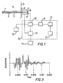
- Figure 1 illustrates a schematic representation of a ground anchorage integrity testing system using the present invention;
- Figure 2 illustrates an impulse imparting apparatus embodying the present invention; and
- Figure 3 illustrates a typical accelerometer response signature for an un-tensioned multi strand anchorage.
-
- To provide the necessary support, a ground anchorage is installed and the tension T thereon is increased to a predetermined tension Tmax appropriate for supporting the structure in question. Thereafter, the value of T(t) is a function of time and will vary from Tmax. The ground anchorage integrity testing system of the present invention intends to facilitate the assessment of the value of T(t) by considering the deviation from Tmax.
- Referring to figure 1, a
bore hole 3 is drilled intorock 4 through the rock surface 5. Aground anchorage tendon 2 having a length of 30 metres is inserted into the bore hole. Then, a cement grout is inserted to bond an end length 1 of theanchorage tendon 2 to therock 4. The space between the remaining length of the anchorage tendon and the rock can be filled with a grout in known manner. Atensioning assembly 6 is located at the anchorage at the rock surface 5. An impulse imparting apparatus 7 is located over the anchorage tendon to impart a load impulse against animpulse plate 8 attached to the anchorage tendon. Theimpulse plate 8 can form a part of the impulse imparting apparatus. Anaccelerometer 9 is attached to the impulse plate for detecting the vibrational response of the anchorage. Alternatively theaccelerometer 9 could be attached directly to the ground anchorage itself. - The output of the accelerometer is connected to the input of an
analysis unit 15. The signals received at the input are connected to adata acquisition stage 10 which in turn is connected to a statistical processing stage 11. The output from the statistical processing stage 11 is connected to an artificialneural network 12 which can access amemory 13. Theanalysis unit 15 is controlled by amicroprocessor 17 and is connected to adisplay 16 and aninput device 14 such as a keyboard. - The system shown in figure 1 operates as follows. The
bore hole 3 is made and theanchorage tendon 2 is installed and bonded to the rock. Then, the tensioning assembly and impulse imparting apparatus 7 are mounted to theanchorage tendon 2 together with theimpulse plate 8. Thereafter, the anchorage tendon is tensioned to 10% of Tmax. At this point, themicroprocessor 17 actuates the load imparting apparatus 7 to provide a suitable load impulse against theimpact plate 8 to give a useful vibrational response. Themicroprocessor 17 controls thedata acquisition stage 10 so that the vibration signals from theaccelerometer 9 are captured when a predefined trigger point is achieved. Once the trigger point has been activated, the incoming signal is sampled and filtered to remove noise and unwanted signal attributes. - The output of the data acquisition stage is displayed on the
display 16 in both a time and frequency domain format so as to aid the user in selection of data suitable for identification by the unit. - In addition, the output of the
data acquisition stage 10 is processed by the statistical stage 11 using a series of mathematical and statistical procedures. This pre-processing uses several techniques such as principal component analysis, wavelet transforms, and higher order spectral analysis. With this use of pre-processing of the signal, it is possible to extract the maximum amount of detail about pertinent aspects of the vibrational response signature whilst minimising unwanted information and noise. Accordingly, the operation of the subsequent artificial neural network is much more accurate in the classification of the vibrational response signatures. - The output of the statistical stage 11 is then relayed to the artificial neural network. The artificial neural network used in the specific embodiment is known as a multi layer perceptron which utilises a supervised learning algorithm called back propagation. This enables the classification of inputs that are not linearly separable and have complicated relationships which are difficult to define with other means. The classification and information regarding the signature is stored in the
memory 13. - The
microprocessor 17 controls the impulse imparting apparatus 7 such that a series of 20 load impulses are applied to the tensioned anchorage. The number of load impulses can be varied to be different from 20. The optimum vibrational response signatures are selected and processed by the neural network and classified as 10% Tmax for that location of the anchorage. - Thereafter, the tension on the anchorage is increased by a further 10% Tmax and the exercise of 20 load impulses is repeated. When the tension reaches 80% Tmax, the increase in tension is reduced to 2% Tmax before repeating the exercise. Eventually, the tension reaches Tmax and the anchorage is correctly supporting the structure. The increase in tension can be varied to be different from 2%.
- Thus, the artificial neural network has a series of signatures classified according to the anchorage in question and according to tension. The exercise is repeated for a large number of identical anchorages at that location so that the artificial neural network learns to classify the vibrational response signatures with more and more accuracy.
- By taking samples in this way with the classification obtained by the system, it possible to obtain an improved classification and obtain a higher accuracy of subsequent changes in the integrity of the ground anchorage.
- At a later time, for example 6 months later, the system can again be used on the now pre-tensioned anchorages. The exercise of applying a series of 20 load impulses to the anchorages is repeated and by comparison with the classified vibrational response signatures for that anchorage and location in the
memory 13 associated with the artificial neural network, it is possible to identify whether there has been a change in the tension on the anchorage tested from the optimum value Tmax. The use of the aforementioned pre-processing step enables identification of the condition of ground anchorages under test with much greater success than hitherto known, and in particular with respect of ground anchorages in excess of say 10 metres. - As described above, to classify and to assess the pre-tension on an anchorage, it is necessary to apply a load impulse I to the ground anchorage tendon. However, it is important that the load impulse I is not more than 20% of Tmax since otherwise damage to the anchorage may occur. It has been found that I is preferably 5 to 20% of Tmax. However, the value of I will change according to the value of Tmax for the anchorage in question. Thus, it is important that the load impulse imparting apparatus can easily change the value of the applied load impulse I. Moreover, as mentioned above, in order to obtain a more accurate classification of the vibrational response signature, 20 load impulses are applied to the anchorage to obtain a corresponding number of signatures. Furthermore, for long anchorages in excess of 10 metres, the load impulse applied to the anchorage must be large to obtain a valid vibrational response. Finally, the load impulse imparting apparatus should be able to apply the load impulse to individual strands of a multi strand anchorage tendon.
- It has been found that the damping of the vibrational response signature increases with increases in pre-tensioning. By comparing the first 6 peaks of the positive damping envelope over a range of pre-tension levels, it can clearly be seen that the rate of decay of the response signature increases with pre-tension. This makes it possible to differentiate between the various pre-tension levels. In addition, a fast Fourier Transform on the response signatures indicated a change in the main frequency component with a change in pre-tension.
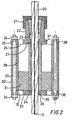
- Figure 2 illustrates an impulse imparting apparatus embodying the present invention which can impart a load impulse to strands of a multi strand ground anchorage. It will be appreciated that the apparatus can be readily adapted to apply a load impulse to a rod anchorage by having a threaded attachment on the apparatus for screwing the apparatus to the anchorage tendon.
- Referring to figure 2, the apparatus has an
outer cylinder 28 with a firstcircular end plate 25 at one end and a secondcircular end plate 33 at the other end. Theouter cylinder 28 defines the axis O of the apparatus and locates with an annular recess (not shown) formed in the facing surfaces of the first andsecond end plates inner cylinder 34 extends along this axis and is held in place by furtherannular recesses inner cylinder 34 corresponds to the diameter of atendon 20 of the anchorage to be tested, in this example, a component or strand of a multi strand anchorage. The outer diameter of the inner cylinder substantially corresponds to the diameter of the central aperture in anannular mass 31 which slides along the inner cylinder. The outer diameter of theannular mass 31 substantially corresponds with the inner diameter of theouter cylinder 28 . Thus, the annular mass can slide along and be guided by the inner cylinder and also forms a generally airtight seal against both the inner cylinder and outer cylinder. - The
first end plate 25 is formed with an anchorage attachment 22. In the present embodiment, this takes the form of a tube integrally formed with the first plate to extend away from the plane of the plate. The tube has an axially located bore with a diameter increasing away from the plane of thefirst end plate 25 as illustrated. The bore lines up with anaperture 37 centrally located in the first end plate through which theanchorage tendon 20 passes. A plurality of throughapertures 26 are formed in the first end plate around the apparatus axis as exhaust ports. - The
second end plate 33 also has anaperture 36 centrally located therein through which theanchorage tendon 20 passes. A plurality of throughapertures 32 are formed in the second end plate around the apparatus axis as inlet ports. - Both the first and second end plates extend radially beyond the diameter of the outer cylinder and have a plurality of circumferential through
apertures 38 at this point. A series ofrods 29, which are threaded at both ends, are located through the apertures in both end plates.Nuts 24 are located on the threaded ends of each rod and are tightened to force or clamp the end plates together thereby holding the outer and inner cylinders in place. Anouter sleeve 30 is provided around the rods. - In use, the apparatus is located over a strand of a multi strand anchorage to be tested. Then, a set of tapered
wedges 23, which are serrated on their axially inwardly facing surfaces, are inserted into the anchorage tendon attachment 22 and are pushed towards the first end plate by a threadedcollar 21 which screws onto a corresponding thread formed on the outwardly facing surface of the anchorage tendon attachment 22. Thus, the apparatus grips the strand of the multi strand anchorage so that the apparatus is operatively associated with the anchorage for applying or coupling a load impulse to the anchorage. - A source of compressed air is connected to the inlet ports via switching valves (not shown) controlled by the
microprocessor 17. When a load impulse is to be applied to the anchorage, the microprocessor controls the switching valves to introduce compressed air through the inlet ports. This drives the mass to move rapidly from a location adjacent the second end plate towards the first end plate to impact thereon, the movement of the mass being guided by the inner cylinder. Air already within the outer cylinder is expelled from the exhaust ports. - The impact of the
annular mass 31 on thefirst end plate 25 produces a force or load impulse which is operatively coupled to the anchorage tendon away from the bonding point in the ground. The mass will then rebound from the first end plate. In order to avoid a second impulse being created on impact with the second end plate, a compression spring (not shown) can be located between theannular mass 31 and thesecond end plate 35 to damp the rebounding mass. Removal of the spring also facilitates a simple change in the stroke length. - The maximum size of the impulse force can be estimated by the formula:-
- Figure 3 illustrates a typical accelerometer response signature for an un-tensioned multi strand anchorage. The values used for the apparatus were as follows:-
- m = 2 Kg
- I = 140 mm
- P = 196,2·103 Pa (2 Bar)
- A = 5 x 10⁻³ m2
- Δt = 0.1 ms
-
- By driving the mass in this way, it is possible to apply large load impulses to the anchorage sufficient to obtain suitable vibrational response signatures from anchorages in at least the
range 10 to 30 metres. Furthermore, the magnitude of the load impulse can be easily varied by controlling the value of P making the apparatus versatile to use. Further variations can be obtained by varying the value of m. It will be understood that the value of m and A will tend to vary since the diameter of the anchorage tendon will change necessitating changes in the inner cylinder, anchorage attachment and mass. - In this respect, it will be appreciated that the apparatus can be easily taken apart to enable different size inner cylinders to be used, different weight masses to be used, different anchorage attachments to be used (for example, a threaded anchorage attachment 22 for attachment to rod anchorages), and to enable variation of the stroke.
- In addition, by using a driving force to move the mass, the apparatus can be used from a remote location once the apparatus has been installed. Moreover, it is possible to easily apply a number of load impulses to make the calibration and testing of anchorages very much easier than hitherto. Furthermore, by using the anchorage attachment of the present invention, the apparatus can be used for applying load impulses to strands of multi strand anchorages.
- It will be apparent that the present invention can take many forms within the scope of the claims, the detailed embodiments of which will be readily apparent to a person skilled in the art. For example, hydraulics could be used to drive the mass in the impulse imparting apparatus or an electrical version could be devised.
Claims (6)
- A system enabling a user to remotely apply a load impulse to a ground anchorage tendon (2, 20) or element thereof to be tested, the system comprising:-an impact receiver (8, 25) securable relative to the tendon or element thereof so as to operatively transmit mechanical energy therebetween;a tubular member (34), associated with the impact receiver, encircling the tendon or element thereof and restrained against axial motion relative thereto;an annular mass (31), disposed coaxially with the tubular member, the mass being capable of sliding movement along the tubular member and being guided thereby towards the impact receiver from an initial position spaced therefrom;power means (17, 32,33), actuatable remotely from the tendon or element thereof, for applying a particular motive force to the mass to cause the mass to move from said initial position and to collide with the impact receiver thereby generating the load impulse and operatively transmitting it to the tendon or element thereof; andsensor means (9) for detecting the vibrational response of the tendon or element thereof to the load impulse and for generating electrical signals indicative of the response.
- A system according to claim 1 wherein said power means is operable to vary the magnitude of the motive force by means of which the annular mass is driven along the tubular member.
- A system according to claim 1 or claim 2 wherein said power means is operable to vary the distance for which the annular mass is driven along the tubular member.
- A system according to any preceding claim comprising a further relatively larger tubular member (28) coaxially aligned with the first-mentioned tubular member (34); wherein the annular mass (31) has an outer diameter substantially the same as the inner diameter of the relatively large tubular member.
- A system according to any preceding claim wherein said power means comprises a valve arrangement for connecting to a source of hydraulic or pneumatic power.
- A system according to any one of claims 1 to 4 wherein said power means comprises a switch arrangement for connecting to a source of electrical power.
Priority Applications (2)
| Application Number | Priority Date | Filing Date | Title |
|---|---|---|---|
| DK03075813.0T DK1324031T3 (en) | 1997-04-29 | 1998-04-28 | Method for testing soil anchoring using vibration analysis |
| EP03075813A EP1324031B1 (en) | 1997-04-29 | 1998-04-28 | Ground anchorage testing method by vibration analysis |
Applications Claiming Priority (3)
| Application Number | Priority Date | Filing Date | Title |
|---|---|---|---|
| GB9708740 | 1997-04-29 | ||
| GBGB9708740.7A GB9708740D0 (en) | 1997-04-29 | 1997-04-29 | Ground anchorage testing system |
| PCT/GB1998/001231 WO1998049553A1 (en) | 1997-04-29 | 1998-04-28 | Ground anchorage testing system |
Related Child Applications (1)
| Application Number | Title | Priority Date | Filing Date |
|---|---|---|---|
| EP03075813A Division EP1324031B1 (en) | 1997-04-29 | 1998-04-28 | Ground anchorage testing method by vibration analysis |
Publications (2)
| Publication Number | Publication Date |
|---|---|
| EP0979406A1 EP0979406A1 (en) | 2000-02-16 |
| EP0979406B1 true EP0979406B1 (en) | 2003-12-03 |
Family
ID=10811569
Family Applications (2)
| Application Number | Title | Priority Date | Filing Date |
|---|---|---|---|
| EP03075813A Expired - Lifetime EP1324031B1 (en) | 1997-04-29 | 1998-04-28 | Ground anchorage testing method by vibration analysis |
| EP98919322A Expired - Lifetime EP0979406B1 (en) | 1997-04-29 | 1998-04-28 | Ground anchorage testing system |
Family Applications Before (1)
| Application Number | Title | Priority Date | Filing Date |
|---|---|---|---|
| EP03075813A Expired - Lifetime EP1324031B1 (en) | 1997-04-29 | 1998-04-28 | Ground anchorage testing method by vibration analysis |
Country Status (12)
| Country | Link |
|---|---|
| US (2) | US6422079B1 (en) |
| EP (2) | EP1324031B1 (en) |
| JP (1) | JP3875729B2 (en) |
| AT (2) | ATE442583T1 (en) |
| AU (1) | AU741914B2 (en) |
| CA (1) | CA2289064C (en) |
| DE (2) | DE69841144D1 (en) |
| DK (1) | DK1324031T3 (en) |
| ES (2) | ES2333310T3 (en) |
| GB (1) | GB9708740D0 (en) |
| PT (2) | PT1324031E (en) |
| WO (1) | WO1998049553A1 (en) |
Cited By (1)
| Publication number | Priority date | Publication date | Assignee | Title |
|---|---|---|---|---|
| CN112095596A (en) * | 2020-11-03 | 2020-12-18 | 成都诺比侃科技有限公司 | Intelligent monitoring and early warning system and method for slope prestressed anchor rod based on cloud platform |
Families Citing this family (20)
| Publication number | Priority date | Publication date | Assignee | Title |
|---|---|---|---|---|
| GB0101043D0 (en) * | 2001-01-15 | 2001-02-28 | Univ Aberdeen | Input parameter selection process |
| ZA200405176B (en) * | 2003-06-30 | 2005-04-26 | Csir | Method and apparatus for testing installation quality in a grouted anchor system |
| DE102004036650B4 (en) | 2004-07-28 | 2007-10-31 | Bene_Fit Gmbh | Process for the preparation of colored granules and colored granules |
| US9534993B2 (en) | 2010-11-01 | 2017-01-03 | Purdue Research Foundation | Entropy-based impact load identification |
| JP6128432B2 (en) * | 2013-04-09 | 2017-05-17 | 三井造船株式会社 | Anchor soundness inspection device and anchor soundness inspection method |
| JP6191231B2 (en) * | 2013-05-16 | 2017-09-06 | 株式会社大林組 | Pile soundness evaluation method |
| JP6681776B2 (en) * | 2016-04-18 | 2020-04-15 | 西日本高速道路株式会社 | Ground anchor soundness evaluation method and soundness evaluation system |
| CN106501465B (en) * | 2016-12-23 | 2018-11-13 | 石家庄铁道大学 | A kind of detection method for detecting Detection of Bolt Bonding Integrity |
| FR3062862B1 (en) * | 2017-02-13 | 2019-04-05 | Soletanche Freyssinet | ANCHORING DEVICE FOR PRECONTROLLED MOLDED WALL |
| DE102017114651A1 (en) * | 2017-06-30 | 2019-01-03 | Rudi Hachenberg | Method and device for assessing the connection quality of anchor devices |
| CN108086369B (en) * | 2018-02-11 | 2023-09-12 | 广东工业大学 | Device and method for measuring pile soil combined action displacement stress under different rock-socketed depths |
| CN110031175B (en) * | 2019-03-20 | 2020-03-31 | 东南大学 | Bolt connecting piece equivalent model parameter identification method based on dynamic response |
| CN109975048B (en) * | 2019-03-26 | 2023-12-26 | 昆山顺扬工业成套设备有限公司 | Testing device of comprehensive training device |
| CN110826598B (en) * | 2019-10-16 | 2022-09-02 | 四川大学 | Anchor rod anchoring compactness grade evaluation method based on convolutional neural network |
| US11454559B2 (en) | 2019-11-20 | 2022-09-27 | Engineering Innovations, LLC | System and method of testing the tension of anchors in a dam |
| CN111257415B (en) * | 2020-01-17 | 2021-08-10 | 同济大学 | Tunnel damage detection management system based on mobile train vibration signal |
| CN111141596B (en) * | 2020-02-19 | 2022-06-17 | 安徽理工大学 | Mechanical performance testing device under impact load action of anchoring body and use method |
| CN112067220B (en) * | 2020-09-10 | 2021-11-16 | 泰安泰烁岩层控制科技有限公司 | Clamping piece type anchorage vibration test device and application thereof |
| CN112832305A (en) * | 2021-01-07 | 2021-05-25 | 淮北九天测绘股份有限公司 | Foundation pit slope stability dynamic monitoring device |
| CN114592480B (en) * | 2022-03-11 | 2023-06-13 | 重庆三峡学院 | Method and device for preventing and controlling landslide of reservoir bank |
Family Cites Families (6)
| Publication number | Priority date | Publication date | Assignee | Title |
|---|---|---|---|---|
| US4062229A (en) * | 1977-02-22 | 1977-12-13 | General Electric Company | Method of testing the integrity of installed rock bolts |
| US4967587A (en) * | 1989-10-20 | 1990-11-06 | Combustion Engineering, Inc. | Impact calibration tool |
| US5165270A (en) * | 1990-12-31 | 1992-11-24 | Sansalone Mary J | Non-destructive materials testing apparatus and technique for use in the field |
| JP3100757B2 (en) * | 1992-06-02 | 2000-10-23 | 三菱電機株式会社 | Monitoring and diagnostic equipment |
| GB9406745D0 (en) * | 1994-04-06 | 1994-05-25 | Aberdeen University And Univer | Integrity assessment of ground anchorages |
| US5774376A (en) * | 1995-08-07 | 1998-06-30 | Manning; Raymund A. | Structural health monitoring using active members and neural networks |
-
1997
- 1997-04-29 GB GBGB9708740.7A patent/GB9708740D0/en active Pending
-
1998
- 1998-04-28 JP JP54673998A patent/JP3875729B2/en not_active Expired - Fee Related
- 1998-04-28 DK DK03075813.0T patent/DK1324031T3/en active
- 1998-04-28 PT PT03075813T patent/PT1324031E/en unknown
- 1998-04-28 PT PT98919322T patent/PT979406E/en unknown
- 1998-04-28 DE DE69841144T patent/DE69841144D1/en not_active Expired - Lifetime
- 1998-04-28 ES ES03075813T patent/ES2333310T3/en not_active Expired - Lifetime
- 1998-04-28 AU AU72202/98A patent/AU741914B2/en not_active Ceased
- 1998-04-28 DE DE69820253T patent/DE69820253T2/en not_active Expired - Lifetime
- 1998-04-28 US US09/403,913 patent/US6422079B1/en not_active Expired - Lifetime
- 1998-04-28 EP EP03075813A patent/EP1324031B1/en not_active Expired - Lifetime
- 1998-04-28 WO PCT/GB1998/001231 patent/WO1998049553A1/en active IP Right Grant
- 1998-04-28 CA CA002289064A patent/CA2289064C/en not_active Expired - Lifetime
- 1998-04-28 AT AT03075813T patent/ATE442583T1/en active
- 1998-04-28 ES ES98919322T patent/ES2212290T3/en not_active Expired - Lifetime
- 1998-04-28 EP EP98919322A patent/EP0979406B1/en not_active Expired - Lifetime
- 1998-04-28 AT AT98919322T patent/ATE255724T1/en active
-
2002
- 2002-04-12 US US10/121,752 patent/US20030015038A1/en not_active Abandoned
Cited By (1)
| Publication number | Priority date | Publication date | Assignee | Title |
|---|---|---|---|---|
| CN112095596A (en) * | 2020-11-03 | 2020-12-18 | 成都诺比侃科技有限公司 | Intelligent monitoring and early warning system and method for slope prestressed anchor rod based on cloud platform |
Also Published As
| Publication number | Publication date |
|---|---|
| US20030015038A1 (en) | 2003-01-23 |
| ATE255724T1 (en) | 2003-12-15 |
| EP0979406A1 (en) | 2000-02-16 |
| AU741914B2 (en) | 2001-12-13 |
| PT979406E (en) | 2004-04-30 |
| EP1324031A2 (en) | 2003-07-02 |
| GB9708740D0 (en) | 1997-06-18 |
| AU7220298A (en) | 1998-11-24 |
| PT1324031E (en) | 2010-01-05 |
| EP1324031A3 (en) | 2004-10-06 |
| DE69820253D1 (en) | 2004-01-15 |
| JP3875729B2 (en) | 2007-01-31 |
| ES2212290T3 (en) | 2004-07-16 |
| CA2289064C (en) | 2008-01-15 |
| WO1998049553A1 (en) | 1998-11-05 |
| DK1324031T3 (en) | 2010-01-25 |
| JP2001522458A (en) | 2001-11-13 |
| ES2333310T3 (en) | 2010-02-19 |
| US6422079B1 (en) | 2002-07-23 |
| DE69841144D1 (en) | 2009-10-22 |
| EP1324031B1 (en) | 2009-09-09 |
| DE69820253T2 (en) | 2004-09-16 |
| ATE442583T1 (en) | 2009-09-15 |
| CA2289064A1 (en) | 1998-11-05 |
Similar Documents
| Publication | Publication Date | Title |
|---|---|---|
| EP0979406B1 (en) | Ground anchorage testing system | |
| US6804994B2 (en) | Dynamic loading system, dynamic loading method and dynamic loading test method for piles | |
| US5821430A (en) | Method and apparatus for conducting in-situ nondestructive tensile load measurements in cables and ropes | |
| CN101918850B (en) | Method and device for calibrating acceleration and force sensors | |
| AU2004202923B2 (en) | Method and Apparatus for Testing Installation Quality in a Grouted Anchor System | |
| WO2005066421A1 (en) | Testing method and apparatus ground liquefaction and dynamic characteristics in original position utilizing boring hole | |
| US4152929A (en) | Roof bolt tension determination | |
| JPS63186122A (en) | Abnormality diagnosing system for structure | |
| JP2005148064A (en) | Device and method for detecting change or damage to pressure vessel during or after pressure test | |
| Carne et al. | Lessons learned in modal testing—part 3: Transient excitation for modal testing, more than just hammer impacts | |
| CN107894443A (en) | It is a kind of to be used to monitor anchoring elastic piezoelectric ceramics system and monitoring method | |
| KR100958405B1 (en) | Non-destructive measurement method of pullout resistance in cable structures and device for the same | |
| CN107024308A (en) | A kind of method of testing of intermediate plate anchorage snap-in force | |
| Deckers et al. | Modal testing of bridges using low-weight pneumatic artificial muscle actuators | |
| JP6504964B2 (en) | Member condition evaluation device and condition evaluation method | |
| CN215492331U (en) | Active excitation type bridge cable detection device | |
| RU2773228C2 (en) | Method for controlled assembly of threaded connections and apparatus for implementation thereof | |
| SU1314253A1 (en) | Device for studying bauschinger effect in high-speed deforming of solids | |
| RU2443867C1 (en) | Method to control engagement of bolting with rock massif and device for its realisation | |
| SU1663468A1 (en) | Stand for dynamic testing | |
| CN113465855A (en) | Active excitation type bridge cable detection device and detection method | |
| Deckers et al. | Implementation of the scanning laser Doppler vibrometer combined with a light-weight pneumatic artificial muscle actuator for the modal analysis of a civil structure | |
| PL208391B1 (en) | Method for checking the quality of anchor rod mounting in the rock mass and apparatus employing this method | |
| KR20160034452A (en) | Band for exciting the bridge cable, method for evaluating the damping characteristics using the band |
Legal Events
| Date | Code | Title | Description |
|---|---|---|---|
| PUAI | Public reference made under article 153(3) epc to a published international application that has entered the european phase |
Free format text: ORIGINAL CODE: 0009012 |
|
| 17P | Request for examination filed |
Effective date: 19991108 |
|
| AK | Designated contracting states |
Kind code of ref document: A1 Designated state(s): AT BE CH CY DE DK ES FI FR GB GR IE IT LI LU MC NL PT SE |
|
| 17Q | First examination report despatched |
Effective date: 20010507 |
|
| GRAH | Despatch of communication of intention to grant a patent |
Free format text: ORIGINAL CODE: EPIDOS IGRA |
|
| GRAS | Grant fee paid |
Free format text: ORIGINAL CODE: EPIDOSNIGR3 |
|
| GRAA | (expected) grant |
Free format text: ORIGINAL CODE: 0009210 |
|
| AK | Designated contracting states |
Kind code of ref document: B1 Designated state(s): AT BE CH CY DE DK ES FI FR GB GR IE IT LI LU MC NL PT SE |
|
| PG25 | Lapsed in a contracting state [announced via postgrant information from national office to epo] |
Ref country code: CY Free format text: LAPSE BECAUSE OF FAILURE TO SUBMIT A TRANSLATION OF THE DESCRIPTION OR TO PAY THE FEE WITHIN THE PRESCRIBED TIME-LIMIT Effective date: 20031203 |
|
| REG | Reference to a national code |
Ref country code: GB Ref legal event code: FG4D |
|
| RIN1 | Information on inventor provided before grant (corrected) |
Inventor name: PENMAN, JAMES Inventor name: NEILSON, RICHARD, DAVID Inventor name: LITTLEJOHN, GAVIN, STUART Inventor name: RODGER, ALBERT, ALEXANDER |
|
| REG | Reference to a national code |
Ref country code: CH Ref legal event code: EP |
|
| RAP2 | Party data changed (patent owner data changed or rights of a patent transferred) |
Owner name: UNIVERSITY OF BRADFORD Owner name: ABERDEEN UNIVERSITY |
|
| REG | Reference to a national code |
Ref country code: IE Ref legal event code: FG4D |
|
| REF | Corresponds to: |
Ref document number: 69820253 Country of ref document: DE Date of ref document: 20040115 Kind code of ref document: P |
|
| NLT2 | Nl: modifications (of names), taken from the european patent patent bulletin |
Owner name: ABERDEEN UNIVERSITY EN UNIVERSITY OF BRADFORD |
|
| PG25 | Lapsed in a contracting state [announced via postgrant information from national office to epo] |
Ref country code: DK Free format text: LAPSE BECAUSE OF FAILURE TO SUBMIT A TRANSLATION OF THE DESCRIPTION OR TO PAY THE FEE WITHIN THE PRESCRIBED TIME-LIMIT Effective date: 20040303 |
|
| REG | Reference to a national code |
Ref country code: SE Ref legal event code: TRGR |
|
| RAP2 | Party data changed (patent owner data changed or rights of a patent transferred) |
Owner name: UNIVERSITY OF BRADFORD Owner name: ABERDEEN UNIVERSITY |
|
| REG | Reference to a national code |
Ref country code: CH Ref legal event code: NV Representative=s name: R. A. EGLI & CO. PATENTANWAELTE |
|
| REG | Reference to a national code |
Ref country code: GR Ref legal event code: EP Ref document number: 20040400703 Country of ref document: GR |
|
| PG25 | Lapsed in a contracting state [announced via postgrant information from national office to epo] |
Ref country code: LU Free format text: LAPSE BECAUSE OF NON-PAYMENT OF DUE FEES Effective date: 20040428 |
|
| PG25 | Lapsed in a contracting state [announced via postgrant information from national office to epo] |
Ref country code: MC Free format text: LAPSE BECAUSE OF NON-PAYMENT OF DUE FEES Effective date: 20040430 |
|
| REG | Reference to a national code |
Ref country code: PT Ref legal event code: SC4A Free format text: AVAILABILITY OF NATIONAL TRANSLATION Effective date: 20040302 |
|
| NLT2 | Nl: modifications (of names), taken from the european patent patent bulletin |
Owner name: ABERDEEN UNIVERSITY EN UNIVERSITY OF BRADFORD |
|
| REG | Reference to a national code |
Ref country code: ES Ref legal event code: FG2A Ref document number: 2212290 Country of ref document: ES Kind code of ref document: T3 |
|
| ET | Fr: translation filed | ||
| PLBE | No opposition filed within time limit |
Free format text: ORIGINAL CODE: 0009261 |
|
| STAA | Information on the status of an ep patent application or granted ep patent |
Free format text: STATUS: NO OPPOSITION FILED WITHIN TIME LIMIT |
|
| 26N | No opposition filed |
Effective date: 20040906 |
|
| PGFP | Annual fee paid to national office [announced via postgrant information from national office to epo] |
Ref country code: CH Payment date: 20120430 Year of fee payment: 15 Ref country code: IE Payment date: 20120423 Year of fee payment: 15 Ref country code: NL Payment date: 20120501 Year of fee payment: 15 |
|
| PGFP | Annual fee paid to national office [announced via postgrant information from national office to epo] |
Ref country code: SE Payment date: 20120427 Year of fee payment: 15 Ref country code: BE Payment date: 20120531 Year of fee payment: 15 Ref country code: FI Payment date: 20120424 Year of fee payment: 15 Ref country code: GR Payment date: 20120430 Year of fee payment: 15 Ref country code: FR Payment date: 20120608 Year of fee payment: 15 |
|
| PGFP | Annual fee paid to national office [announced via postgrant information from national office to epo] |
Ref country code: IT Payment date: 20120420 Year of fee payment: 15 |
|
| PGFP | Annual fee paid to national office [announced via postgrant information from national office to epo] |
Ref country code: ES Payment date: 20120530 Year of fee payment: 15 Ref country code: DE Payment date: 20120702 Year of fee payment: 15 |
|
| PGFP | Annual fee paid to national office [announced via postgrant information from national office to epo] |
Ref country code: PT Payment date: 20120423 Year of fee payment: 15 |
|
| PGFP | Annual fee paid to national office [announced via postgrant information from national office to epo] |
Ref country code: AT Payment date: 20120425 Year of fee payment: 15 |
|
| BERE | Be: lapsed |
Owner name: *UNIVERSITY OF BRADFORD Effective date: 20130430 Owner name: *ABERDEEN UNIVERSITY Effective date: 20130430 |
|
| REG | Reference to a national code |
Ref country code: PT Ref legal event code: MM4A Free format text: LAPSE DUE TO NON-PAYMENT OF FEES Effective date: 20131028 |
|
| REG | Reference to a national code |
Ref country code: NL Ref legal event code: V1 Effective date: 20131101 |
|
| REG | Reference to a national code |
Ref country code: CH Ref legal event code: PL |
|
| REG | Reference to a national code |
Ref country code: SE Ref legal event code: EUG |
|
| REG | Reference to a national code |
Ref country code: AT Ref legal event code: MM01 Ref document number: 255724 Country of ref document: AT Kind code of ref document: T Effective date: 20130430 |
|
| REG | Reference to a national code |
Ref country code: GR Ref legal event code: ML Ref document number: 20040400703 Country of ref document: GR Effective date: 20131104 |
|
| REG | Reference to a national code |
Ref country code: IE Ref legal event code: MM4A |
|
| PG25 | Lapsed in a contracting state [announced via postgrant information from national office to epo] |
Ref country code: SE Free format text: LAPSE BECAUSE OF NON-PAYMENT OF DUE FEES Effective date: 20130429 Ref country code: DE Free format text: LAPSE BECAUSE OF NON-PAYMENT OF DUE FEES Effective date: 20131101 Ref country code: PT Free format text: LAPSE BECAUSE OF NON-PAYMENT OF DUE FEES Effective date: 20131028 Ref country code: BE Free format text: LAPSE BECAUSE OF NON-PAYMENT OF DUE FEES Effective date: 20130430 Ref country code: AT Free format text: LAPSE BECAUSE OF NON-PAYMENT OF DUE FEES Effective date: 20130430 Ref country code: LI Free format text: LAPSE BECAUSE OF NON-PAYMENT OF DUE FEES Effective date: 20130430 Ref country code: CH Free format text: LAPSE BECAUSE OF NON-PAYMENT OF DUE FEES Effective date: 20130430 |
|
| REG | Reference to a national code |
Ref country code: FR Ref legal event code: ST Effective date: 20131231 |
|
| REG | Reference to a national code |
Ref country code: DE Ref legal event code: R119 Ref document number: 69820253 Country of ref document: DE Effective date: 20131101 |
|
| PG25 | Lapsed in a contracting state [announced via postgrant information from national office to epo] |
Ref country code: NL Free format text: LAPSE BECAUSE OF NON-PAYMENT OF DUE FEES Effective date: 20131101 Ref country code: FR Free format text: LAPSE BECAUSE OF NON-PAYMENT OF DUE FEES Effective date: 20130430 Ref country code: GR Free format text: LAPSE BECAUSE OF NON-PAYMENT OF DUE FEES Effective date: 20131104 Ref country code: FI Free format text: LAPSE BECAUSE OF NON-PAYMENT OF DUE FEES Effective date: 20130428 Ref country code: IT Free format text: LAPSE BECAUSE OF NON-PAYMENT OF DUE FEES Effective date: 20130428 |
|
| PG25 | Lapsed in a contracting state [announced via postgrant information from national office to epo] |
Ref country code: IE Free format text: LAPSE BECAUSE OF NON-PAYMENT OF DUE FEES Effective date: 20130428 |
|
| REG | Reference to a national code |
Ref country code: ES Ref legal event code: FD2A Effective date: 20140610 |
|
| PG25 | Lapsed in a contracting state [announced via postgrant information from national office to epo] |
Ref country code: ES Free format text: LAPSE BECAUSE OF NON-PAYMENT OF DUE FEES Effective date: 20130429 |
|
| PGFP | Annual fee paid to national office [announced via postgrant information from national office to epo] |
Ref country code: GB Payment date: 20150428 Year of fee payment: 18 |
|
| GBPC | Gb: european patent ceased through non-payment of renewal fee |
Effective date: 20160428 |
|
| PG25 | Lapsed in a contracting state [announced via postgrant information from national office to epo] |
Ref country code: GB Free format text: LAPSE BECAUSE OF NON-PAYMENT OF DUE FEES Effective date: 20160428 |