EP0978914A1 - Lead seal block for protective circuit arrangements and series build-in switch - Google Patents
Lead seal block for protective circuit arrangements and series build-in switch Download PDFInfo
- Publication number
- EP0978914A1 EP0978914A1 EP99106230A EP99106230A EP0978914A1 EP 0978914 A1 EP0978914 A1 EP 0978914A1 EP 99106230 A EP99106230 A EP 99106230A EP 99106230 A EP99106230 A EP 99106230A EP 0978914 A1 EP0978914 A1 EP 0978914A1
- Authority
- EP
- European Patent Office
- Prior art keywords
- strip element
- housing
- opening
- section
- screwdriver
- Prior art date
- Legal status (The legal status is an assumption and is not a legal conclusion. Google has not performed a legal analysis and makes no representation as to the accuracy of the status listed.)
- Withdrawn
Links
Images


Classifications
-
- H—ELECTRICITY
- H01—ELECTRIC ELEMENTS
- H01H—ELECTRIC SWITCHES; RELAYS; SELECTORS; EMERGENCY PROTECTIVE DEVICES
- H01H9/00—Details of switching devices, not covered by groups H01H1/00 - H01H7/00
- H01H9/02—Bases, casings, or covers
- H01H9/0264—Protective covers for terminals
Definitions
- the invention relates to a device for secure cover of on a housing of an electrical protective switching device or a series installation switch provided and ins Widening screwdriver openings for conductor connection screws.
- the device is as a flat on the Housing attachable and attachable to this by sealing Last element formed, the at least two each for inserting into the extended section hook-shaped underside provided for the screwdriver opening Has formations, at least one spaced apart sealing opening formed by the projections in the strip element is provided.
- the hook-shaped formations advantageously engage behind the existing screwdriver openings widening inside the housing and use the space, which after turning the Screws is free.
- the handling of the device according to the invention is extraordinary easy because the sealing strip underneath the hook-shaped Formations spaced apart in the standard dimension and itself extends across all relevant screwdriver openings in such a way that in a preferred embodiment even a Contour formation on the housing compensated by the sealing strip can be, especially if the housing contour in Area of the screwdriver opening to the side of the housing and the sealing strip has a wedge-shaped cross section having.
- the strip element preferably has an approximately rectangular one Floor plan, the hook-shaped under one side edge Formations with screwdriver hole spacing are molded in this way are that a preferred intended angled widespread Contact section under the side edge of the last element protrudes.
- On the opposite long side of the last element is preferably at least one sealing opening in the center provided that congruent with an opening in a housing cap runs and through which a sealing wire for securing the sealing strip can be guided.
- the projections preferably have a rounded angled area on that in the common plant section passes, the width of the contact section being slight is smaller than the diameter of the screwdriver opening. Due to the provided rounding, the molding receives an extraordinary great dimensional stability.
- the projection has a vertical web opposite the angled area a contact surface or contact edge for the Has wall of the screwdriver opening.
- the projection has a vertical web opposite the angled area a contact surface or contact edge for the Has wall of the screwdriver opening.
- the device can be advantageous only move and decrease in one axis, the movement is reliably prevented by a sealing wire, which is secured by a seal. This can continue be advantageously provided that the sealing opening a Sealing wire recess has to the edge of the strip element leads so that the sealing wire does not have the upper contour of the last element protrudes.
- Figures 1 to 8 is a first embodiment Device 10 according to the invention shown, which consists of an approximately rectangular element 11, four in the screwdriver opening spaced hook-shaped projections on the underside 12 to 15 and a continuous sealing opening 16 with a lead wire recess 17 leading to the edge.
- the device is preferably made of plastic.
- the strip element 11 has, as in FIGS. 5 and 7, a wedge-shaped cross-section, the hook-shaped projections 12 in the area of the cross-sectional fan are molded on the underside.
- the last element points Long sides 18 and 21 and transverse sides 19 and 20, the Long side 21, in the area of which the hook-shaped projections 12 to 15 are attached on the underside, rounded in the transverse sides 19 and 20 merges and one of these transverse sides Rounding with a larger radius of curvature to the opposite Long side 18 leads.
- Figures 2 to 5 accordingly show a bottom view, a front view, a rear view and a side view of the device 10 in order to illustrate its structure in more detail.
- the hook-shaped formations 12 to 15 are how special easily recognizable in Figures 2 to 5, with a vertical Web section 25 is formed, which on its longitudinal side 18 facing vertical back of a contact edge for the wall a screwdriver opening is formed, which is shown in FIGS and 8 is recognizable.
- the web 26 closes in the direction of the side edge 21 a vertical semicircular arched wall 27 from which is an angled widened contact section 28 approximately parallel to the underside of the strip element 11 whose side edge 21 extends, as can be seen clearly in FIG. 1 is. It can advantageously be provided that the widened system section 28, the maximum slightly is smaller than the width of the screwdriver opening at its front edge is rounded and chamfered.
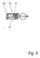
- Figure 7 shows schematically using a section through the Area of a screwdriver opening 30 that leads to the inside of the Housing 32 of an electrical protective switching device in one enlarged area 32 passes, the insertion of a hook-shaped Formation of the device 10 according to the invention, while Figure 8 shows a similar section in which the device 10 rests flush on the housing 32 with the strip element 11, and is sealed on it.
- Figure 9 shows a representation similar to Figure 6, a second Form of embodiment of a device 10 'according to the invention has only two hook-shaped formations, as described above and is attached by means of a seal.
Abstract
Description
Die Erfindung betrifft eine Vorrichtung zur sicherbaren Abdeckung von an einem Gehäuse eines elektrischen Schutzschaltgerätes bzw. eines Reiheneinbauschalters vorgesehenen und sich ins Gehäuse erweiternden Schraubendreheröffnungen für Leiteranschlußschrauben.The invention relates to a device for secure cover of on a housing of an electrical protective switching device or a series installation switch provided and ins Widening screwdriver openings for conductor connection screws.
Bei derartigen elektrischen Geräten ist es in bestimmten Fällen erforderlich, eine sogenannte Plombierleiste anzubringen, um einen Zugang zu Leiteranschlußschrauben zu kontrollieren bzw. zu verhindern. Bisher bekannte Lösungen zur Sicherung derartiger Leiteranschlußschrauben arbeiten mit entsprechenden gehäuseseitig angeformten Deckeln oder sind mehrteilig ausgebildet und besitzen Riegel zum Plombieren.With such electrical devices it is in certain cases required to attach a so-called sealing strip to to control access to conductor connection screws or to prevent. Previously known solutions for securing such Conductor connection screws work with the corresponding housing side molded lids or are multi-part and have bars for sealing.
Mit der Erfindung soll eine Vorrichtung der eingangs genannten Gattung verfügbar gemacht werden, die eine Sicherung derartiger Leiteranschlußschrauben ohne Änderung der vorhandenen Gehäuseform ermöglicht.With the invention, a device of the type mentioned Generic be made available, which is a backup of such Conductor connection screws without changing the existing housing shape enables.
Erfindungsgemäß wird diese Aufgabe durch die im Anspruch 1 genannten Merkmale gelöst. Bevorzugte Merkmale, die die Erfindung vorteilhaft weiterbilden, sind den nachgeordneten Ansprüchen zu entnehmen.According to the invention, this object is achieved by those mentioned in claim 1 Features resolved. Preferred features of the invention Advantageously, are the subordinate claims refer to.
Aufgrund der erfindungsgemäßen Ausgestaltung wird somit eine außerordentlich einfach aufgebaute und leicht herstellbare Plombierleiste verfügbar gemacht, die auch nachträglich bei allen bekannten Gehäuseformen derartiger Schutzschaltgeräte und Reiheneinbauschalter eingesetzt werden kann.Because of the configuration according to the invention, a extraordinarily simple and easy to manufacture Sealing strip made available, which can also be added later all known housing types of such protective switching devices and in-line switches can be used.
In günstiger Weise ist die Vorrichtung als ein flach auf dem Gehäuse anbringbares und an diesem durch Plombierung befestigbares Leistenelement ausgebildet, das wenigstens zwei jeweils für das hintergreifende Einsetzen in den erweiterten Abschnitt der Schraubendreheröffnung vorgesehene hakenförmige unterseitige Anformungen aufweist, wobei wenigstens eine beabstandet von den Anformungen in dem Leistenelement gebildete Plombieröffnung vorgesehen ist.Conveniently, the device is as a flat on the Housing attachable and attachable to this by sealing Last element formed, the at least two each for inserting into the extended section hook-shaped underside provided for the screwdriver opening Has formations, at least one spaced apart sealing opening formed by the projections in the strip element is provided.
Vorteilhaft hintergreifen die hakenförmigen Anformungen die vorhandenen sich ins Innere des Gehäuses erweiternden Schraubendreheröffnungen und nutzen den Raum, der nach Andrehen der Schrauben frei wird.The hook-shaped formations advantageously engage behind the existing screwdriver openings widening inside the housing and use the space, which after turning the Screws is free.
Die Handhabung der erfindungsgemäßen Vorrichtung ist außerordentlich einfach, da die Plombierleiste unterseitig die hakenförmigen Anformungen im Normmaß beabstandet aufweist und sich über alle relevanten Schraubendreheröffnungen derart erstreckt, daß bei einer bevorzugten Ausgestaltung sogar eine Kontureinformung an dem Gehäuse durch die Plombierleiste ausgeglichen werden kann, insbesondere wenn die Gehäusekontur im Bereich der Schraubendreheröffnung zur Seite des Gehäuses abfällt und die Plombierleiste einen keilförmigen Querschnitt aufweist.The handling of the device according to the invention is extraordinary easy because the sealing strip underneath the hook-shaped Formations spaced apart in the standard dimension and itself extends across all relevant screwdriver openings in such a way that in a preferred embodiment even a Contour formation on the housing compensated by the sealing strip can be, especially if the housing contour in Area of the screwdriver opening to the side of the housing and the sealing strip has a wedge-shaped cross section having.
Das Leistenelement besitzt bevorzugt einen annähernd rechteckigen Grundriß, wobei unter einem Seitenrand die hakenförmigen Anformungen im Schraubendreherlochmaß beabstandet so angeformt sind, daß ein vorzugsweise vorgesehener abgewinkelter verbreiteter Anlageabschnitt unter dem Seitenrand des Leistenelements vorragt. An der gegenüberliegenden Längsseite des Leistenelements ist bevorzugt mittig wenigstens eine Plombieröffnung vorgesehen, die deckungsgleich mit einer Öffnung in einer Gehäusekappe verläuft und durch die ein Plombierdraht zur Sicherung der Plombierleiste geführt werden kann.The strip element preferably has an approximately rectangular one Floor plan, the hook-shaped under one side edge Formations with screwdriver hole spacing are molded in this way are that a preferred intended angled widespread Contact section under the side edge of the last element protrudes. On the opposite long side of the last element is preferably at least one sealing opening in the center provided that congruent with an opening in a housing cap runs and through which a sealing wire for securing the sealing strip can be guided.
Die Anformungen weisen vorzugsweise einen gerundeten Abwinklungsbereich auf, der in den verbreiteten Anlageabschnitt übergeht, wobei die Breite des Anlageabschnitts geringfügig kleiner ist als der Durchmesser der Schraubendreheröffnung. Durch die vorgesehene Rundung erhält die Anformung eine außerordentlich große Formstabilität.The projections preferably have a rounded angled area on that in the common plant section passes, the width of the contact section being slight is smaller than the diameter of the screwdriver opening. Due to the provided rounding, the molding receives an extraordinary great dimensional stability.
Für ein lagesicheres Einsetzen der Plombierleiste ist es zudem nach einer weiteren Ausgestaltung der Erfindung günstig, wenn die Anformung einen vertikalen Steg aufweist, der gegenüber dem Abwinkelbereich eine Anlagefläche bzw. Anlagekante für die Wandung der Schraubendreheröffnung aufweist. Hierdurch sitzt die Anformung an der Rückseite des Steges sicher an der Wandung der Schraubendreheröffnung und greift andererseits mit dem verbreiteten Anlagenbereich und gegebenenfalls unter geringfügiger elastischer Verformung in den erweiterten Abschnitt der Schraubendreheröffnung.It is also for a secure insertion of the sealing strip According to a further embodiment of the invention, if the projection has a vertical web opposite the angled area a contact surface or contact edge for the Has wall of the screwdriver opening. Hereby sits the molding on the back of the web securely on the wall the screwdriver opening and engages on the other hand the widespread plant area and possibly less elastic deformation in the enlarged section the screwdriver opening.
Bedingt durch den Formschluß zwischen hakenförmiger Anformung und Schraubendreheröffnung läßt sich vorteilhaft die Vorrichtung nur in einer Achse bewegen und abnehmen, wobei die Bewegung zuverlässig durch einen Plombierdraht verhindert wird, welcher durch eine Plombe gesichert ist. Dabei kann weiterhin vorteilhaft vorgesehen sein, daß die Plombieröffnung eine Plombierdraht-Ausnehmung besitzt, die zum Rand des Leistenelements führt, damit der Plombierdraht nicht über die obere Kontur des Leistenelements vorsteht.Due to the form fit between the hook-shaped form and screwdriver opening, the device can be advantageous only move and decrease in one axis, the movement is reliably prevented by a sealing wire, which is secured by a seal. This can continue be advantageously provided that the sealing opening a Sealing wire recess has to the edge of the strip element leads so that the sealing wire does not have the upper contour of the last element protrudes.
Mit der erfindungsgemäßen Vorrichtung ist es somit vorteilhaft möglich, ohne Veränderung der Gehäuseform des elektrischen Schutzschaltgerätes bzw. des Reiheneinbauschaltgerätes, insbesondere eines FI-Schalters, eine zuverlässige Sicherung vorzusehen, die außerordentlich einfach herstellbar und einsetzbar ist. Günstig ist weiterhin, daß sich auch mit der Verwendung der Vorrichtung keine Einschränkungen der Anschlußmöglichkeiten ergeben, da Einspeisungen in geräteseitigen Buchsen und Klemmen und gleichzeitiger Sammelschienenanschluß nach wie vor möglich sind.It is therefore advantageous with the device according to the invention possible without changing the housing shape of the electrical Protective switching device or in-line switching device, in particular a residual current circuit breaker to provide a reliable fuse, which are extremely easy to manufacture and use is. It is also favorable that also with the use the device no restrictions on the connection options result because feeds in device-side sockets and Clamps and simultaneous busbar connection as before possible are.
Nachfolgend wird die Erfindung unter Bezugnahme auf die beigefügten Figuren näher erläutert. Es zeigen:
- Fig. 1
- eine Draufsicht eines ersten Ausführungsbeispiels einer erfindungsgemäßen Vorrichtung mit vier hakenförmigen Anformungen;
- Fig. 2
- eine Unteransicht der in Figur 1 gezeigten Vorrichtung;
- Fig. 3
- eine Ansicht auf das in Figur 1 dargestellte Ausführungsbeispiel in Blattebene von oben gesehen (Vorderansicht);
- Fig. 4
- eine Ansicht der Vorrichtung von Figur 1 in Blattrichtung von unten gesehen (Rückansicht);
- Fig. 5
- eine Ansicht der in Figur 1 dargestellten Vorrichtung von der Seite
- Fig. 6
- eine Ansicht ähnlich Figur 1 nach Einsetzen und Befestigen der Vorrichtung;
- Fig. 7
- eine Schnittdarstellung im Bereich einer Schraubendreheröffnung, die einem Zwischenstadium beim Einsetzen der hakenförmigen Anformungen zeigt;
- Fig. 8
- einen Schnitt entlang der Schnittlinie 8-8 in Figur 6 und
- Fig. 9
- ein weiteres Ausführungsbeispiel der Erfindung mit zwei hakenförmigen Anformungen.
- Fig. 1
- a plan view of a first embodiment of a device according to the invention with four hook-shaped projections;
- Fig. 2
- a bottom view of the device shown in Figure 1;
- Fig. 3
- a view of the embodiment shown in Figure 1 in sheet plane seen from above (front view);
- Fig. 4
- a view of the device of Figure 1 seen from below in the sheet direction (rear view);
- Fig. 5
- a view of the device shown in Figure 1 from the side
- Fig. 6
- a view similar to Figure 1 after insertion and attachment of the device;
- Fig. 7
- a sectional view in the region of a screwdriver opening, showing an intermediate stage in the insertion of the hook-shaped formations;
- Fig. 8
- a section along the section line 8-8 in Figure 6 and
- Fig. 9
- a further embodiment of the invention with two hook-shaped projections.
In Figuren 1 bis 8 ist ein erstes Ausführungsbeispiel einer
erfindungsgemäßen Vorrichtung 10 gezeigt, die aus einem annähernd
rechteckförmigen Element 11, vier im Schraubendreheröffnungsnormabstand
beabstandete unterseitige hakenförmige Anformungen
12 bis 15 sowie eine durchgehende Plombieröffnung 16
mit einer zum Rand führenden Plombierdrahtausnehmung 17 besteht.
Die Vorrichtung ist vorzugsweise aus Kunststoff hergestellt.
Das Leistenelement 11 besitzt, wie in den Figuren 5
und 7 erkennbar, einen keilförmigen Querschnitt, wobei die
hakenförmigen Anformungen 12 im Bereich der Querschnittsfächerung
unterseitig angeformt sind. Das Leistenelement weist
Längsseiten 18 und 21 und Querseiten 19 und 20 auf, wobei die
Längsseite 21, in deren Bereich die hakenförmigen Anformungen
12 bis 15 unterseitig angebracht sind, abgerundet in die Querseiten
19 und 20 übergeht und wobei von diesen Querseiten eine
Abrundung mit einem größeren Krümmungsradius zu der gegenüberliegenden
Längsseite 18 führt.In Figures 1 to 8 is a
Die Figuren 2 bis 5 zeigen entsprechend eine Unteransicht,
eine Vorderansicht, eine Rückansicht und eine Seitenansicht
der Vorrichtung 10, um deren Aufbau näher zu veranschaulichen.Figures 2 to 5 accordingly show a bottom view,
a front view, a rear view and a side view
of the
Die hakenförmigen Anformungen 12 bis 15 sind, wie besonders
gut in den Figuren 2 bis 5 erkennbar, mit einem vertikalen
Stegabschnitt 25 gebildet, der an seiner zur Längsseite 18
weisenden vertikalen Rückseite eine Anlagekante für die Wand
einer Schraubendreheröffnung gebildet, die in den Figuren 7
und 8 erkennbar ist.The hook-
An den Steg 26 schließt sich in Richtung auf die Seitenkante
21 eine senkrechte halbkreisförmig gewölbte Wand 27 an, von
der ein abgewinkelter verbreiterter Anlageabschnitt 28 sich
annähernd parallel zur Unterseite des Leistenelements 11 über
dessen Seitenrand 21 hinaus erstreckt, wie in Figur 1 gut ersichtlich
ist. Dabei kann vorteilhaft vorgesehen sein, daß der
verbreiterte Anlagenabschnitt 28, der maximal geringfügig
kleiner als die Breite der Schraubendreheröffnung ist, an seiner
vorderen Kante abgerundet und angefast ist.The
Figur 7 zeigt schematisiert anhand eines Schnittes durch den
Bereich einer Schraubendreheröffnung 30, die zum Inneren des
Gehäuses 32 eines elektrischen Schutzschaltgerätes in einen
erweiterten Bereich 32 übergeht, das Einsetzen einer hakenförmigen
Anformung der erfindungsgemäßen Vorrichtung 10, während
Figur 8 einen ähnlichen Schnitt zeigt, bei dem die Vorrichtung
10 auf dem Gehäuse 32 mit dem Leistenelement 11 bündig aufliegt,und
daran plombiert ist.Figure 7 shows schematically using a section through the
Area of a screwdriver opening 30 that leads to the inside of the
Figur 9 zeigt in einer Darstellung ähnlich Figur 6 eine zweite Ausbildungsform einer erfindungsgemäßen Vorrichtung 10', die nur zwei hakenförmige Anformungen, wie oben beschrieben, aufweist und mittels einer Plombierung befestigt ist.Figure 9 shows a representation similar to Figure 6, a second Form of embodiment of a device 10 'according to the invention has only two hook-shaped formations, as described above and is attached by means of a seal.
Claims (9)
gekennzeichnet durch
marked by
dadurch gekennzeichnet,
characterized,
dadurch gekennzeichnet,
characterized,
dadurch gekennzeichnet,
characterized,
dadurch gekennzeichnet,
characterized,
dadurch gekennzeichnet,
characterized,
dadurch gekennzeichnet,
characterized,
dadurch gekennzeichnet,
characterized,
dadurch gekennzeichnet,
characterized,
Applications Claiming Priority (2)
| Application Number | Priority Date | Filing Date | Title |
|---|---|---|---|
| DE29814053U | 1998-08-05 | ||
| DE29814053U DE29814053U1 (en) | 1998-08-05 | 1998-08-05 | Sealing strip for protective switching devices and modular installation switches |
Publications (1)
| Publication Number | Publication Date |
|---|---|
| EP0978914A1 true EP0978914A1 (en) | 2000-02-09 |
Family
ID=8060917
Family Applications (1)
| Application Number | Title | Priority Date | Filing Date |
|---|---|---|---|
| EP99106230A Withdrawn EP0978914A1 (en) | 1998-08-05 | 1999-04-13 | Lead seal block for protective circuit arrangements and series build-in switch |
Country Status (2)
| Country | Link |
|---|---|
| EP (1) | EP0978914A1 (en) |
| DE (1) | DE29814053U1 (en) |
Cited By (1)
| Publication number | Priority date | Publication date | Assignee | Title |
|---|---|---|---|---|
| WO2007053872A1 (en) * | 2005-11-10 | 2007-05-18 | Moeller Gebäudeautomation GmbH | Switchgear |
Families Citing this family (1)
| Publication number | Priority date | Publication date | Assignee | Title |
|---|---|---|---|---|
| DE102013004666A1 (en) | 2013-03-19 | 2014-09-25 | Phoenix Contact Gmbh & Co. Kg | Terminal block arrangement |
Citations (2)
| Publication number | Priority date | Publication date | Assignee | Title |
|---|---|---|---|---|
| DE3832535C2 (en) * | 1988-09-24 | 1993-08-26 | Licentia Patent-Verwaltungs-Gmbh, 6000 Frankfurt, De | |
| DE4007746C2 (en) * | 1990-03-12 | 1995-10-19 | Sel Alcatel Ag | Sealing device for subracks with pluggable assemblies |
-
1998
- 1998-08-05 DE DE29814053U patent/DE29814053U1/en not_active Expired - Lifetime
-
1999
- 1999-04-13 EP EP99106230A patent/EP0978914A1/en not_active Withdrawn
Patent Citations (2)
| Publication number | Priority date | Publication date | Assignee | Title |
|---|---|---|---|---|
| DE3832535C2 (en) * | 1988-09-24 | 1993-08-26 | Licentia Patent-Verwaltungs-Gmbh, 6000 Frankfurt, De | |
| DE4007746C2 (en) * | 1990-03-12 | 1995-10-19 | Sel Alcatel Ag | Sealing device for subracks with pluggable assemblies |
Cited By (1)
| Publication number | Priority date | Publication date | Assignee | Title |
|---|---|---|---|---|
| WO2007053872A1 (en) * | 2005-11-10 | 2007-05-18 | Moeller Gebäudeautomation GmbH | Switchgear |
Also Published As
| Publication number | Publication date |
|---|---|
| DE29814053U1 (en) | 1999-01-07 |
Similar Documents
| Publication | Publication Date | Title |
|---|---|---|
| EP0113809B1 (en) | Electrical plug-in connector with a locking device for an electrical contact element extending into a housing | |
| EP0198099B2 (en) | Contactor, particularly auxiliary or motor contactor | |
| DE1790342A1 (en) | SPRING CONTACT PART | |
| EP0132535A2 (en) | Interconnection system for electrical sockets | |
| EP0010251B1 (en) | Device for the internal mounting of installation equipment | |
| DE2212807A1 (en) | Electrical connection terminal | |
| EP0875084B1 (en) | Device for electrically connecting the frame or cabinet housing of a switching cabinet with the door | |
| DE2911972A1 (en) | CONNECTING TERMINAL, PREFERRED FOR INSTALLATION ON PRINTED CIRCUIT BOARDS | |
| DE2914192C2 (en) | Switchgear modular terminal with assigned insulating partition | |
| DE1765854C3 (en) | Connection device for a board provided with electrical conductor tracks at the edge | |
| EP0264686A1 (en) | Holding bars connectable with profile bars of a component board support | |
| DE2852829A1 (en) | QUICK-MOUNTED PLASTIC BASE | |
| DE4436780A1 (en) | Terminal cover for electrical installation device, such as line circuit breaker | |
| DE4021816C1 (en) | ||
| EP0978914A1 (en) | Lead seal block for protective circuit arrangements and series build-in switch | |
| EP1868265B1 (en) | Lead connection for a clamp fitted on a top hat rail | |
| DE4420674A1 (en) | Fastening clamp device for a connector frame | |
| EP1251537B1 (en) | Load break switch of the strip type with fuses | |
| WO1985001393A1 (en) | Clamping bolt for a luster terminal connection | |
| DE19958212A1 (en) | Device for fastening a ribbon cable | |
| EP0639846B1 (en) | Switch spindle for an installation switch | |
| EP0871271B1 (en) | Mounting element for an electrical connection box | |
| DE4018267C2 (en) | ||
| DE19546504A1 (en) | Low height switch arrangement with electrical conductor | |
| EP0793302A1 (en) | Flat contact spring with multiple blades |
Legal Events
| Date | Code | Title | Description |
|---|---|---|---|
| PUAI | Public reference made under article 153(3) epc to a published international application that has entered the european phase |
Free format text: ORIGINAL CODE: 0009012 |
|
| AK | Designated contracting states |
Kind code of ref document: A1 Designated state(s): BE DE ES FR |
|
| AX | Request for extension of the european patent |
Free format text: AL;LT;LV;MK;RO;SI |
|
| 17P | Request for examination filed |
Effective date: 20000301 |
|
| AKX | Designation fees paid |
Free format text: BE DE ES FR |
|
| GRAP | Despatch of communication of intention to grant a patent |
Free format text: ORIGINAL CODE: EPIDOSNIGR1 |
|
| STAA | Information on the status of an ep patent application or granted ep patent |
Free format text: STATUS: THE APPLICATION IS DEEMED TO BE WITHDRAWN |
|
| 18D | Application deemed to be withdrawn |
Effective date: 20061019 |