EP0978491A2 - Precision burners for oxidizing halide-free, silicon-containing compounds - Google Patents
Precision burners for oxidizing halide-free, silicon-containing compounds Download PDFInfo
- Publication number
- EP0978491A2 EP0978491A2 EP99203799A EP99203799A EP0978491A2 EP 0978491 A2 EP0978491 A2 EP 0978491A2 EP 99203799 A EP99203799 A EP 99203799A EP 99203799 A EP99203799 A EP 99203799A EP 0978491 A2 EP0978491 A2 EP 0978491A2
- Authority
- EP
- European Patent Office
- Prior art keywords
- gas
- burner
- region
- block
- face
- Prior art date
- Legal status (The legal status is an assumption and is not a legal conclusion. Google has not performed a legal analysis and makes no representation as to the accuracy of the status listed.)
- Granted
Links
Images



Classifications
-
- C—CHEMISTRY; METALLURGY
- C03—GLASS; MINERAL OR SLAG WOOL
- C03B—MANUFACTURE, SHAPING, OR SUPPLEMENTARY PROCESSES
- C03B19/00—Other methods of shaping glass
- C03B19/14—Other methods of shaping glass by gas- or vapour- phase reaction processes
- C03B19/1415—Reactant delivery systems
- C03B19/1423—Reactant deposition burners
-
- C—CHEMISTRY; METALLURGY
- C03—GLASS; MINERAL OR SLAG WOOL
- C03B—MANUFACTURE, SHAPING, OR SUPPLEMENTARY PROCESSES
- C03B37/00—Manufacture or treatment of flakes, fibres, or filaments from softened glass, minerals, or slags
- C03B37/01—Manufacture of glass fibres or filaments
- C03B37/012—Manufacture of preforms for drawing fibres or filaments
- C03B37/014—Manufacture of preforms for drawing fibres or filaments made entirely or partially by chemical means, e.g. vapour phase deposition of bulk porous glass either by outside vapour deposition [OVD], or by outside vapour phase oxidation [OVPO] or by vapour axial deposition [VAD]
- C03B37/01413—Reactant delivery systems
- C03B37/0142—Reactant deposition burners
-
- C—CHEMISTRY; METALLURGY
- C23—COATING METALLIC MATERIAL; COATING MATERIAL WITH METALLIC MATERIAL; CHEMICAL SURFACE TREATMENT; DIFFUSION TREATMENT OF METALLIC MATERIAL; COATING BY VACUUM EVAPORATION, BY SPUTTERING, BY ION IMPLANTATION OR BY CHEMICAL VAPOUR DEPOSITION, IN GENERAL; INHIBITING CORROSION OF METALLIC MATERIAL OR INCRUSTATION IN GENERAL
- C23C—COATING METALLIC MATERIAL; COATING MATERIAL WITH METALLIC MATERIAL; SURFACE TREATMENT OF METALLIC MATERIAL BY DIFFUSION INTO THE SURFACE, BY CHEMICAL CONVERSION OR SUBSTITUTION; COATING BY VACUUM EVAPORATION, BY SPUTTERING, BY ION IMPLANTATION OR BY CHEMICAL VAPOUR DEPOSITION, IN GENERAL
- C23C16/00—Chemical coating by decomposition of gaseous compounds, without leaving reaction products of surface material in the coating, i.e. chemical vapour deposition [CVD] processes
- C23C16/44—Chemical coating by decomposition of gaseous compounds, without leaving reaction products of surface material in the coating, i.e. chemical vapour deposition [CVD] processes characterised by the method of coating
- C23C16/453—Chemical coating by decomposition of gaseous compounds, without leaving reaction products of surface material in the coating, i.e. chemical vapour deposition [CVD] processes characterised by the method of coating passing the reaction gases through burners or torches, e.g. atmospheric pressure CVD
-
- F—MECHANICAL ENGINEERING; LIGHTING; HEATING; WEAPONS; BLASTING
- F23—COMBUSTION APPARATUS; COMBUSTION PROCESSES
- F23D—BURNERS
- F23D14/00—Burners for combustion of a gas, e.g. of a gas stored under pressure as a liquid
- F23D14/02—Premix gas burners, i.e. in which gaseous fuel is mixed with combustion air upstream of the combustion zone
-
- F—MECHANICAL ENGINEERING; LIGHTING; HEATING; WEAPONS; BLASTING
- F23—COMBUSTION APPARATUS; COMBUSTION PROCESSES
- F23D—BURNERS
- F23D14/00—Burners for combustion of a gas, e.g. of a gas stored under pressure as a liquid
- F23D14/32—Burners for combustion of a gas, e.g. of a gas stored under pressure as a liquid using a mixture of gaseous fuel and pure oxygen or oxygen-enriched air
-
- F—MECHANICAL ENGINEERING; LIGHTING; HEATING; WEAPONS; BLASTING
- F23—COMBUSTION APPARATUS; COMBUSTION PROCESSES
- F23G—CREMATION FURNACES; CONSUMING WASTE PRODUCTS BY COMBUSTION
- F23G7/00—Incinerators or other apparatus for consuming industrial waste, e.g. chemicals
- F23G7/06—Incinerators or other apparatus for consuming industrial waste, e.g. chemicals of waste gases or noxious gases, e.g. exhaust gases
- F23G7/061—Incinerators or other apparatus for consuming industrial waste, e.g. chemicals of waste gases or noxious gases, e.g. exhaust gases with supplementary heating
- F23G7/065—Incinerators or other apparatus for consuming industrial waste, e.g. chemicals of waste gases or noxious gases, e.g. exhaust gases with supplementary heating using gaseous or liquid fuel
-
- F—MECHANICAL ENGINEERING; LIGHTING; HEATING; WEAPONS; BLASTING
- F23—COMBUSTION APPARATUS; COMBUSTION PROCESSES
- F23L—SUPPLYING AIR OR NON-COMBUSTIBLE LIQUIDS OR GASES TO COMBUSTION APPARATUS IN GENERAL ; VALVES OR DAMPERS SPECIALLY ADAPTED FOR CONTROLLING AIR SUPPLY OR DRAUGHT IN COMBUSTION APPARATUS; INDUCING DRAUGHT IN COMBUSTION APPARATUS; TOPS FOR CHIMNEYS OR VENTILATING SHAFTS; TERMINALS FOR FLUES
- F23L7/00—Supplying non-combustible liquids or gases, other than air, to the fire, e.g. oxygen, steam
-
- C—CHEMISTRY; METALLURGY
- C03—GLASS; MINERAL OR SLAG WOOL
- C03B—MANUFACTURE, SHAPING, OR SUPPLEMENTARY PROCESSES
- C03B2207/00—Glass deposition burners
- C03B2207/04—Multi-nested ports
- C03B2207/06—Concentric circular ports
-
- C—CHEMISTRY; METALLURGY
- C03—GLASS; MINERAL OR SLAG WOOL
- C03B—MANUFACTURE, SHAPING, OR SUPPLEMENTARY PROCESSES
- C03B2207/00—Glass deposition burners
- C03B2207/04—Multi-nested ports
- C03B2207/12—Nozzle or orifice plates
-
- C—CHEMISTRY; METALLURGY
- C03—GLASS; MINERAL OR SLAG WOOL
- C03B—MANUFACTURE, SHAPING, OR SUPPLEMENTARY PROCESSES
- C03B2207/00—Glass deposition burners
- C03B2207/04—Multi-nested ports
- C03B2207/14—Tapered or flared nozzles or ports angled to central burner axis
-
- C—CHEMISTRY; METALLURGY
- C03—GLASS; MINERAL OR SLAG WOOL
- C03B—MANUFACTURE, SHAPING, OR SUPPLEMENTARY PROCESSES
- C03B2207/00—Glass deposition burners
- C03B2207/20—Specific substances in specified ports, e.g. all gas flows specified
-
- C—CHEMISTRY; METALLURGY
- C03—GLASS; MINERAL OR SLAG WOOL
- C03B—MANUFACTURE, SHAPING, OR SUPPLEMENTARY PROCESSES
- C03B2207/00—Glass deposition burners
- C03B2207/20—Specific substances in specified ports, e.g. all gas flows specified
- C03B2207/22—Inert gas details
-
- C—CHEMISTRY; METALLURGY
- C03—GLASS; MINERAL OR SLAG WOOL
- C03B—MANUFACTURE, SHAPING, OR SUPPLEMENTARY PROCESSES
- C03B2207/00—Glass deposition burners
- C03B2207/30—For glass precursor of non-standard type, e.g. solid SiH3F
- C03B2207/32—Non-halide
-
- C—CHEMISTRY; METALLURGY
- C03—GLASS; MINERAL OR SLAG WOOL
- C03B—MANUFACTURE, SHAPING, OR SUPPLEMENTARY PROCESSES
- C03B2207/00—Glass deposition burners
- C03B2207/36—Fuel or oxidant details, e.g. flow rate, flow rate ratio, fuel additives
-
- C—CHEMISTRY; METALLURGY
- C03—GLASS; MINERAL OR SLAG WOOL
- C03B—MANUFACTURE, SHAPING, OR SUPPLEMENTARY PROCESSES
- C03B2207/00—Glass deposition burners
- C03B2207/42—Assembly details; Material or dimensions of burner; Manifolds or supports
-
- F—MECHANICAL ENGINEERING; LIGHTING; HEATING; WEAPONS; BLASTING
- F23—COMBUSTION APPARATUS; COMBUSTION PROCESSES
- F23L—SUPPLYING AIR OR NON-COMBUSTIBLE LIQUIDS OR GASES TO COMBUSTION APPARATUS IN GENERAL ; VALVES OR DAMPERS SPECIALLY ADAPTED FOR CONTROLLING AIR SUPPLY OR DRAUGHT IN COMBUSTION APPARATUS; INDUCING DRAUGHT IN COMBUSTION APPARATUS; TOPS FOR CHIMNEYS OR VENTILATING SHAFTS; TERMINALS FOR FLUES
- F23L2900/00—Special arrangements for supplying or treating air or oxidant for combustion; Injecting inert gas, water or steam into the combustion chamber
- F23L2900/07002—Injecting inert gas, other than steam or evaporated water, into the combustion chambers
-
- Y—GENERAL TAGGING OF NEW TECHNOLOGICAL DEVELOPMENTS; GENERAL TAGGING OF CROSS-SECTIONAL TECHNOLOGIES SPANNING OVER SEVERAL SECTIONS OF THE IPC; TECHNICAL SUBJECTS COVERED BY FORMER USPC CROSS-REFERENCE ART COLLECTIONS [XRACs] AND DIGESTS
- Y02—TECHNOLOGIES OR APPLICATIONS FOR MITIGATION OR ADAPTATION AGAINST CLIMATE CHANGE
- Y02P—CLIMATE CHANGE MITIGATION TECHNOLOGIES IN THE PRODUCTION OR PROCESSING OF GOODS
- Y02P40/00—Technologies relating to the processing of minerals
- Y02P40/50—Glass production, e.g. reusing waste heat during processing or shaping
- Y02P40/57—Improving the yield, e-g- reduction of reject rates
Definitions
- This invention relates to burners for use in producing preforms from which optical waveguide fibers are drawn.
- halide-containing raw materials such as, SiCl 4 or mixtures of SiCl 4 with various dopants
- vapor phase deposition techniques such as, the VAD (vapor axial deposition) and OVD (outside vapor deposition) techniques.
- the halide-containing raw materials are volatilized and then hydrolyzed in a burner to produce soot particles which are collected on a rotating starting rod (bait tube) in the case of VAD or a rotating mandrel in the case of OVD.
- the cladding portion of the preform is deposited on a previously-formed core preform, rather than on a mandrel.
- halide-containing raw materials generates substantial quantities of halide-containing by-products, e.g., hydrochloric acid. To avoid environmental pollution, these by-products must be collected, which increases the overall cost of the preform production process. Accordingly, halide-free materials and, in particular, halide-free, silicon-containing materials are desirable starting materials for the production of optical waveguide preforms. See Dobbins et al., U.S. Patent No. 5,043,002.
- particularly preferred halide-free, silicon-containing materials for use in producing optical waveguide preforms are polymethylsiloxanes, with the polymethylcyclosiloxanes being particularly preferred, and with octamethylcyclotetrasiloxane (OMCTS) being especially preferred.
- OCTS octamethylcyclotetrasiloxane
- preforms can be made by traversing a single burner along the entire length of the preform or by using a series of burners mounted on an oscillating manifold, with each burner traversing only a portion of the preform. In the latter case, the uniformity of the burners relative to one another determines the longitudinal uniformity of the preform.
- the invention in accordance with certain of its aspects provides a method for forming a preform comprising:
- the invention provides a soot-producing burner comprising:
- the burner includes a fume tube (108) having an integral manifold (110) which includes a plurality of orifices (168) for providing circumferential equalization of the pressure of gas flowing through central gas-carrying passage (184) of the face block (102).
- the manifold plate (104) includes a flange (105) for providing a precise alignment between the face block (102), back block (106), and manifold plate (104) in the assembled burner.
- one of the aspects of the present invention is the arrangement of the various gas flows at the burner face.
- Such gas flows can be implemented using a prior art burner construction or preferably using the improved burner constructions disclosed herein.
- FIG 1 shows a prior art burner 10 of the type previously used in the OVD process to produce preforms.
- Burner 10 includes face block 12, manifold plate 14, back block 16, fume tube 18, and inner shield manifold 20.
- Manifold plate 14 includes annularly arranged orifices 46 for providing uniform gas flows at burner face 34.
- O-rings 50 are received in grooves 48 of manifold plate 14 and serve to prevent gas leakage between the various passages of the burner.
- Fume tube 18, which is threaded at its rear end, extends through back block 16 and carries inner shield manifold 20 at its leading end. In particular, in the assembled burner, inner shield manifold 20 abuts shoulder 52 of fume tube 18.
- Burner 10 is assembled by screwing fume tube 18 into the back of central aperture 22 of back block 16, the rear portion of the aperture being threaded for this purpose, inserting O-rings 50 in grooves 48 of manifold plate 14, passing the manifold plate over the leading end of the fume tube and aligning bolt holes 26 in the plate with bolt holes 24 in the back block, sliding inner shield manifold 20 onto the fume tube, and passing face block 12 over the leading end of the fume tube and aligning its bolt holes 28 with bolt holes 26.
- Bolts 30, only one of which is shown in Figure 1 are then inserted through aligned bolt holes 24, 26, and 28, and tightened to hold burner 10 together.
- the assembled burner is then mounted on a gas-supplying manifold, e.g., a multi-burner, oscillating manifold, by means of mounting flange 32 on back block 16.
- the gas-supplying manifold provides the various gases used by the burner by means of gas supply lines and gas tight fittings which mate with gas-receiving apertures (not shown) in the back surface of back block 16.
- FIG. 3 is a plan view of face 34 of burner 10.
- the burner face contains a series of annular regions 36 through 44 through which the various gases and gas mixtures used in producing soot particles pass.
- Region 36 comprises the bore of fume tube 18, while region 38 comprises the space between the fume tube and the central bore 53 of face block 12.
- the remaining regions 40, 42, and 44 are each composed of multiple orifices, although continuous open rings, like that of region 38, can be used for these regions in the practice of the invention, if desired.
- Fume tube 18 can be recessed behind face 34 of face block 12 by, for example, about 2 millimeters.
- regions 36 through 44 carried the following gases: region 36 halide containing raw material/inert gas mixture region 38 oxygen region 40 combustible gas/oxygen mixture region 42 combustible gas/oxygen mixture region 44 oxygen
- the regions should carry the following gases when halide-free, silicon-containing materials, such as OMCTS, are to be oxidized: region 36 halide-free, silicon-containing raw material/oxygen mixture plus, optionally, inert gas region 38 inert gas, e.g., nitrogen and/or argon region 40 oxygen region 42 oxygen region 44 combustible gas/oxygen mixture
- Figure 2 schematically illustrates a delivery system for these gases comprising regulated gas sources 54 through 62, burner feed lines 64 through 70, gas mixers 72 and 74, and metering pump 76, flowmeter 78, preheater 80, regulator 82, vaporizer 84, and valve 86 for vaporizing and dispensing OMCTS.
- regulated gas sources 54 through 62 burner feed lines 64 through 70
- gas mixers 72 and 74 gas mixers
- metering pump 76 flowmeter 78
- preheater 80 regulator 82
- vaporizer 84 vaporizer 84
- valve 86 for vaporizing and dispensing OMCTS.
- Various equipment known to those skilled in the art can be used in the construction of the delivery system of Figure 2.
- Cain et al. U.S. Patent No. 5,356,451
- Other equipment and delivery systems can, of course, be used in the practice of the invention.
- regions 40 and 42 to supply oxygen, rather than a combustible gas/oxygen mixture, as in the gas flow pattern of Table 1, provides a high volume of oxygen at a position close to the fume tube sufficient to fully react OMCTS and similar compounds. Moreover, limiting the combustible gas/oxygen mixture to region 44 has been found to provide sufficient external heat for the oxidation process, while at the same time reducing the amount of combustible gas required for preform production.
- region 38 i.e., the innershield
- oxygen needs to be removed from region 38, i.e., the innershield, when oxidizing halide-free compounds such as OMCTS. If oxygen is used in this region, the soot stream has a tendency to touch down on the burner face and deposit silica around fume tube 18. Passing an inert gas, such as nitrogen, through the innershield moves the reaction between the halide-free compound and oxygen to a point sufficiently far from the burner face to prevent soot deposition on the fume tube.
- an inert gas such as nitrogen
- Preferred feed/flow rates for the various materials/gases of Table 2 are as follows for the burner construction of Figure 1 and the burner face configuration of Figure 3: OMCTS - 13 grams/minute; fume O 2 - 5 slpm (standard liters per minute); fume N 2 (optional) - 0.4 slpm; innershield N 2 - 3.8 slpm; outershield O 2 - 7 slpm; premix CH 4 - 3.5 slpm; and premix O 2 - 2.8 slpm.
- deposition rate and collection efficiency are most dependent upon OMCTS feed rate, fume O 2 flowrate, and target diameter
- soot preform density is most dependent upon total oxygen content (fume O 2 flowrate and outershield O 2 flowrate), target diameter, and burner to target distance.
- soot density can be controlled independently of deposition rate. Specifically, soot density can be optimized to achieve a constant radial density profile and then the deposition rate can be optimized using the OMCTS feed rate without disturbing the constant radial density profile. In terms of commercial production, this is an important advantage of the gas flow patterns of the present invention.
- Figure 4 illustrates an improved burner face construction for use in oxidizing halide-free, silicon containing raw materials.
- a comparison of Figures 3 and 4 reveals the following differences between burner face 88 of Figure 4 and burner face 34 of Figure 3:
- the focus angle i.e., the angle which the centerline of an orifice makes with a normal to the face of the burner, was increased from 13° for the orifices of burner face 34 to 16° for the orifices of face 88.
- the orifices of regions 40, 42, and 44 of burner face 34 are all of the same size (e.g., 0.09 mm)
- the orifices of regions 94 and 96 of burner face 88 are approximately 1/3 larger than the orifices of region 98 (e.g., 0.12 mm for regions 94 and 96 versus 0.09 mm for region 98).
- region 92 is somewhat smaller than the diameter of region 38 (e.g., 4.1 mm diameter for region 92 versus 4.6 mm diameter for region 38) so as to reduce to some extent the flow of innershield nitrogen.
- Preferred feed/flow rates for the various materials/gases of Table 2 are as follows for the burner construction of Figure 1 and the burner face configuration of Figure 4: OMCTS - 12.5 grams/minute (region 90); fume O 2 - 5.5 slpm (region 90); fume N 2 (optional) - 0.0 slpm (region 90); innershield N 2 - 3.2 slpm (region 92); outershield O 2 - 9.9 slpm (regions 94 and 96); premix CH 4 - 3.5 slpm (region 98); and premix O 2 - 2.8 slpm (region 98).
- Deposition rate, collection efficiency, and soot preform density were found to depend upon the same parameters discussed above in connection with burner face 34, although the dependence of deposition rate and collection efficiency on OMCTS feed rate for burner face 88 was about half that of burner face 34 and burner to target distance was found to play a more important role in deposition rate and collection efficiency for burner face 88. As with burner face 34, soot density did not show a significant dependence on OMCTS feed rate for burner face 88, thus allowing soot density to be controlled independently of deposition rate.
- burner face 88 showed that it provided a dramatic increase in deposition rate for small target sizes in comparison to the rate achieved with burner face 34, i.e., a 70% increase at a 7 mm target size (diameter). The amount of increase was less as the target size increased, but was still significant, i.e., at a target size of 54 mm, the increase was estimated to be about 35%. Overall, the average deposition rate increase was approximately 25% for a target that was 0.7 meters long and had an initial diameter of 7 mm, i.e., 5.94 gm/minute for burner face 34 versus 7.41 gm/minute for burner face 88 for a fixed density of 0.6 gm/cm 3 . Significantly, the increase in deposition rate was achieved without a loss in preform density.
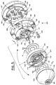
- FIGS 5-7 illustrate a preferred burner construction for use with a multi-burner, gas-supplying manifold.
- burner 100 shown in these figures can be assembled and mounted on a gas-supplying manifold with a high degree of precision.
- the burner is thus particularly well-suited for use in OVD systems wherein multiple burners are employed in the production of preforms, with each burner depositing soot on only a portion of the preform.
- precision burner 100 can be used in single burner applications, if desired.
- the preferred application of the burner is in the oxidation of halide-free, silicon-containing raw materials
- the burner can also be used with halide-containing materials.
- a gas flow pattern like that of Table 1 and a burner face configuration like that of Figure 3 will normally be used.
- the burner is used with halide-free, silicon-containing raw materials and thus has the gas flow pattern and burner face configuration of Figure 4.
- Precision burner 100 has five main components: face block 102, manifold plate 104, back block 106, fame tube 108, and burner mounting block 107.
- burner mounting block 107 is mounted on a gas-supplying manifold (not shown) by means of bolts 148 which pass through unthreaded bolt holes 146 in burner mounting block 107 and engage corresponding threaded bolt holes in the gas-supplying manifold, and then subassembly 13 is mounted on burner mounting block 107 by means of bolts 144 which pass through unthreaded bolt holes 140 in back block 106 and engage threaded bolt holes 142 in burner mounting block 107.
- bolts 148 to mount burner block 107 on the gas-supplying manifold, as opposed to flange 32 of prior art burner 10 provides improved repeatability in the mounting of an individual burner and reduced inter-burner variability in the mounting of a series of burners.
- Precision mounting of subassembly 13 on burner mounting block 107 is achieved by means of (1) alignment stud 158 which is carried by burner mounting block 107 and engages an aperture (not shown) in the back of back block 106, and (2) raised face 162 of burner mounting block 107 which is received in recess 160 of back block 106 (see Figure 7).
- Raised face 162 and recess 160 are preferably machined into their respective blocks to insure a precision fit, e.g., these features are formed by turning of the blocks.
- These blocks, as well as face block 102 and manifold plate 104 are preferably made of aluminum, which can be readily machined.
- Fume tube 108 is preferably made of stainless steel, e.g., 303 stainless steel. Other materials can, of course, be used for these components, if desired.
- O-rings 166 are used to seal gas receiving apertures 118 through 124 in burner mounting block 107 to their corresponding gas passages in back block 106.
- gas receiving apertures 118 through 124 mate with gas supply lines and gas tight fittings (not shown) provided by the gas-supplying manifold.
- gas receiving aperture 118 receives CH 4 + O 2 premix
- gas receiving aperture 120 receives OMCTS + fume O 2
- gas receiving aperture 122 receives innershield N 2
- gas receiving aperture 124 receives outershield O 2 .
- the gas flows through the burner are schematically illustrated by arrows 132 through 138, where arrow 132 represents the flow of OMCTS + fume O 2 , arrow 134 represents the flow of innershield N 2 , arrow 136 represents the flow of outershield O 2 , and arrow 138 represents the flow of CH 4 + O 2 premix.
- arrow 132 represents the flow of OMCTS + fume O 2
- arrow 134 represents the flow of innershield N 2
- arrow 136 represents the flow of outershield O 2
- arrow 138 represents the flow of CH 4 + O 2 premix.
- large gas passages are used in all parts of the burner up to the burner face to reduce the differences in pressure drops between burners.
- OMCTS + fume O 2 enters burner mounting block 107 through gas receiving aperture 120, proceeds through fume tube 108, and ultimately exits the burner ' s face through region 90.
- Fume tube 108 has a single diameter bored hole 90 for uniform pressure drop and is press fit into back block 106 until it reaches shoulder 176. In this way, a precision alignment is achieved between the fume tube and the back block.
- Burner face block 102 has a slide fit over fume tube 108 which provides alignment, as well as easy disassembly, of these components.
- the bored hole 90 of fume tube 108 preferably has a diameter of, for example, 2.2 mm.
- Orifices 168 which serve to equalize the pressure of the innershield gas, are formed as an integral part of fume tube 108. They thus form integral inner shield manifold 110 (see Figure 5). This is an important feature of precision burner 100 since it eliminates removable inner shield manifold 20 which was a source of substantial burner-to-burner variability for prior art burner 10.
- Innershield N 2 enters burner mounting block 107 through gas receiving aperture 122 ( Figure 5), proceeds through gas passage 126 in back block 106 and into central aperture 112 of that block (see arrow 134 in Figure 7), passes through integral inner shield manifold 110, and ultimately exits the burner's face through region 92.
- passage 180 proceeds radially through back block 106 and serves to connect passage 126 with central aperture 112. Passage 180 is sealed at its outer end by a Lee plug.
- Outershield O 2 enters burner mounting block 107 through gas receiving aperture 124 (Figure 5), proceeds through gas passage 128 in back block 106 and into inner annulus 114 of that block (see arrow 136 in Figure 7), passes through pressure equalizing orifices 170 of manifold plate 104, and ultimately exits the burner's face through regions 94 and 96.
- passage 182 proceeds radially through back block 106 and serves to connect passage 128 with inner annulus 114. Passage 182 is sealed at its outer end by a Lee plug.
- the CH 4 + O 2 premix enters burner mounting block 107 through gas receiving aperture 118 ( Figure 6), proceeds through gas passage 130 in back block 106 and into outer annulus 116 of that block (see arrow 138 in Figure 6), passes through pressure equalizing orifices 172 of manifold plate 104, and ultimately exits the burner's face through region 98.
- Subassembly 13 is assembled by press fitting fume tube 108 into central aperture 112 of back block 106, inserting O-rings 164 into grooves 174 of manifold plate 104, passing the manifold plate over the leading end of the fume tube and aligning bolt holes 152 in the plate with bolt holes 150 in the back block, and passing face block 102 over the leading end of the fume tube and aligning its bolt holes 154 with bolt holes 152.
- Bolts 156 are then inserted through aligned bolt holes 150, 152, and 154, and tightened to hold burner subassembly 13 together.
- thermocouple may then be mounted in bore 178 in face block 102 ( Figure 6).
- the press fitting of fume tube 108 into back block 106 has been found to result in substantially less burner-to-burner variability than that seen with the threaded approach for attaching the fume tube used in prior art burner 10.
- the rear portion of fume tube 108 comprises a central bore meeting a flat surface.
- the rear portion of fume tube 18 of prior art burner 10 had a large bore for receiving a gas fitting which tapered down to a smaller bore for carrying fume gases to the burner's face. In practice, it was found that the tapered area varied from piece-to-piece, leading to an overall increase in burner-to-burner variability.
- Manifold plate 104 includes flange 105 which serves the important function of accurately aligning face block 102 and back block 106 with one another and with the manifold plate.
- the burner-to-burner variability seen in prior art burner 10 is substantially reduced through the use of this flanged plate.
- a method of forming a silicon dioxide containing preform comprising the steps of: providing a starting member; providing a soot-producing burner having a burner face that comprises first, second, third, and fourth gas-emitting regions, the second region surrounding the first region, the third region surrounding the second region, and the fourth region surrounding the third region; providing a mixture comprising oxygen and a halide-free, silicon-containing material to the first region; providing an inert gas to the second region in an amount sufficient to inhibit soot from contacting the burner's face; providing oxygen to the third region; providing a mixture comprising oxygen and a combustible gas to the fourth region; depositing silicon dioxide containing soot on the starting member to form the preform by producing relative motion between the soot-producing burner and the starting member, wherein the third gas-emitting region comprises an inner gas-emitting subregion and an outer gas-emitting subregion, wherein the outer gas-emitting subregion of the third gas-emitting region surrounds the inner gas-
- the inventive method further comprises a method wherein each of (i) the inner gas-emitting subregion, (ii) the outer gas-emitting subregion, and (iii) the fourth gas-emitting region comprises a ring of orifices, the number of orifices of the fourth gas-emitting region being less than the number of orifices of each of the inner and outer gas-emitting subregions.
- the inventive method further comprises a method wherein each of (i) the inner gas-emitting subregion, (ii) the outer gas-emitting subregion, and (iii) the fourth gas-emitting region comprises a ring of orifices having diameters, the diameter of the orifices of the inner gas-emitting subregion being (a) substantially equal to the diameter of the orifices of the outer gas-emitting subregion and (b) greater than the diameter of the orifices of the fourth gas-emitting region.
- the inventive method further comprises a method wherein each of (i) the inner gas-emitting subregion, (ii) the outer gas-emitting subregion, and (iii) the fourth gas-emitting region comprises a ring of orifices having diameters, said rings having diameters D i , D o , and D 4 , respectively, and wherein: the difference between D 4 and D o is greater than the difference between D o and D i ; the number of orifices of the fourth gas-emitting region is less than the number of orifices of each of the inner and outer gas-emitting subregions; and the diameter of the orifices of the inner gas-emitting subregion are: substantially equal to the diameter of the orifices of the outer gas-emitting subregion; and greater than the diameter of the orifices of the fourth gas-emitting region.
- the inventive method further comprises a method wherein the soot-producing burner comprises: a burner subassembly which comprises:a back block having a plurality of gas-carrying passages, a face block having a central gas-carrying passage and a plurality of gas-carrying passages surrounding the central gas-carrying passage, a manifold plate between the back block and the face block, said manifold plate comprising a plurality of orifices for providing circumferential equalization of a pressure of a gas flowing through the plurality of gas-carrying passages surrounding the central gas-carrying passage of the face block, and means for forming an assembly of the face block, back block, and manifold plate; a burner subassembly mounting block for attachment to a gas-supplying manifold; and means for mounting the burner subassembly on the burner subassembly mounting block and preferrably wherein the gas-carrying passages upstream of the manifold plate have cross-sectional areas,
- the invention includes a soot-producing burner comprising: a burner subassembly which comprises: a back block having a plurality of gas-carrying passages, a face block having a central gas-carrying passage and a plurality of gas-carrying passages surrounding the central gas-carrying passage, a manifold plate between the back block and the face block, said manifold plate comprising a plurality of orifices for providing circumferential equalization of a pressure of gas flowing through the plurality of gas-carrying passages surrounding the central gas-carrying passage of the face block, and means for forming an assembly of the face block, back block, and manifold plate; a burner subassembly mounting block for attachment to a gas-supplying manifold; and means for mounting the burner subassembly on the burner subassembly on the burner subassembly mounting block.
- the invention further includes a soot-producing burner wherein the face block comprises a burner face having first, second, third, and fourth gas-emitting regions, the second region surrounding the first region, the third region surrounding the second region, and the fourth region surrounding the third region, the third gas-emitting region comprises an inner gas-emitting subregion and an outer gas-emitting subregion, the outer gas-emitting subregion of the third gas-emitting region surrounds the inner gas-emitting subregion of the third gas-emitting region, wherein each of (i) the inner gas-emitting subregion, (ii) the outer gas-emitting subregion, and (iii) the fourth gas-emitting region comprises a ring of orifices, said rings having diameters D i , D o , and D 4 , respectively, with the difference between D 4 and D o being greater than the difference between D o and D i .
- the face block comprises a burner face having first, second, third, and fourth gas
- the invention further includes a soot-producing burner wherein the face block comprises a burner face having first, second, third, and fourth gas-emitting regions, the second region surrounding the first region, the third region surrounding the second region, and the fourth region surrounding the third region, the third gas-emitting region comprises an inner gas-emitting subregion and an outer gas-emitting subregion, the outer gas-emitting subregion of the third gas-emitting region surrounds the inner gas-emitting subregion of the third gas-emitting region, wherein each of (i) the inner gas-emitting subregion, (ii) the outer gas-emitting subregion, and (iii) the fourth gas-emitting region comprises a ring of orifices, the number of orifices of the fourth gas-emitting region being less than the number of orifices of each of the inner and outer gas-emitting subregions.
- the face block comprises a burner face having first, second, third, and fourth gas-emitting regions
- the invention further includes a soot-producing burner wherein the face block comprises a burner face having first, second, third, and fourth gas-emitting regions, the second region surrounding the first region, the third region surrounding the second region, and the fourth region surrounding the third region, the third gas-emitting region comprises an inner gas-emitting subregion and an outer gas-emitting subregion, the outer gas-emitting subregion of the third gas-emitting region surrounds the inner gas-emitting subregion of the third gas-emitting region, wherein each of (i) the inner gas-emitting subregion, (ii) the outer gas-emitting subregion, and (iii) the fourth gas-emitting region comprises a ring of orifices having diameters, the diameter of the orifices of the inner gas-emitting subregion being (a) substantially equal to the diameter of the orifices of the outer gas-emitting subregion and (b) greater than the diameter of the orifices of the fourth gas-emit
Landscapes
- Engineering & Computer Science (AREA)
- Chemical & Material Sciences (AREA)
- Mechanical Engineering (AREA)
- General Engineering & Computer Science (AREA)
- Organic Chemistry (AREA)
- Chemical Kinetics & Catalysis (AREA)
- Combustion & Propulsion (AREA)
- Materials Engineering (AREA)
- Manufacturing & Machinery (AREA)
- General Chemical & Material Sciences (AREA)
- Environmental & Geological Engineering (AREA)
- Metallurgy (AREA)
- Plasma & Fusion (AREA)
- Physics & Mathematics (AREA)
- Geochemistry & Mineralogy (AREA)
- General Life Sciences & Earth Sciences (AREA)
- Life Sciences & Earth Sciences (AREA)
- Glass Melting And Manufacturing (AREA)
- Manufacture, Treatment Of Glass Fibers (AREA)
- Silicon Compounds (AREA)
- Pre-Mixing And Non-Premixing Gas Burner (AREA)
- Gas Burners (AREA)
Abstract
Description
| | halide containing raw material/inert |
| region | |
| 38 | |
| region | |
| 40 | combustible gas/oxygen mixture |
| region 42 | combustible gas/ |
| region | |
| 44 | oxygen |
| | halide-free, silicon-containing raw material/oxygen mixture plus, optionally, |
| region | |
| 38 | inert gas, e.g., nitrogen and/or |
| region | |
| 40 | oxygen |
| region 42 | |
| region | |
| 44 | combustible gas/oxygen mixture |
Claims (10)
- A soot-producing burner comprising:(a) a burner subassembly which comprises:a back block having a plurality of gas-carrying passages,a face block having a central gas-carrying passage and a plurality of gas-carrying passages surrounding the central gas-carrying passage,a manifold plate between the back block and the face block, said manifold plate comprising a plurality of orifices for providing circumferential equalization of a pressure of gas flowing through the plurality of gas-carrying passages surrounding the central gas-carrying passage of the face block, andmeans for forming an assembly of the face block, back block and manifold plate;(b) a burner subassembly mounting block for attachment to a gas-supplying manifold; and(c) means for mounting the burner subassembly on the burner subassembly mounting block.
- A soot-producing burner according to claim 1 comprising a fume tube which is press-fit into the back block, extends through the manifold plate, and is received in the central gas-carrying passage of the face block.
- A soot-producing burner according to claim 2 wherein the portion of the fume tube that is received in the central gas-carrying passage includes an integral manifold comprising a plurality of orifices for providing circumferential equalization of the pressure of gas flowing through said central gas-carrying passage.
- A soot-producing burner according to claim 2 wherein the fume tube has a uniform diameter central bore.
- A soot-producing burner according to claim 1 wherein the means for forming an assembly includes means for aligning the face block, back block and manifold plate.
- A soot-producing burner according to claim 5 wherein the means for aligning comprises a flange at the outer periphery of the manifold plate, wherein said flange engages both the face block and the back block.
- A soot-producing burner according to claim 1 wherein the gas-carrying passages upstream of the manifold plate have cross-sectional areas large enough to reduce a difference in a pressure drop.
- A soot-producing burner according to claim 1 wherein the soot produced therefrom is formed into an optical waveguide fiber.
- A soot-producing burner according to claim 1 wherein the face block comprises a burner face having first, second and third gas-emitting regions, the second region surrounding the first region, the third region surrounding the second region, the third gas-emitting region comprises a plurality of orifices the axis of each of which is: (i) directed towards the first region and (ii) oriented at an angle of at least about 14° with respect to a normal of the burner face.
- A soot-producing burner according to claim 1 wherein the gas-carrying passages upstream of the manifold plate have cross-sectional areas, and the orifices of the manifold plate have cross-sectional areas, wherein the cross-sectional areas of the gas-carrying passages upstream of the manifold plate are larger than the cross-sectional areas of the orifices of the manifold plate.
Priority Applications (1)
| Application Number | Priority Date | Filing Date | Title |
|---|---|---|---|
| EP02078244A EP1254867A3 (en) | 1994-12-30 | 1995-12-19 | Apparatus comprising a burner for producing silicon dioxide soot |
Applications Claiming Priority (3)
| Application Number | Priority Date | Filing Date | Title |
|---|---|---|---|
| US367047 | 1994-12-30 | ||
| US08/367,047 US5599371A (en) | 1994-12-30 | 1994-12-30 | Method of using precision burners for oxidizing halide-free, silicon-containing compounds |
| EP95944371A EP0800490B1 (en) | 1994-12-30 | 1995-12-19 | Process for producing preforms for optical fibres |
Related Parent Applications (1)
| Application Number | Title | Priority Date | Filing Date |
|---|---|---|---|
| EP95944371A Division EP0800490B1 (en) | 1994-12-30 | 1995-12-19 | Process for producing preforms for optical fibres |
Related Child Applications (1)
| Application Number | Title | Priority Date | Filing Date |
|---|---|---|---|
| EP02078244A Division EP1254867A3 (en) | 1994-12-30 | 1995-12-19 | Apparatus comprising a burner for producing silicon dioxide soot |
Publications (3)
| Publication Number | Publication Date |
|---|---|
| EP0978491A2 true EP0978491A2 (en) | 2000-02-09 |
| EP0978491A3 EP0978491A3 (en) | 2000-03-01 |
| EP0978491B1 EP0978491B1 (en) | 2003-02-26 |
Family
ID=23445723
Family Applications (3)
| Application Number | Title | Priority Date | Filing Date |
|---|---|---|---|
| EP95944371A Expired - Lifetime EP0800490B1 (en) | 1994-12-30 | 1995-12-19 | Process for producing preforms for optical fibres |
| EP99203799A Expired - Lifetime EP0978491B1 (en) | 1994-12-30 | 1995-12-19 | Precision burners for oxidizing halide-free, silicon-containing compounds |
| EP02078244A Withdrawn EP1254867A3 (en) | 1994-12-30 | 1995-12-19 | Apparatus comprising a burner for producing silicon dioxide soot |
Family Applications Before (1)
| Application Number | Title | Priority Date | Filing Date |
|---|---|---|---|
| EP95944371A Expired - Lifetime EP0800490B1 (en) | 1994-12-30 | 1995-12-19 | Process for producing preforms for optical fibres |
Family Applications After (1)
| Application Number | Title | Priority Date | Filing Date |
|---|---|---|---|
| EP02078244A Withdrawn EP1254867A3 (en) | 1994-12-30 | 1995-12-19 | Apparatus comprising a burner for producing silicon dioxide soot |
Country Status (7)
| Country | Link |
|---|---|
| US (2) | US5599371A (en) |
| EP (3) | EP0800490B1 (en) |
| JP (1) | JP3182730B2 (en) |
| AU (1) | AU689699B2 (en) |
| CA (1) | CA2208066A1 (en) |
| DE (2) | DE69529778D1 (en) |
| WO (1) | WO1996020898A2 (en) |
Cited By (4)
| Publication number | Priority date | Publication date | Assignee | Title |
|---|---|---|---|---|
| EP1193443A3 (en) * | 2000-10-02 | 2002-08-07 | Ebara Corporation | Combustion type waste gas treatment system |
| EP2236932A1 (en) * | 2009-03-17 | 2010-10-06 | Siemens Aktiengesellschaft | Burner and method for operating a burner, in particular for a gas turbine |
| US8001808B2 (en) | 2001-11-26 | 2011-08-23 | Prysmian Cavi E Sistemi Energia S.R.L. | Disassemblable burner for a vapor deposition process |
| US8516855B2 (en) | 2001-04-27 | 2013-08-27 | Prysmian Cavi E Sistemi Energia S.R.L. | Method for producing an optical fiber preform |
Families Citing this family (81)
| Publication number | Priority date | Publication date | Assignee | Title |
|---|---|---|---|---|
| US5599371A (en) * | 1994-12-30 | 1997-02-04 | Corning Incorporated | Method of using precision burners for oxidizing halide-free, silicon-containing compounds |
| DE19527451C2 (en) † | 1995-07-27 | 1998-06-04 | Heraeus Quarzglas | Process for the production of a quartz glass blank and a suitable burner |
| EP1007484A4 (en) * | 1997-07-21 | 2000-09-20 | Corning Inc | Methods and apparatus for producing low flow rates of feedstock vapors |
| GB9725878D0 (en) * | 1997-12-05 | 1998-02-04 | Imperial College | Vapour deposition |
| MXPA00006041A (en) * | 1997-12-19 | 2003-09-10 | Corning Inc | BURNER AND METHOD TO PRODUCE HOLLIN OF METAL OXIDE. |
| AU2107199A (en) * | 1998-01-08 | 1999-07-26 | Regents Of The University Of California, The | Kinesin motor modulators derived from the marine sponge (adocia) |
| US6161398A (en) * | 1998-04-09 | 2000-12-19 | Lucent Technologies, Inc. | Methods of and systems for vapor delivery control in optical preform manufacture |
| WO2000017115A1 (en) * | 1998-09-22 | 2000-03-30 | Corning Incorporated | Burners for producing boules of fused silica glass |
| US6751987B1 (en) * | 1998-09-22 | 2004-06-22 | Corning Incorporated | Burners for producing boules of fused silica glass |
| US6736633B1 (en) * | 1998-12-17 | 2004-05-18 | Corning Incorporated | Burner manifold apparatus for use in a chemical vapor deposition process |
| JP2000191337A (en) * | 1998-12-25 | 2000-07-11 | Furukawa Electric Co Ltd:The | Torch for synthesis of glass particles with hood |
| US6242136B1 (en) | 1999-02-12 | 2001-06-05 | Corning Incorporated | Vacuum ultraviolet transmitting silicon oxyfluoride lithography glass |
| US6319634B1 (en) | 1999-03-12 | 2001-11-20 | Corning Incorporated | Projection lithography photomasks and methods of making |
| US6782716B2 (en) * | 1999-02-12 | 2004-08-31 | Corning Incorporated | Vacuum ultraviolet transmitting silicon oxyfluoride lithography glass |
| US6265115B1 (en) | 1999-03-15 | 2001-07-24 | Corning Incorporated | Projection lithography photomask blanks, preforms and methods of making |
| US6783898B2 (en) | 1999-02-12 | 2004-08-31 | Corning Incorporated | Projection lithography photomask blanks, preforms and method of making |
| US6682859B2 (en) * | 1999-02-12 | 2004-01-27 | Corning Incorporated | Vacuum ultraviolet trasmitting silicon oxyfluoride lithography glass |
| WO2001005719A1 (en) * | 1999-07-19 | 2001-01-25 | Linde Gas Aktiengesellschaft | Methods for producing highly pure silicon dioxide glass and burner for carrying out this method |
| US6410192B1 (en) | 1999-11-15 | 2002-06-25 | Corning Incorporated | Photolithography method, photolithography mask blanks, and method of making |
| US6418756B1 (en) | 2000-01-28 | 2002-07-16 | Corning Incorporated | Method of making planar waveguides using low flow rates of feedstock vapors from a gas and liquid mixture |
| US6363746B1 (en) * | 2000-03-15 | 2002-04-02 | Corning Incorporated | Method and apparatus for making multi-component glass soot |
| US6374642B1 (en) * | 2000-03-15 | 2002-04-23 | Corning Incorporated | Method and apparatus for combustion-enhanced vaporization |
| US6403508B1 (en) | 2000-05-31 | 2002-06-11 | Corning Incorporated | Fused silica with constant induced absorption |
| US6988378B1 (en) | 2000-07-27 | 2006-01-24 | Corning Incorporated | Light weight porous structure |
| US6387511B1 (en) | 2000-07-27 | 2002-05-14 | Corning Incorporated | Light weight porous structure |
| AU2001268254A1 (en) * | 2000-08-15 | 2002-02-25 | Corning Incorporated | Flame hydrolysis deposition process for making integrated optical components |
| JP3865039B2 (en) * | 2000-08-18 | 2007-01-10 | 信越化学工業株式会社 | Method for producing synthetic quartz glass, synthetic quartz glass and synthetic quartz glass substrate |
| US6748768B2 (en) | 2000-12-15 | 2004-06-15 | Corning Incorporated | Apparatus and method of doping silica with fluorine during laydown |
| US6877341B1 (en) * | 2001-01-26 | 2005-04-12 | The Trustees Of Columbia University In The City Of New York | Method for controlled surface scratch removal and glass resurfacing |
| JP4742429B2 (en) * | 2001-02-19 | 2011-08-10 | 住友電気工業株式会社 | Method for producing glass particulate deposit |
| US6606883B2 (en) * | 2001-04-27 | 2003-08-19 | Corning Incorporated | Method for producing fused silica and doped fused silica glass |
| EP1284246A3 (en) * | 2001-08-09 | 2004-02-04 | Sumitomo Electric Industries, Ltd. | Method and apparatus for producing porous glass soot body |
| US6735981B2 (en) * | 2001-09-27 | 2004-05-18 | Corning Incorporated | High heat capacity burners for producing fused silica boules |
| AU2003222586A1 (en) * | 2002-03-20 | 2003-10-08 | Crystal Fibre A/S | Method of drawing microstructured glass optical fibres from a preform |
| US6910352B2 (en) * | 2002-04-24 | 2005-06-28 | Corning Incorporated | Deposition of high fluorine content silica soot |
| US8567218B2 (en) * | 2002-12-20 | 2013-10-29 | Prysmian Cavi E Sistemi Energia S.R.L. | Burner for chemical vapour deposition of glass |
| JP2004203670A (en) * | 2002-12-25 | 2004-07-22 | Shin Etsu Chem Co Ltd | Processing method of preform for optical fiber and apparatus used for the method |
| JP2004277257A (en) * | 2003-03-18 | 2004-10-07 | Sumitomo Electric Ind Ltd | Method for producing porous glass fine particle deposit and burner for synthesizing glass fine particles |
| EP1496024A1 (en) * | 2003-07-07 | 2005-01-12 | Sumitomo Electric Industries, Ltd. | Method of producing glass-particle-deposited body and glass-particle-synthesizing burner |
| KR100640405B1 (en) * | 2004-12-16 | 2006-10-31 | 삼성전자주식회사 | Burner for Fiber Optic Substrate Deposition |
| US20060162382A1 (en) * | 2004-12-30 | 2006-07-27 | Hrdina Kenneth E | Method and apparatus for producing oxide particles via flame |
| DE102005018209B4 (en) * | 2005-04-19 | 2007-08-30 | Heraeus Tenevo Gmbh | Apparatus and method for producing a quartz glass body |
| USD542375S1 (en) * | 2005-11-30 | 2007-05-08 | 3M Innovative Properites Company | Spray gun platform mounting |
| KR100762611B1 (en) * | 2006-01-10 | 2007-10-01 | 삼성전자주식회사 | Manufacturing method of optical fiber base material and manufacturing method of optical fiber using same |
| DE102007024725B4 (en) | 2007-05-25 | 2011-09-29 | Heraeus Quarzglas Gmbh & Co. Kg | Deposition burner and method for its manufacture, its use in a burner assembly and method of making a synthetic quartz glass blank using the burner assembly |
| DE102008013540A1 (en) * | 2008-03-11 | 2009-09-24 | Microjet Gmbh | Device for generating and spraying an aerosol |
| JP4818380B2 (en) * | 2009-02-27 | 2011-11-16 | 信越化学工業株式会社 | Burner for synthesizing glass fine particles and method for producing porous glass preform using the same |
| US8062733B2 (en) * | 2009-05-15 | 2011-11-22 | Corning Incorporated | Roll-to-roll glass material attributes and fingerprint |
| US8181485B2 (en) | 2009-06-19 | 2012-05-22 | Corning Incorporated | Roll-to-roll glass soot sheet sintering method and apparatus |
| US8359884B2 (en) * | 2009-07-17 | 2013-01-29 | Corning Incorporated | Roll-to-roll glass: touch-free process and multilayer approach |
| US8438876B2 (en) | 2010-03-29 | 2013-05-14 | Corning Incorporated | Method and apparatus for removing glass soot sheet from substrate |
| US8567214B2 (en) | 2010-06-28 | 2013-10-29 | Asahi Glass Company, Limited | Method for producing glass body and method for producing optical member for EUV lithography |
| JP5737070B2 (en) * | 2010-09-02 | 2015-06-17 | 信越化学工業株式会社 | Titania-doped quartz glass and method for producing the same |
| US9321669B2 (en) | 2011-08-23 | 2016-04-26 | Corning Incorporated | Thin glass sheet with tunable coefficient of thermal expansion |
| US9199870B2 (en) | 2012-05-22 | 2015-12-01 | Corning Incorporated | Electrostatic method and apparatus to form low-particulate defect thin glass sheets |
| US8857216B2 (en) * | 2012-05-31 | 2014-10-14 | Corning Incorporated | Burner modules, methods of forming glass sheets, and glass sheets formed thereby |
| US9695080B2 (en) | 2012-12-28 | 2017-07-04 | Sumitomo Electric Industries, Ltd. | Glass particle deposit producing method and glass preform producing method |
| GB2516267B (en) * | 2013-07-17 | 2016-08-17 | Edwards Ltd | Head assembly |
| US9452946B2 (en) | 2013-10-18 | 2016-09-27 | Corning Incorporated | Locally-sintered porous soot parts and methods of forming |
| JP2015093816A (en) | 2013-11-13 | 2015-05-18 | 住友電気工業株式会社 | Manufacturing method for glass fine particle deposit and manufacturing method for glass preform |
| JP5880532B2 (en) | 2013-12-12 | 2016-03-09 | 住友電気工業株式会社 | Method for producing glass particulate deposit and method for producing glass base material |
| EP3059212A1 (en) * | 2015-02-18 | 2016-08-24 | Heraeus Quarzglas GmbH & Co. KG | Method and apparatus for making silica glass from polymerisable polyalkylsiloxane with membrane filter as cleaning device |
| JP6054471B2 (en) | 2015-05-26 | 2016-12-27 | 株式会社日本製鋼所 | Atomic layer growth apparatus and exhaust layer of atomic layer growth apparatus |
| JP6054470B2 (en) | 2015-05-26 | 2016-12-27 | 株式会社日本製鋼所 | Atomic layer growth equipment |
| JP5990626B1 (en) * | 2015-05-26 | 2016-09-14 | 株式会社日本製鋼所 | Atomic layer growth equipment |
| JP2017036172A (en) * | 2015-08-07 | 2017-02-16 | 株式会社フジクラ | Manufacturing method for optical fiber preform |
| US9422187B1 (en) | 2015-08-21 | 2016-08-23 | Corning Incorporated | Laser sintering system and method for forming high purity, low roughness silica glass |
| US10562804B2 (en) | 2016-03-18 | 2020-02-18 | Corning Incorporated | Burner design for particle generation |
| JP6650820B2 (en) | 2016-04-19 | 2020-02-19 | 株式会社フジクラ | Manufacturing method of glass ingot |
| CN106430944B (en) * | 2016-11-08 | 2020-10-30 | 长飞光纤光缆股份有限公司 | Blast burner assembly for OVD process deposition optical fiber preform |
| CN109928612B (en) * | 2017-02-24 | 2021-08-06 | 天津富通集团有限公司 | A kind of manufacturing method of optical fiber preform |
| US10882777B2 (en) * | 2017-03-16 | 2021-01-05 | Corning Incorporated | Adjustable fume tube burner |
| CN107056042B (en) * | 2017-04-17 | 2023-05-09 | 江苏亨通光导新材料有限公司 | Blowtorch of optical fiber preform |
| US10844293B2 (en) * | 2017-09-25 | 2020-11-24 | Surefire Pilotless Burner Systems Llc | Sparkless igniters for heater treaters and methods for using same |
| JP6887930B2 (en) | 2017-10-05 | 2021-06-16 | 信越化学工業株式会社 | Method for manufacturing porous glass deposits for optical fibers |
| JP6756759B2 (en) * | 2018-03-22 | 2020-09-16 | 信越化学工業株式会社 | Optical fiber base material manufacturing equipment |
| US11242277B2 (en) | 2018-08-21 | 2022-02-08 | Corning Incorporated | Method of producing soot |
| JPWO2020054861A1 (en) * | 2018-09-14 | 2021-08-30 | 住友電気工業株式会社 | Method for manufacturing glass fine particle deposits and method for manufacturing glass base material |
| RU2691216C1 (en) * | 2018-09-27 | 2019-06-11 | Акционерное общество "Научно-производственное объединение Государственный оптический институт им. С.И. Вавилова" (АО "НПО ГОИ им. С.И. Вавилова") | Burner design for production of quartz glass from liquid organosilicon compounds |
| CN113439074A (en) | 2019-02-13 | 2021-09-24 | 康宁股份有限公司 | Evaporator and apparatus for forming glass optical fiber preform including the same |
| US20220098084A1 (en) * | 2020-05-20 | 2022-03-31 | Corning Incorporated | Methods for increasing deposition in a flame hydrolysis deposition process |
Family Cites Families (26)
| Publication number | Priority date | Publication date | Assignee | Title |
|---|---|---|---|---|
| US3565345A (en) * | 1968-07-11 | 1971-02-23 | Texas Instruments Inc | Production of an article of high purity metal oxide |
| US3642521A (en) * | 1969-10-27 | 1972-02-15 | Texas Instruments Inc | Production of metal oxides |
| US3698936A (en) * | 1969-12-19 | 1972-10-17 | Texas Instruments Inc | Production of very high purity metal oxide articles |
| JPS5927728B2 (en) * | 1977-08-11 | 1984-07-07 | 日本電信電話株式会社 | Manufacturing method of sooty glass rod |
| US4165223A (en) * | 1978-03-06 | 1979-08-21 | Corning Glass Works | Method of making dry optical waveguides |
| JPS5523068A (en) * | 1978-08-07 | 1980-02-19 | Nippon Telegr & Teleph Corp <Ntt> | Forming method for oxide powder layer for optical fiber |
| US4314837A (en) * | 1979-03-01 | 1982-02-09 | Corning Glass Works | Reactant delivery system method |
| US4345928A (en) * | 1979-10-09 | 1982-08-24 | Nippon Telegraph & Telephone Public Corporation | Fabrication method of single-mode optical fiber preforms |
| US4417692A (en) * | 1982-04-26 | 1983-11-29 | Western Electric Co., Inc. | Vapor-phase axial deposition torch |
| US4474593A (en) * | 1982-04-26 | 1984-10-02 | At&T Technologies Inc. | Method of fabricating a lightguide fiber |
| DE3474657D1 (en) * | 1984-01-31 | 1988-11-24 | Nippon Telegraph & Telephone | Method of fabricating optical fiber preforms |
| CA1284921C (en) * | 1984-02-27 | 1991-06-18 | Hiroyuki Suda | Method, apparatus and burner for fabricating an optical fiber preform |
| US4604118A (en) * | 1985-08-13 | 1986-08-05 | Corning Glass Works | Method for synthesizing MgO--Al2 O3 --SiO2 glasses and ceramics |
| JPS62187135A (en) * | 1986-02-12 | 1987-08-15 | Furukawa Electric Co Ltd:The | Torch for synthesizing fine glass particle |
| DE8814866U1 (en) * | 1988-11-30 | 1989-01-12 | Messer Griesheim Gmbh, 6000 Frankfurt | Connecting element for gas burner |
| DE69032175T2 (en) * | 1989-11-13 | 1998-07-09 | Corning Inc | Method and device for producing a preform with a doped metal oxide |
| US5140665A (en) | 1989-12-22 | 1992-08-18 | Corning Incorporated | Optical waveguide fiber with titania-silica outer cladding |
| CA2030748C (en) * | 1989-12-22 | 2000-08-15 | Marcella Rose Backer | Optical waveguide fiber with titania-silica outer cladding and method of manufacturing |
| US5110335A (en) * | 1990-06-25 | 1992-05-05 | At&T Bell Laboratories | Method of glass soot deposition using ultrasonic nozzle |
| US5043002A (en) * | 1990-08-16 | 1991-08-27 | Corning Incorporated | Method of making fused silica by decomposing siloxanes |
| US5116400A (en) * | 1990-09-20 | 1992-05-26 | Corning Incorporated | Apparatus for forming a porous glass preform |
| US5296012A (en) * | 1992-12-28 | 1994-03-22 | Corning Incorporated | Method of making optical waveguide preforms |
| US5702495A (en) * | 1993-02-10 | 1997-12-30 | Nikon Corporation | Silica glass member for UV-lithography, method for silica glass production, and method for silica glass member production |
| JP3007510B2 (en) * | 1993-04-27 | 2000-02-07 | 信越化学工業株式会社 | Manufacturing method of synthetic quartz glass member |
| US5356451A (en) * | 1993-12-20 | 1994-10-18 | Corning Incorporated | Method and apparatus for vaporization of liquid reactants |
| US5599371A (en) * | 1994-12-30 | 1997-02-04 | Corning Incorporated | Method of using precision burners for oxidizing halide-free, silicon-containing compounds |
-
1994
- 1994-12-30 US US08/367,047 patent/US5599371A/en not_active Expired - Fee Related
-
1995
- 1995-12-19 DE DE69529778T patent/DE69529778D1/en not_active Expired - Lifetime
- 1995-12-19 EP EP95944371A patent/EP0800490B1/en not_active Expired - Lifetime
- 1995-12-19 EP EP99203799A patent/EP0978491B1/en not_active Expired - Lifetime
- 1995-12-19 DE DE69518092T patent/DE69518092T2/en not_active Expired - Fee Related
- 1995-12-19 AU AU46439/96A patent/AU689699B2/en not_active Ceased
- 1995-12-19 JP JP52109696A patent/JP3182730B2/en not_active Expired - Fee Related
- 1995-12-19 WO PCT/US1995/016738 patent/WO1996020898A2/en not_active Ceased
- 1995-12-19 CA CA002208066A patent/CA2208066A1/en not_active Abandoned
- 1995-12-19 EP EP02078244A patent/EP1254867A3/en not_active Withdrawn
-
1996
- 1996-10-15 US US08/729,305 patent/US5922100A/en not_active Expired - Fee Related
Cited By (8)
| Publication number | Priority date | Publication date | Assignee | Title |
|---|---|---|---|---|
| EP1193443A3 (en) * | 2000-10-02 | 2002-08-07 | Ebara Corporation | Combustion type waste gas treatment system |
| US6948929B2 (en) | 2000-10-02 | 2005-09-27 | Ebara Corporation | Combustion type waste gas treatment system |
| US7607914B2 (en) | 2000-10-02 | 2009-10-27 | Ebara Corporation | Combustion type waste gas treatment system |
| US8516855B2 (en) | 2001-04-27 | 2013-08-27 | Prysmian Cavi E Sistemi Energia S.R.L. | Method for producing an optical fiber preform |
| US8001808B2 (en) | 2001-11-26 | 2011-08-23 | Prysmian Cavi E Sistemi Energia S.R.L. | Disassemblable burner for a vapor deposition process |
| EP2236932A1 (en) * | 2009-03-17 | 2010-10-06 | Siemens Aktiengesellschaft | Burner and method for operating a burner, in particular for a gas turbine |
| WO2010106034A3 (en) * | 2009-03-17 | 2011-05-26 | Siemens Aktiengesellschaft | Method for operating a burner and burner, in particular for a gas turbine |
| US9032736B2 (en) | 2009-03-17 | 2015-05-19 | Siemens Aktiengesellschaft | Method for operating a burner and burner, in particular for a gas turbine |
Also Published As
| Publication number | Publication date |
|---|---|
| DE69529778D1 (en) | 2003-04-03 |
| WO1996020898A2 (en) | 1996-07-11 |
| EP1254867A3 (en) | 2004-01-28 |
| JP3182730B2 (en) | 2001-07-03 |
| EP1254867A2 (en) | 2002-11-06 |
| EP0978491A3 (en) | 2000-03-01 |
| US5599371A (en) | 1997-02-04 |
| DE69518092D1 (en) | 2000-08-24 |
| EP0800490B1 (en) | 2000-07-19 |
| CA2208066A1 (en) | 1996-07-11 |
| AU689699B2 (en) | 1998-04-02 |
| EP0800490A2 (en) | 1997-10-15 |
| DE69518092T2 (en) | 2000-12-21 |
| EP0978491B1 (en) | 2003-02-26 |
| WO1996020898A3 (en) | 1996-12-05 |
| JPH11510778A (en) | 1999-09-21 |
| AU4643996A (en) | 1996-07-24 |
| US5922100A (en) | 1999-07-13 |
Similar Documents
| Publication | Publication Date | Title |
|---|---|---|
| AU689699B2 (en) | Precision burners for oxidizing halide-free, silicon-containing compounds | |
| US4618354A (en) | Method, apparatus and burner for fabricating an optical fiber preform | |
| FI82031C (en) | BRAENNARE FOER TILLVERKNING AV OPTISKT FIBERBASMATERIAL. | |
| EP0463783A1 (en) | Method and apparatus for making glass | |
| JP2000193215A (en) | Combustion method for manufacturing glass and metal and use thereof | |
| WO1994024483A1 (en) | Burner apparatus and method of operation thereof | |
| EP0204461B1 (en) | Burner for producing glass fine particles | |
| RU2271341C2 (en) | Multi-tubular burner and method of producing glass blank | |
| US8567218B2 (en) | Burner for chemical vapour deposition of glass | |
| WO2018142939A1 (en) | Multi-tube burner | |
| US4474593A (en) | Method of fabricating a lightguide fiber | |
| US7587914B2 (en) | Burner for manufacturing a glass optical fibre preform by vapour deposition | |
| CA1199533A (en) | Torch | |
| US6751987B1 (en) | Burners for producing boules of fused silica glass | |
| EP1140715A1 (en) | Burners for producing boules of fused silica glass | |
| US6735981B2 (en) | High heat capacity burners for producing fused silica boules | |
| JPH0324417B2 (en) | ||
| EP1343731B1 (en) | Multi-flame deposition burner and method for manufacturing optical fibre preforms | |
| JPH08303727A (en) | Quartz nozzle for fixed head burner | |
| JPS57209841A (en) | Burner for manufacturing optical fiber preform | |
| JPS62113731A (en) | Production of base material for optical fiber | |
| EP1216967A1 (en) | Method for manufacturing a glass optical fibre preform by vapour deposition | |
| JPS6259063B2 (en) | ||
| WO2002049976A1 (en) | Method and deposition burner for manufacturing optical fibre preforms | |
| EP1345860A1 (en) | Method and deposition burner for manufacturing optical fibre preforms |
Legal Events
| Date | Code | Title | Description |
|---|---|---|---|
| PUAI | Public reference made under article 153(3) epc to a published international application that has entered the european phase |
Free format text: ORIGINAL CODE: 0009012 |
|
| PUAL | Search report despatched |
Free format text: ORIGINAL CODE: 0009013 |
|
| 17P | Request for examination filed |
Effective date: 19991124 |
|
| AC | Divisional application: reference to earlier application |
Ref document number: 800490 Country of ref document: EP |
|
| AK | Designated contracting states |
Kind code of ref document: A2 Designated state(s): DE FR GB IT NL |
|
| AK | Designated contracting states |
Kind code of ref document: A3 Designated state(s): DE FR GB IT NL |
|
| RIC1 | Information provided on ipc code assigned before grant |
Free format text: 7C 03B 37/014 A, 7C 03B 19/14 B, 7F 23D 14/38 B |
|
| 17Q | First examination report despatched |
Effective date: 20001002 |
|
| AKX | Designation fees paid |
Free format text: DE FR GB IT NL |
|
| GRAG | Despatch of communication of intention to grant |
Free format text: ORIGINAL CODE: EPIDOS AGRA |
|
| GRAG | Despatch of communication of intention to grant |
Free format text: ORIGINAL CODE: EPIDOS AGRA |
|
| GRAH | Despatch of communication of intention to grant a patent |
Free format text: ORIGINAL CODE: EPIDOS IGRA |
|
| GRAH | Despatch of communication of intention to grant a patent |
Free format text: ORIGINAL CODE: EPIDOS IGRA |
|
| GRAA | (expected) grant |
Free format text: ORIGINAL CODE: 0009210 |
|
| AC | Divisional application: reference to earlier application |
Ref document number: 0800490 Country of ref document: EP Kind code of ref document: P |
|
| AK | Designated contracting states |
Designated state(s): DE FR GB IT NL |
|
| PG25 | Lapsed in a contracting state [announced via postgrant information from national office to epo] |
Ref country code: FR Free format text: LAPSE BECAUSE OF NON-PAYMENT OF DUE FEES Effective date: 20030226 |
|
| REG | Reference to a national code |
Ref country code: GB Ref legal event code: FG4D |
|
| REF | Corresponds to: |
Ref document number: 69529778 Country of ref document: DE Date of ref document: 20030403 Kind code of ref document: P |
|
| PG25 | Lapsed in a contracting state [announced via postgrant information from national office to epo] |
Ref country code: DE Free format text: LAPSE BECAUSE OF FAILURE TO SUBMIT A TRANSLATION OF THE DESCRIPTION OR TO PAY THE FEE WITHIN THE PRESCRIBED TIME-LIMIT Effective date: 20030527 |
|
| PGFP | Annual fee paid to national office [announced via postgrant information from national office to epo] |
Ref country code: GB Payment date: 20031105 Year of fee payment: 9 |
|
| PLBE | No opposition filed within time limit |
Free format text: ORIGINAL CODE: 0009261 |
|
| STAA | Information on the status of an ep patent application or granted ep patent |
Free format text: STATUS: NO OPPOSITION FILED WITHIN TIME LIMIT |
|
| EN | Fr: translation not filed | ||
| 26N | No opposition filed |
Effective date: 20031127 |
|
| PG25 | Lapsed in a contracting state [announced via postgrant information from national office to epo] |
Ref country code: NL Free format text: LAPSE BECAUSE OF NON-PAYMENT OF DUE FEES Effective date: 20040701 |
|
| NLV4 | Nl: lapsed or anulled due to non-payment of the annual fee |
Effective date: 20040701 |
|
| PG25 | Lapsed in a contracting state [announced via postgrant information from national office to epo] |
Ref country code: GB Free format text: LAPSE BECAUSE OF NON-PAYMENT OF DUE FEES Effective date: 20041219 |
|
| GBPC | Gb: european patent ceased through non-payment of renewal fee |
Effective date: 20041219 |
|
| PG25 | Lapsed in a contracting state [announced via postgrant information from national office to epo] |
Ref country code: IT Free format text: LAPSE BECAUSE OF NON-PAYMENT OF DUE FEES Effective date: 20051219 |