EP0978364A2 - Injector nozzle for an injection mould - Google Patents
Injector nozzle for an injection mould Download PDFInfo
- Publication number
- EP0978364A2 EP0978364A2 EP99890256A EP99890256A EP0978364A2 EP 0978364 A2 EP0978364 A2 EP 0978364A2 EP 99890256 A EP99890256 A EP 99890256A EP 99890256 A EP99890256 A EP 99890256A EP 0978364 A2 EP0978364 A2 EP 0978364A2
- Authority
- EP
- European Patent Office
- Prior art keywords
- injection
- nozzle
- mold
- channel
- profiles
- Prior art date
- Legal status (The legal status is an assumption and is not a legal conclusion. Google has not performed a legal analysis and makes no representation as to the accuracy of the status listed.)
- Granted
Links
- 238000002347 injection Methods 0.000 title claims abstract description 59
- 239000007924 injection Substances 0.000 title claims abstract description 59
- 239000000463 material Substances 0.000 claims abstract description 14
- 238000001746 injection moulding Methods 0.000 claims abstract description 6
- 238000004519 manufacturing process Methods 0.000 claims abstract description 6
- 229920001971 elastomer Polymers 0.000 claims abstract description 3
- 239000000806 elastomer Substances 0.000 claims abstract description 3
- 238000001816 cooling Methods 0.000 claims description 3
- 210000001520 comb Anatomy 0.000 claims description 2
- 238000009998 heat setting Methods 0.000 claims description 2
- 238000000034 method Methods 0.000 claims description 2
- 238000007711 solidification Methods 0.000 claims description 2
- 230000008023 solidification Effects 0.000 claims description 2
- 238000004073 vulcanization Methods 0.000 claims description 2
- 238000010438 heat treatment Methods 0.000 description 2
- 230000008030 elimination Effects 0.000 description 1
- 238000003379 elimination reaction Methods 0.000 description 1
- 230000017525 heat dissipation Effects 0.000 description 1
- 239000007788 liquid Substances 0.000 description 1
- 239000011344 liquid material Substances 0.000 description 1
- 229920003023 plastic Polymers 0.000 description 1
- 239000004033 plastic Substances 0.000 description 1
- 230000003716 rejuvenation Effects 0.000 description 1
Images
Classifications
-
- B—PERFORMING OPERATIONS; TRANSPORTING
- B29—WORKING OF PLASTICS; WORKING OF SUBSTANCES IN A PLASTIC STATE IN GENERAL
- B29C—SHAPING OR JOINING OF PLASTICS; SHAPING OF MATERIAL IN A PLASTIC STATE, NOT OTHERWISE PROVIDED FOR; AFTER-TREATMENT OF THE SHAPED PRODUCTS, e.g. REPAIRING
- B29C45/00—Injection moulding, i.e. forcing the required volume of moulding material through a nozzle into a closed mould; Apparatus therefor
- B29C45/17—Component parts, details or accessories; Auxiliary operations
- B29C45/20—Injection nozzles
-
- B—PERFORMING OPERATIONS; TRANSPORTING
- B29—WORKING OF PLASTICS; WORKING OF SUBSTANCES IN A PLASTIC STATE IN GENERAL
- B29C—SHAPING OR JOINING OF PLASTICS; SHAPING OF MATERIAL IN A PLASTIC STATE, NOT OTHERWISE PROVIDED FOR; AFTER-TREATMENT OF THE SHAPED PRODUCTS, e.g. REPAIRING
- B29C45/00—Injection moulding, i.e. forcing the required volume of moulding material through a nozzle into a closed mould; Apparatus therefor
- B29C45/17—Component parts, details or accessories; Auxiliary operations
- B29C45/26—Moulds
- B29C45/27—Sprue channels ; Runner channels or runner nozzles
-
- B—PERFORMING OPERATIONS; TRANSPORTING
- B29—WORKING OF PLASTICS; WORKING OF SUBSTANCES IN A PLASTIC STATE IN GENERAL
- B29K—INDEXING SCHEME ASSOCIATED WITH SUBCLASSES B29B, B29C OR B29D, RELATING TO MOULDING MATERIALS OR TO MATERIALS FOR MOULDS, REINFORCEMENTS, FILLERS OR PREFORMED PARTS, e.g. INSERTS
- B29K2021/00—Use of unspecified rubbers as moulding material
Definitions
- the invention relates to an injection nozzle for an injection mold for the production of injection molded parts from heat-setting or vulcanizing materials, in particular elastomers, which can be used for direct injection of the material with a nozzle tip protruding from a cooling jacket into an injection opening of the temperature-controlled two-part or multi-part injection mold this injection opening can be fitted, the injection channel in the nozzle tip having a cross-section which is often smaller than 1 mm 2 compared to the supply channel running through the cooled nozzle body.
- Injection nozzles of the type mentioned at the outset, as well as injection molds equipped with them and methods for producing injection molded parts, are the subject of our own EP 0 162 037 B.
- a cross section of the supply channel of less than 1 mm 2 it is practically not possible for a cross section of the supply channel of less than 1 mm 2 to have this supply channel in the Providing the end region, adjustable nozzle needle and it is therefore often sought to produce an end plug from the injection material in the injection nozzle, which closes the injection channel when the mold is opened after an injection molding process, that is to say prevents the injection material from flowing in and from the inflowing liquid in the next injection molding process.
- cooled material is ejected, which is possible because such injection machines work with pressures of the order of a few 100 bar.
- the disadvantage is that even if a taper is provided in the channel at the outlet end of the nozzle tip, the size and in particular length of this plug are not precisely defined, so that the plug may adhere to the injection molded part during the removal and be pulled out with it is, liquid material can flow in from the nozzle and the injection molded part itself becomes unusable due to the adhering stopper or at least requires reworking.
- the object of the invention is therefore that of the injectors at the beginning mentioned type of elimination of difficulties and an injection nozzle specify that fully satisfactory even at high production rates is working.
- the task is at an injection nozzle of the type mentioned solved in that in the injection channel at a distance from the outlet opening
- Profilings e.g. B. in the form of projections, undercuts, ring grooves or ring combs are provided.
- the configuration described makes it possible for the manufacturing process in the way to proceed that the nozzle tip before opening the mold to Eject the injection molded part at least into the profiles on the Solidification or vulcanization temperature of the material is heated, so that also held by the profiling during the next injection molding process graft to be ejected into the cavity from the injection material, from which the injection molded part is torn off when it is removed from the mold.
- This Approach part has a threaded end 4, with which it connects to the second part of the Nozzle body can be connected.
- the subsequent part 5 be polygonal in the manner of a mother.
Abstract
Description
Die Erfindung bezieht sich auf eine Einspritzdüse für eine Spritzgußform zum Herstellen von Spritzgußteilen aus warmverfestigenden oder vulkanisierenden Materialien, insbesondere Elastomeren, die zur unmittelbaren Einspritzung des Materials mit einer aus einem Kühlmantel vorragenden Düsenspitze in eine Einspritzöffnung der temperierten zwei- oder mehrteiligen Spritzgußform einsetzbar bzw. an diese Einspritzöffnung ansetzbar ist, wobei der Einspritzkanal in der Düsenspitze einen gegenüber dem durch den gekühlten Düsenkörper verlaufenden Zufuhrkanal vielfach kleineren Querschnitt unter 1 mm2 aufweist.The invention relates to an injection nozzle for an injection mold for the production of injection molded parts from heat-setting or vulcanizing materials, in particular elastomers, which can be used for direct injection of the material with a nozzle tip protruding from a cooling jacket into an injection opening of the temperature-controlled two-part or multi-part injection mold this injection opening can be fitted, the injection channel in the nozzle tip having a cross-section which is often smaller than 1 mm 2 compared to the supply channel running through the cooled nozzle body.
Ferner betrifft die Erfindung ein Verfahren zur Herstellung von Spritzgußteilen in einer Spritzgußform mit beheiztem Formnest und wenigstens einer erfindungsgemäßen Einspritzdüse.Furthermore, the invention relates to a method for producing injection molded parts in an injection mold with a heated mold cavity and at least one according to the invention Injector.
Einspritzdüsen der eingangs genannten Art sowie mit ihnen ausgestattete Spritzgußformen und Verfahren zur Herstellung von Spritzgußteilen sind Gegenstand der eigenen EP 0 162 037 B. Wie dort beschrieben wurde, ist es bei einem Querschnitt des Zufuhrkanales unter 1 mm2 praktisch nicht möglich, eine diesen Zufuhrkanal im Endbereich abschließende, verstellbare Düsennadel vorzusehen und es wird daher häufig angestrebt, aus dem Einspritzmaterial in der Einspritzdüse einen Endpfropfen zu erzeugen, der beim Öffnen der Form nach einem Spritzgußvorgang den Einspritzkanal verschließt, also ein Nachströmen des Einspritzmaterials verhindert und beim nächsten Spritzgußvorgang vom nachströmenden flüssigen, gekühlten Material ausgestoßen wird, was möglich ist, da bei derartigen Einspritzmaschinen mit Drücken in der Größenordnung von einigen 100 bar gearbeitet wird. Nachteilig ist, daß auch dann, wenn am Austrittsende der Düsenspitze eine Verjüngung im Kanal vorgesehen wird, Größe und insbesondere Länge dieses Pfropfens nicht genau definiert sind, so daß es vorkommen kann, daß der Pfropfen bei der Enfformung am Spritzgußteil haften bleibt und mit diesem herausgezogen wird, wobei aus der Düse flüssiges Material nachströmen kann und der Spritzgußteil selbst durch den anhaftenden Pfropfen unbrauchbar wird bzw. zumindest einer Nachbearbeitung bedarf.Injection nozzles of the type mentioned at the outset, as well as injection molds equipped with them and methods for producing injection molded parts, are the subject of our own EP 0 162 037 B. As has been described there, it is practically not possible for a cross section of the supply channel of less than 1 mm 2 to have this supply channel in the Providing the end region, adjustable nozzle needle and it is therefore often sought to produce an end plug from the injection material in the injection nozzle, which closes the injection channel when the mold is opened after an injection molding process, that is to say prevents the injection material from flowing in and from the inflowing liquid in the next injection molding process. cooled material is ejected, which is possible because such injection machines work with pressures of the order of a few 100 bar. The disadvantage is that even if a taper is provided in the channel at the outlet end of the nozzle tip, the size and in particular length of this plug are not precisely defined, so that the plug may adhere to the injection molded part during the removal and be pulled out with it is, liquid material can flow in from the nozzle and the injection molded part itself becomes unusable due to the adhering stopper or at least requires reworking.
Aus der DD 253 975 A ist es bekannt, den Düsenquerschnitt am Austrittsende einer Spritzgußmaschine für die Plastverarbeitung dadurch zu verändern, daß im Düsenkanal Vertiefungen vorgesehen werden und ein zugeordnete Vorsprünge aufweisender Düsendorn relativ zu diesen Vertiefungen verdrehbar angeordnet wird, so daß sich der Überdeckungsgrad mit den Vertiefungen und damit der Durchtrittsquerschnitt verändert.From DD 253 975 A it is known the nozzle cross section at the outlet end to change an injection molding machine for plastics processing in that Nozzle channel depressions are provided and an associated protrusion having nozzle mandrel rotatably arranged relative to these recesses is, so that the degree of coverage with the wells and thus the Passage cross section changed.
Aufgabe der Erfindung ist es demnach, die für Einspritzdüsen der eingangs genannten Art aufgezeigten Schwierigkeiten zu beseitigen und eine Einspritzdüse anzugeben, die auch bei hohen Produktionsraten voll zufriedenstellend arbeitet.The object of the invention is therefore that of the injectors at the beginning mentioned type of elimination of difficulties and an injection nozzle specify that fully satisfactory even at high production rates is working.
Die gestellte Aufgabe wird bei einer Einspritzdüse der eingangs genannten Art dadurch gelöst, daß im Einspritzkanal mit Abstand von der Austrittsöffnung Profilierungen, z. B. in Form von Vorsprüngen, Hinterschneidungen, Ringnuten oder Ringkämmen vorgesehen sind.The task is at an injection nozzle of the type mentioned solved in that in the injection channel at a distance from the outlet opening Profilings, e.g. B. in the form of projections, undercuts, ring grooves or ring combs are provided.
Die beschriebene Ausgestaltung ermöglicht es, beim Herstellungsverfahren in der Weise vorzugehen, daß die Düsenspitze vor dem Öffnen der Form zum Auswerfen des Spritzgußteiles wenigstens bis in die Profilierungen auf die Verfestigungs- bzw. Vulkanisationstemperatur des Materials erwärmt wird, so daß ein auch von der Profilierung gehaltener, beim nächsten Spritzgußvorgang in das Formnest auszustoßender Pfropfen aus dem Einspritzmaterial entsteht, von dem der Spritzgußteil bei seiner Enfformung abgerissen wird. The configuration described makes it possible for the manufacturing process in the way to proceed that the nozzle tip before opening the mold to Eject the injection molded part at least into the profiles on the Solidification or vulcanization temperature of the material is heated, so that also held by the profiling during the next injection molding process graft to be ejected into the cavity from the injection material, from which the injection molded part is torn off when it is removed from the mold.
Größe und Länge des Pfropfens sind durch die erfindungsgemäße Ausgestaltung eindeutig definiert und der Pfropfen erhält an der Profilierung eine zusätzliche Unterstützung, durch die verhindert wird, daß bei seinem nun genau an der Anspritzstelle am Formling erfolgenden Abtrennen vom Spritzgußteil ein Herausziehen mit diesem Spritzgußteil vor sich gehen kann. Praktisch wird in den meisten Fällen die Erwärmung der Düsenspitze durch Wärmeleitung aus der Form und zum Teil auch über das in der Form aushärtende bzw. vulkanisierende Material erfolgen. Bringt man die Profilierung, wie beschrieben, im Bereich der Düsenspitze an, so verringert sich im Profilierungsbereich der die Wärmeleitung bewirkende Querschnitt der Düsenspitze selbst, so daß deren Erwärmung bis zum Austrittsende begünstigt, die Wärmeableitung zum gekühlten anschließenden Düsenkörper aber verringert wird.The size and length of the plug are due to the design according to the invention clearly defined and the stopper receives an additional profile Support that prevents his from being exactly at the Injection point on the molded part from the injection molded part a pull out can go with this injection molded part. Practical is in the most cases the heating of the nozzle tip by heat conduction from the Form and partly also in the form of curing or vulcanizing Material. Bring the profiling, as described, in the area of Nozzle tip, the heat conduction in the profiling area is reduced effecting cross section of the nozzle tip itself, so that its heating up favored to the outlet end, the heat dissipation to the cooled subsequent Nozzle body is reduced.
Weitere Einzelheiten und Vorteile des Erfindungsgegenstandes entnimmt man der nachfolgenden Zeichnungsbeschreibung. In der Zeichnung ist der Erfindungsgegenstand beispielsweise veranschaulicht. Es zeigen
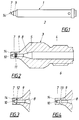
- Fig. 1
- eine Einspritzdüse in Seitenansicht,
- Fig. 2
- einen Längsschnitt durch einen die Düsenspitze enthaltenden Ansatzteil der Einspritzdüse und die
- Fig. 3 und 4
- Ausführungsvarianten mit möglichen Profilierungen im Zuge des Ein-spritzkanales.
- Fig. 1
- an injector in side view,
- Fig. 2
- a longitudinal section through a part of the injection nozzle containing the tip and the
- 3 and 4
- Design variants with possible profiles in the course of the injection channel.
Die Einspritzdüse 1 nach Fig. 1 besitzt einen innerhalb eines Kühlmantels 2
untergebrachten Düsenkörper, der zweiteilig ausgeführt ist, um beim Verschleiß
eine Auswechslung des Ansatzteiles 3 nach Fig. 2 zu ermöglichen. Dieser
Ansatzteil besitzt ein Gewindeende 4, mit dem er an den zweiten Teil des
Düsenkörpers anschließbar ist. Zur Erleichterung der Handhabung kann der
anschließende Teil 5 nach Art einer Mutter mehreckig ausgebildet sein. Durch
den Düsenkörper führt ein Zufuhrkanal 6 für das Einspritzmaterial, der sich
gegen eine Düsenspitze 7 zu bei 8 konisch zu einem Einspritzkanal 9 verengt,
der seinerseits noch einmal gegen eine Austrittsöffnung 10 abgesetzt bzw.
verjüngt ist. 1 has one within a
Mit Abstand von der Austrittsöffnung sind im Einspritzkanal 9 Profilierungen vorgesehen,
die nach Fig. 2 aus zwei von einem Ringkamm getrennten Ringnuten
11, nach Fig. 3 aus einer schräg eingeschnittenen Ringnut 12 und nach Fig. 3
aus einer anders profilierten Ringnut 13 bestehen können. Es sind auch Kombinationen
der beschriebenen Profilierungen möglich, wobei nach einer weiteren
Variante der innere Teil des Einspritzkanales über einen größeren Teil seiner
Länge Feinprofilierungen aufweisen kann. Auch die Profilierungen 11 - 13 nach
den Ausführungsbeispielen können wesentlich geringere Tiefen als dargestellt
haben.At a distance from the outlet opening, 9 profiles are provided in the injection channel,
2 of two ring grooves separated by a
Die Düsenspitze 7 wird jeweils mit ihrem Ende 14 in die Einspritzöffnung einer
Spritzgußform eingesetzt. Nach einer bevorzugten Ausführung bildet die Düsenspitze
in der eingesetzten Stellung selbst einen Teil der Wandung des Formnestes.
Es ist aber auch möglich, am Formnest eine durch einen Bereich relativ
geringer Wandstärke der Form führende Einspritzöffnung z. B. mit einem der
Öffnung 10 entsprechenden Durchmesser vorzusehen und die Düsenspitze 7 mit
fluchtender Öffnung 10 dort anzusetzen.The
Claims (2)
Applications Claiming Priority (2)
| Application Number | Priority Date | Filing Date | Title |
|---|---|---|---|
| AT0135498A AT406564B (en) | 1998-08-06 | 1998-08-06 | INJECTION NOZZLE FOR AN INJECTION MOLD |
| AT135498 | 1998-08-06 |
Publications (3)
| Publication Number | Publication Date |
|---|---|
| EP0978364A2 true EP0978364A2 (en) | 2000-02-09 |
| EP0978364A3 EP0978364A3 (en) | 2000-09-20 |
| EP0978364B1 EP0978364B1 (en) | 2002-09-25 |
Family
ID=3512081
Family Applications (1)
| Application Number | Title | Priority Date | Filing Date |
|---|---|---|---|
| EP99890256A Expired - Lifetime EP0978364B1 (en) | 1998-08-06 | 1999-08-04 | Injector nozzle for an injection mould |
Country Status (3)
| Country | Link |
|---|---|
| EP (1) | EP0978364B1 (en) |
| AT (2) | AT406564B (en) |
| DE (1) | DE59902821D1 (en) |
Cited By (1)
| Publication number | Priority date | Publication date | Assignee | Title |
|---|---|---|---|---|
| AU2008323609B2 (en) * | 2007-11-12 | 2014-07-31 | Romar Engineering Pty Ltd | An injector nozzle and method of manufacture |
Families Citing this family (1)
| Publication number | Priority date | Publication date | Assignee | Title |
|---|---|---|---|---|
| DE10301241B3 (en) * | 2003-01-15 | 2004-07-08 | Rothenaicher, Otto, Dipl.-Ing. (Fh) | Cold-channel pressure injection molding nozzle for thermally-cross linked elastomers, is longitudinally-split, clamped and has slotted outlet |
Citations (4)
| Publication number | Priority date | Publication date | Assignee | Title |
|---|---|---|---|---|
| JPS5845037A (en) * | 1981-09-10 | 1983-03-16 | Toshiba Mach Co Ltd | Runnerless injection molding method |
| EP0162037B1 (en) * | 1984-03-21 | 1989-04-26 | Franz Sterner | Method for producing injection-moulded parts, and injection mould for carrying out this method |
| JPH01249417A (en) * | 1988-03-31 | 1989-10-04 | Niigata Eng Co Ltd | Nozzle for injection molder |
| WO1997027988A1 (en) * | 1996-02-01 | 1997-08-07 | Aga Aktiebolag | An injection moulding process |
Family Cites Families (1)
| Publication number | Priority date | Publication date | Assignee | Title |
|---|---|---|---|---|
| DD253975A1 (en) * | 1986-11-27 | 1988-02-10 | Umform & Plastverarb Fz | DEVICE FOR CHROMINOUS ADJUSTMENT OF THE DUESEN CROSS SECTION OF INJECTION MOLDING MACHINES |
-
1998
- 1998-08-06 AT AT0135498A patent/AT406564B/en not_active IP Right Cessation
-
1999
- 1999-08-04 AT AT99890256T patent/ATE224799T1/en active
- 1999-08-04 EP EP99890256A patent/EP0978364B1/en not_active Expired - Lifetime
- 1999-08-04 DE DE59902821T patent/DE59902821D1/en not_active Expired - Lifetime
Patent Citations (4)
| Publication number | Priority date | Publication date | Assignee | Title |
|---|---|---|---|---|
| JPS5845037A (en) * | 1981-09-10 | 1983-03-16 | Toshiba Mach Co Ltd | Runnerless injection molding method |
| EP0162037B1 (en) * | 1984-03-21 | 1989-04-26 | Franz Sterner | Method for producing injection-moulded parts, and injection mould for carrying out this method |
| JPH01249417A (en) * | 1988-03-31 | 1989-10-04 | Niigata Eng Co Ltd | Nozzle for injection molder |
| WO1997027988A1 (en) * | 1996-02-01 | 1997-08-07 | Aga Aktiebolag | An injection moulding process |
Non-Patent Citations (2)
| Title |
|---|
| PATENT ABSTRACTS OF JAPAN vol. 007, no. 126 (M-219), 31. Mai 1983 (1983-05-31) & JP 58 045037 A (TOSHIBA KIKAI KK), 16. März 1983 (1983-03-16) * |
| PATENT ABSTRACTS OF JAPAN vol. 013, no. 593 (M-914), 27. Dezember 1989 (1989-12-27) & JP 01 249417 A (NIIGATA ENG CO LTD), 4. Oktober 1989 (1989-10-04) * |
Cited By (1)
| Publication number | Priority date | Publication date | Assignee | Title |
|---|---|---|---|---|
| AU2008323609B2 (en) * | 2007-11-12 | 2014-07-31 | Romar Engineering Pty Ltd | An injector nozzle and method of manufacture |
Also Published As
| Publication number | Publication date |
|---|---|
| EP0978364A3 (en) | 2000-09-20 |
| ATA135498A (en) | 1999-11-15 |
| EP0978364B1 (en) | 2002-09-25 |
| DE59902821D1 (en) | 2002-10-31 |
| AT406564B (en) | 2000-06-26 |
| ATE224799T1 (en) | 2002-10-15 |
Similar Documents
| Publication | Publication Date | Title |
|---|---|---|
| EP0162037B1 (en) | Method for producing injection-moulded parts, and injection mould for carrying out this method | |
| DE60316444T2 (en) | VALVE NODE GUIDANCE AND ALIGNMENT SYSTEM FOR A HOT CHANNEL IN AN INJECTION MOLDING DEVICE | |
| EP0393315B2 (en) | Method for injection moulding fluid-filled plastic articles and apparatus for carrying out the method | |
| DE19652047B4 (en) | Hot runner nozzle with a nozzle front part made of a carbide alloy | |
| EP2286974B1 (en) | Forming device and method for removing an object | |
| WO1991006413A1 (en) | Electrically heated nozzle for injection moulding machines, hot runner moulds or the like | |
| DE102005050161A1 (en) | Injection molding apparatus for producing plastic parts, has nozzle(s) having nozzle tip with rounded terminal end, nozzle melt channel with discharge opening for discharging melt flow from the nozzle melt channel towards gate | |
| EP2015916A1 (en) | Two-piece bottom insert | |
| EP0668140B1 (en) | Method of manufacturing toothbrushes | |
| EP0978364B1 (en) | Injector nozzle for an injection mould | |
| EP1687127B1 (en) | Mold cavity structure | |
| DE4014244C2 (en) | ||
| EP2015917A1 (en) | Bottom insert with heat insulation | |
| DE3711079A1 (en) | Process and device for injection-moulding moulded parts from at least two different plastic components | |
| EP0710535A1 (en) | Injection mould | |
| EP1410891A1 (en) | Cold runner shut-off nozzle for the injection molding of elastomers | |
| DE19703291C1 (en) | Multi-component pressure injection moulding e.g. of strong lightweight hollow object with tough core and thin outer coating | |
| DE4331207A1 (en) | Process and apparatus for plasticising and injection-moulding | |
| EP1084018B1 (en) | Device and method for precision casting of wax moulded parts | |
| DE3545002A1 (en) | Process for injection moulding plastic parts from thermosets | |
| EP1338398A1 (en) | Apparatus for multicomponent moulding of plastic parts | |
| DE19503073A1 (en) | Low waste nozzle for injecting liq. or semi-liq. plastics | |
| DE3927122C2 (en) | ||
| DE19848508B4 (en) | hot runner nozzle | |
| DE102007024744A1 (en) | Injection molding tool for plastic bottle with screw neck has transposed water cooling ducts |
Legal Events
| Date | Code | Title | Description |
|---|---|---|---|
| PUAI | Public reference made under article 153(3) epc to a published international application that has entered the european phase |
Free format text: ORIGINAL CODE: 0009012 |
|
| AK | Designated contracting states |
Kind code of ref document: A2 Designated state(s): AT CH DE FR GB IT LI |
|
| AX | Request for extension of the european patent |
Free format text: AL;LT;LV;MK;RO;SI |
|
| PUAL | Search report despatched |
Free format text: ORIGINAL CODE: 0009013 |
|
| AK | Designated contracting states |
Kind code of ref document: A3 Designated state(s): AT BE CH CY DE DK ES FI FR GB GR IE IT LI LU MC NL PT SE |
|
| AX | Request for extension of the european patent |
Free format text: AL;LT;LV;MK;RO;SI |
|
| RIC1 | Information provided on ipc code assigned before grant |
Free format text: 7B 29C 45/00 A, 7B 29C 45/20 B, 7B 29C 45/76 B, 7B 29C 45/27 B |
|
| 17P | Request for examination filed |
Effective date: 20010108 |
|
| AKX | Designation fees paid |
Free format text: AT CH DE FR GB IT LI |
|
| 17Q | First examination report despatched |
Effective date: 20011130 |
|
| GRAG | Despatch of communication of intention to grant |
Free format text: ORIGINAL CODE: EPIDOS AGRA |
|
| GRAG | Despatch of communication of intention to grant |
Free format text: ORIGINAL CODE: EPIDOS AGRA |
|
| GRAH | Despatch of communication of intention to grant a patent |
Free format text: ORIGINAL CODE: EPIDOS IGRA |
|
| GRAH | Despatch of communication of intention to grant a patent |
Free format text: ORIGINAL CODE: EPIDOS IGRA |
|
| GRAA | (expected) grant |
Free format text: ORIGINAL CODE: 0009210 |
|
| AK | Designated contracting states |
Kind code of ref document: B1 Designated state(s): AT CH DE FR GB IT LI |
|
| PG25 | Lapsed in a contracting state [announced via postgrant information from national office to epo] |
Ref country code: IT Free format text: LAPSE BECAUSE OF FAILURE TO SUBMIT A TRANSLATION OF THE DESCRIPTION OR TO PAY THE FEE WITHIN THE PRESCRIBED TIME-LIMIT;WARNING: LAPSES OF ITALIAN PATENTS WITH EFFECTIVE DATE BEFORE 2007 MAY HAVE OCCURRED AT ANY TIME BEFORE 2007. THE CORRECT EFFECTIVE DATE MAY BE DIFFERENT FROM THE ONE RECORDED. Effective date: 20020925 Ref country code: GB Free format text: LAPSE BECAUSE OF FAILURE TO SUBMIT A TRANSLATION OF THE DESCRIPTION OR TO PAY THE FEE WITHIN THE PRESCRIBED TIME-LIMIT Effective date: 20020925 Ref country code: FR Free format text: LAPSE BECAUSE OF FAILURE TO SUBMIT A TRANSLATION OF THE DESCRIPTION OR TO PAY THE FEE WITHIN THE PRESCRIBED TIME-LIMIT Effective date: 20020925 |
|
| REF | Corresponds to: |
Ref document number: 224799 Country of ref document: AT Date of ref document: 20021015 Kind code of ref document: T |
|
| REG | Reference to a national code |
Ref country code: GB Ref legal event code: FG4D Free format text: NOT ENGLISH |
|
| REG | Reference to a national code |
Ref country code: CH Ref legal event code: EP |
|
| REF | Corresponds to: |
Ref document number: 59902821 Country of ref document: DE Date of ref document: 20021031 |
|
| REG | Reference to a national code |
Ref country code: CH Ref legal event code: NV Representative=s name: E. BLUM & CO. PATENTANWAELTE |
|
| GBV | Gb: ep patent (uk) treated as always having been void in accordance with gb section 77(7)/1977 [no translation filed] |
Effective date: 20020925 |
|
| EN | Fr: translation not filed | ||
| PLBE | No opposition filed within time limit |
Free format text: ORIGINAL CODE: 0009261 |
|
| STAA | Information on the status of an ep patent application or granted ep patent |
Free format text: STATUS: NO OPPOSITION FILED WITHIN TIME LIMIT |
|
| 26N | No opposition filed |
Effective date: 20030626 |
|
| REG | Reference to a national code |
Ref country code: CH Ref legal event code: PFA Owner name: STERNER, FRANZ Free format text: STERNER, FRANZ#PILGRAMSTRASSE 1#4614 MARCHTRENK (AT) -TRANSFER TO- STERNER, FRANZ#PILGRAMSTRASSE 1#4614 MARCHTRENK (AT) |
|
| REG | Reference to a national code |
Ref country code: AT Ref legal event code: PC Ref document number: 224799 Country of ref document: AT Kind code of ref document: T Owner name: BETA BERATUNGS- UND BETEILIGUNGS-GMBH, AT Effective date: 20121204 |
|
| PGFP | Annual fee paid to national office [announced via postgrant information from national office to epo] |
Ref country code: AT Payment date: 20180820 Year of fee payment: 20 Ref country code: CH Payment date: 20180824 Year of fee payment: 20 |
|
| PGFP | Annual fee paid to national office [announced via postgrant information from national office to epo] |
Ref country code: DE Payment date: 20181031 Year of fee payment: 20 |
|
| REG | Reference to a national code |
Ref country code: DE Ref legal event code: R071 Ref document number: 59902821 Country of ref document: DE |
|
| REG | Reference to a national code |
Ref country code: CH Ref legal event code: PL |
|
| REG | Reference to a national code |
Ref country code: AT Ref legal event code: MK07 Ref document number: 224799 Country of ref document: AT Kind code of ref document: T Effective date: 20190804 |