EP0977321A1 - Two-part electrical connector housing - Google Patents
Two-part electrical connector housing Download PDFInfo
- Publication number
- EP0977321A1 EP0977321A1 EP99202103A EP99202103A EP0977321A1 EP 0977321 A1 EP0977321 A1 EP 0977321A1 EP 99202103 A EP99202103 A EP 99202103A EP 99202103 A EP99202103 A EP 99202103A EP 0977321 A1 EP0977321 A1 EP 0977321A1
- Authority
- EP
- European Patent Office
- Prior art keywords
- tab
- wall
- rigid arm
- opening
- parts
- Prior art date
- Legal status (The legal status is an assumption and is not a legal conclusion. Google has not performed a legal analysis and makes no representation as to the accuracy of the status listed.)
- Withdrawn
Links
Images


Classifications
-
- H—ELECTRICITY
- H01—ELECTRIC ELEMENTS
- H01R—ELECTRICALLY-CONDUCTIVE CONNECTIONS; STRUCTURAL ASSOCIATIONS OF A PLURALITY OF MUTUALLY-INSULATED ELECTRICAL CONNECTING ELEMENTS; COUPLING DEVICES; CURRENT COLLECTORS
- H01R13/00—Details of coupling devices of the kinds covered by groups H01R12/70 or H01R24/00 - H01R33/00
- H01R13/46—Bases; Cases
- H01R13/502—Bases; Cases composed of different pieces
- H01R13/506—Bases; Cases composed of different pieces assembled by snap action of the parts
Definitions
- the present invention relates to a two-part housing for an electrical connector.
- a two-part housing for an electrical connector in which the two parts of the housing make a sliding snap fit together.
- One of the parts of the housing has a substantially rigid arm with a latching tab.
- the other part has a corresponding opening adjacent a wall with a corresponding latching tab.
- the arm is pushed through the opening and the tab on the arm makes a snap fit behind the tab on the wall.
- the tabs may fail to latch together.
- a two-part housing in accordance with the present invention for an electrical connector comprises a first part having a surface with an opening therethrough, and a second part having a substantially rigid arm extending from a surface of the second part, the rigid arm being capable of passing through the opening to latch the first and second parts together;
- the rigid arm having a first side and a second side, the first side having a first tab with a first surface directed towards the surface of the second part and a second surface directed away from the surface of the second part, the second surface being at an angle to the first side;
- the first part having a wall adjacent the opening and extending away from the surface, the wall having a first tab with a first surface directed towards the opening and a second surface directed away from the opening, the first surface being at an angle to the wall;
- the first surface of the first tab on the wall engaging the second surface on the first tab on the rigid arm during latching of the first and second parts, and the second surface of the first tab on the wall being positioned adjacent the first surface on the first tab on the rigid arm
- the resilient arm ensures that the rigid arm is biased towards the wall to maintain the latch engagement between the first tabs.
- the two-part housing 10 in accordance with the present invention comprises a first part 12 and a second part 14 which makes a snap fit with the first part by one (as shown) or more latching means 16 (described in more detail below).
- the housing 10 is part of an electrical connector and the first part 12 typically houses electrical terminals and components (not shown for the sake of clarity), and the second part 14 (when latched to the first part) retains the terminals and components in the first part.
- the second part 14 typically has apertures 18 therein through which corresponding electrical terminals may extend to make an electrical connection with terminals inside the housing 10.
- the latching means 16 includes a substantially rigid arm 20 which is attached to, preferably integrally moulded with, a surface 62 of the second part 14 of the housing 10 and extends away from the surface in a direction A.
- the arm 20 has a first side 22 and an opposed second side 24.
- a first tab 26 and a second tab 28 are formed on the first side 22 of the arm 20 and positioned substantially adjacent one another in a direction substantially perpendicular to direction A.
- the first tab 26 has a first surface 30 facing the surface 62 of the second part 14 and a second surface 32 facing away from the surface of the second part.
- the first and second surfaces 30,32 are preferably at an acute angle to the first side 22 of the arm 20 such that the first tab 26 has a substantially trapezoidal shape.
- the second tab 28 has a first surface 34 facing the surface 62 of the second part 14 and a second surface 36 facing away from the surface of the second part.
- the first surface 34 is preferably substantially perpendicular to the first side 22 of the arm 20, and the second surface 36 is preferably at an acute angle to the first side.
- the first and second tabs 26,28 may be integrally connected.
- the latching means 16 further includes an opening 38 formed in a surface 40 of the first part 12 of the housing 10.
- a wall 42 is integrally formed with the first part 12 and is positioned adjacent to, and internally of, the opening 38.
- the wall 42 extends away from the opening 38 in a direction B substantially perpendicular to the surface 40.
- a first tab 44 and a second tab 46 are formed on the wall 42 with the second tab positioned closer to the opening 38 than the first tab in the direction B, and offset from one another in a direction substantially perpendicular to direction B.
- the first tab 44 has a first surface 48 facing the opening 38 and a second surface 50 facing away from the opening.
- the first and second surfaces 48,50 are preferably at an acute angle to the wall 42 such that the first tab 44 has a substantially trapezoidal shape.
- the second tab 46 has a first surface 52 facing the opening 38 and a second surface 54 facing away from the opening 38.
- the first surface 52 is preferably at an acute angle to the wall 42
- the second surface 54 is
- the latching means 16 still further includes a resilient arm 56 positioned on the opposite side of the opening 38 to the wall 42, and preferably integrally moulded with the first part 12 of the housing 10.
- the resilient arm 56 overlies the first and second tabs 44,46 on the wall 42, and has a fixed end 58 adjacent the opening 38 and a free end 60 which is normally closer to the wall than the fixed end.
- the minimum gap between the free end 60 of the resilient arm 56, or any other portion of the resilient arm, and the first tab 44 is substantially the same as or less than the distance between the first and second sides 22,24 of the rigid arm 20.
- the latching means 16 operates by pushing the second part 14 of the housing 10 towards the first part 12 such that the rigid arm 20 passes through the opening 38 as shown in Figure 2, and directions A and B are substantially aligned.
- first and second parts 12,14 towards one another initially causes the second surface 32 of the first tab 26 on the rigid arm 20 to engage the first surface 48 of the first tab 44 on the wall 42, then slide relative to one another until the first tabs pass one another and make a snap fit.
- first surface 30 of the first tab 26 on the rigid arm 20 is positioned adjacent the second surface 50 of the first tab 44 on the wall 42, and the resilient arm 56 continues to engage the second side 24 of the rigid arm 20 to bias the rigid arm towards the wall to exert a retaining force on the rigid arm.
- the presence of the resilient arm 56 ensures that the first and second parts 12,14 of the housing 10 remain accurately aligned (that is, directions A and B remain aligned) during and after the latching process, and retain the two parts in latching engagement.
- the first surface 30 of the first tab 26 on the rigid arm 20 and the second surface 50 of the first tab 44 on the wall 42 being at an angle is optional and may be replaced by perpendicular surfaces.
- the angled surfaces 30,50 allow easier disassembly from the final latched position shown in Figure 4 to the initial latched position shown in Figure 3.
- the presence of the second tabs 28,46 on the rigid arm 20 and the wall 42 is optional and may be omitted.
Abstract
Description
- The present invention relates to a two-part housing for an electrical connector.
- It is known to provide a two-part housing for an electrical connector in which the two parts of the housing make a sliding snap fit together. One of the parts of the housing has a substantially rigid arm with a latching tab. The other part has a corresponding opening adjacent a wall with a corresponding latching tab. To latch the two parts of the housing together, the arm is pushed through the opening and the tab on the arm makes a snap fit behind the tab on the wall. However, if the two parts are not accurately positioned relative to one another, for example, when the arm is at an angle to the wall, the tabs may fail to latch together.
- It is an object of the present invention to overcome the above mentioned disadvantage.
- A two-part housing in accordance with the present invention for an electrical connector comprises a first part having a surface with an opening therethrough, and a second part having a substantially rigid arm extending from a surface of the second part, the rigid arm being capable of passing through the opening to latch the first and second parts together; the rigid arm having a first side and a second side, the first side having a first tab with a first surface directed towards the surface of the second part and a second surface directed away from the surface of the second part, the second surface being at an angle to the first side; the first part having a wall adjacent the opening and extending away from the surface, the wall having a first tab with a first surface directed towards the opening and a second surface directed away from the opening, the first surface being at an angle to the wall; the first surface of the first tab on the wall engaging the second surface on the first tab on the rigid arm during latching of the first and second parts, and the second surface of the first tab on the wall being positioned adjacent the first surface on the first tab on the rigid arm after latching of the first and second parts; and a resilient arm positioned on the opposite side of the opening to the wall and overlying the first tab on the wall, the resilient arm engaging the second side of the rigid arm during and after latching of the first and second parts to bias the first side of the rigid arm towards the wall.
- The resilient arm ensures that the rigid arm is biased towards the wall to maintain the latch engagement between the first tabs.
- The present invention will now be described, by way of example, with reference to the accompanying drawings, in which:-
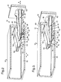
- Figure 1 is an exploded view of a two-part housing in accordance with the present invention;
- Figure 2 is a cross-sectional view of the latching means on the two parts of the housing of Figure 1 prior to latching;
- Figure 3 is a cross-sectional view similar to Figure 2 with the two parts of the housing in an initial latched positioned; and
- Figure 4 is a cross-sectional view similar to Figure 2 with the two parts of the housing in a final latched position.
-
- Referring to Figure 1, the two-
part housing 10 in accordance with the present invention comprises afirst part 12 and asecond part 14 which makes a snap fit with the first part by one (as shown) or more latching means 16 (described in more detail below). Thehousing 10 is part of an electrical connector and thefirst part 12 typically houses electrical terminals and components (not shown for the sake of clarity), and the second part 14 (when latched to the first part) retains the terminals and components in the first part. Thesecond part 14 typically hasapertures 18 therein through which corresponding electrical terminals may extend to make an electrical connection with terminals inside thehousing 10. - Referring to Figure 2 to 4, the latching means 16 includes a substantially
rigid arm 20 which is attached to, preferably integrally moulded with, asurface 62 of thesecond part 14 of thehousing 10 and extends away from the surface in a direction A. Thearm 20 has afirst side 22 and an opposedsecond side 24. Afirst tab 26 and asecond tab 28 are formed on thefirst side 22 of thearm 20 and positioned substantially adjacent one another in a direction substantially perpendicular to direction A. Thefirst tab 26 has afirst surface 30 facing thesurface 62 of thesecond part 14 and asecond surface 32 facing away from the surface of the second part. The first andsecond surfaces first side 22 of thearm 20 such that thefirst tab 26 has a substantially trapezoidal shape. Thesecond tab 28 has afirst surface 34 facing thesurface 62 of thesecond part 14 and asecond surface 36 facing away from the surface of the second part. Thefirst surface 34 is preferably substantially perpendicular to thefirst side 22 of thearm 20, and thesecond surface 36 is preferably at an acute angle to the first side. The first andsecond tabs - The latching means 16 further includes an
opening 38 formed in asurface 40 of thefirst part 12 of thehousing 10. Awall 42 is integrally formed with thefirst part 12 and is positioned adjacent to, and internally of, the opening 38. Thewall 42 extends away from theopening 38 in a direction B substantially perpendicular to thesurface 40. Afirst tab 44 and asecond tab 46 are formed on thewall 42 with the second tab positioned closer to theopening 38 than the first tab in the direction B, and offset from one another in a direction substantially perpendicular to direction B. Thefirst tab 44 has afirst surface 48 facing the opening 38 and asecond surface 50 facing away from the opening. The first andsecond surfaces wall 42 such that thefirst tab 44 has a substantially trapezoidal shape. Thesecond tab 46 has afirst surface 52 facing the opening 38 and asecond surface 54 facing away from theopening 38. Thefirst surface 52 is preferably at an acute angle to thewall 42, and thesecond surface 54 is preferably substantially perpendicular to the wall. - The latching means 16 still further includes a
resilient arm 56 positioned on the opposite side of the opening 38 to thewall 42, and preferably integrally moulded with thefirst part 12 of thehousing 10. Theresilient arm 56 overlies the first andsecond tabs wall 42, and has a fixedend 58 adjacent the opening 38 and afree end 60 which is normally closer to the wall than the fixed end. The minimum gap between thefree end 60 of theresilient arm 56, or any other portion of the resilient arm, and thefirst tab 44 is substantially the same as or less than the distance between the first andsecond sides rigid arm 20. - The latching means 16 operates by pushing the
second part 14 of thehousing 10 towards thefirst part 12 such that therigid arm 20 passes through theopening 38 as shown in Figure 2, and directions A and B are substantially aligned. - Further relative movement of the first and
second parts second surface 36 of thesecond tab 28 on therigid arm 20 to engage thefirst surface 52 of thesecond tab 46 on thewall 42, then slide relative to one another until the second tabs pass one another and make a snap fit. In this position, as shown in Figure 3, thefirst surface 34 of thesecond tab 28 on therigid arm 20 is positioned adjacent thesecond surface 54 of thesecond tab 46 on thewall 42, and theresilient arm 56 engages thesecond side 24 of therigid arm 20 to bias the rigid arm towards the wall to exert a retaining force on the rigid arm. - Still further movement of the first and
second parts second surface 32 of thefirst tab 26 on therigid arm 20 to engage thefirst surface 48 of thefirst tab 44 on thewall 42, then slide relative to one another until the first tabs pass one another and make a snap fit. In this position, as shown in Figure 4, thefirst surface 30 of thefirst tab 26 on therigid arm 20 is positioned adjacent thesecond surface 50 of thefirst tab 44 on thewall 42, and theresilient arm 56 continues to engage thesecond side 24 of therigid arm 20 to bias the rigid arm towards the wall to exert a retaining force on the rigid arm. - The presence of the
resilient arm 56 ensures that the first andsecond parts housing 10 remain accurately aligned (that is, directions A and B remain aligned) during and after the latching process, and retain the two parts in latching engagement. - The
first surface 30 of thefirst tab 26 on therigid arm 20 and thesecond surface 50 of thefirst tab 44 on thewall 42 being at an angle is optional and may be replaced by perpendicular surfaces. However, theangled surfaces second tabs rigid arm 20 and thewall 42 is optional and may be omitted.
Claims (7)
- A two-part housing (10) for an electrical connector comprising a first part (12) having a surface (40) with an opening (38) therethrough, and a second part (14) having a substantially rigid arm (20) extending from a surface (62) of the second part, the rigid arm being capable of passing through the opening to latch the first and second parts together; the rigid arm having a first side (22) and a second side (24), the first side having a first tab (26) with a first surface (30) directed towards the surface of the second part and a second surface (32) directed away from the surface of the second part, the second surface being at an angle to the first side; the first part having a wall (42) adjacent the opening and extending away from the surface, the wall having a first tab (44) with a first surface (48) directed towards the opening and a second surface (50) directed away from the opening, the first surface being at an angle to the wall; the first surface of the first tab on the wall engaging the second surface on the first tab on the rigid arm during latching of the first and second parts, and the second surface of the first tab on the wall being positioned adjacent the first surface on the first tab on the rigid arm after latching of the first and second parts; and a resilient arm (56) positioned on the opposite side of the opening to the wall and overlying the first tab on the wall, the resilient arm engaging the second side of the rigid arm during and after latching of the first and second parts to bias the first side of the rigid arm towards the wall.
- A two-part housing as claimed in Claim 1, wherein the first surface (30) of the first tab (26) on the rigid arm (20) is at an angle to the first side (22) of the rigid arm; and wherein the second surface (50) of the first tab (44) on the wall (42) is at an angle to the wall.
- A two-part housing as claimed in Claim 1 or Claim 2; wherein the rigid arm (20) has a second tab (28) on the first side (22), the second tab having a first surface (34) directed towards the surface (62) of the second part (14) and a second surface (36) directed away from the surface of the second part, the second surface being at an angle to the first side; and wherein the wall (42) has a second tab (46), the second tab having a first surface (52) directed towards the opening (38) and a second surface (54) directed away from the opening, the first surface being at an angle to the wall; the first surface of the second tab on the wall engaging the second surface on the second tab on the rigid arm during latching of the first and second parts, and the second surface of the second tab on the wall being positioned adjacent the first surface on the second tab on the rigid arm before the first surface (48) of the first tab (44) on the wall engages the second surface (32) on the first tab (26) on the rigid arm during latching of the first and second parts.
- A two-part housing as claimed in Claim 3, wherein the first and second tabs (26,28) on the first side (22) of the rigid arm (20) are positioned adjacent one another.
- A two-part housing as claimed in Claim 3 or Claim 4, wherein the first surface (34) on the second tab (28) on the rigid arm (20) is substantially perpendicular to the first side (22); and wherein the second surface (54) on the second tab (46) on the wall (42) is substantially perpendicular to the wall.
- A two-part housing as claimed in any one of Claims 1 to 5, wherein the first part (12) and the resilient arm (56) are integrally moulded from plastics material.
- A two-part housing as claimed in any one of Claims 1 to 5, wherein the second part (14) and the rigid arm (20) are integrally moulded from plastics material.
Applications Claiming Priority (2)
| Application Number | Priority Date | Filing Date | Title |
|---|---|---|---|
| DE1998134203 DE19834203A1 (en) | 1998-07-29 | 1998-07-29 | Two-piece housing for an electrical connector |
| DE19834203 | 1998-07-29 |
Publications (1)
| Publication Number | Publication Date |
|---|---|
| EP0977321A1 true EP0977321A1 (en) | 2000-02-02 |
Family
ID=7875743
Family Applications (1)
| Application Number | Title | Priority Date | Filing Date |
|---|---|---|---|
| EP99202103A Withdrawn EP0977321A1 (en) | 1998-07-29 | 1999-06-29 | Two-part electrical connector housing |
Country Status (2)
| Country | Link |
|---|---|
| EP (1) | EP0977321A1 (en) |
| DE (1) | DE19834203A1 (en) |
Cited By (2)
| Publication number | Priority date | Publication date | Assignee | Title |
|---|---|---|---|---|
| WO2016156318A1 (en) * | 2015-03-31 | 2016-10-06 | Bayerische Motoren Werke Aktiengesellschaft | Control element housing and door interior trim comprising a control element housing of this type |
| WO2017139484A1 (en) * | 2016-02-10 | 2017-08-17 | Symbol Technologies, Llc | Arrangement for, and method of, accurately locating targets in a venue with overhead, sensing network units |
Citations (3)
| Publication number | Priority date | Publication date | Assignee | Title |
|---|---|---|---|---|
| EP0393879A2 (en) * | 1989-04-20 | 1990-10-24 | Molex Incorporated | Electrical connector system and insulation displacement terminals therefor |
| GB2251523A (en) * | 1990-07-09 | 1992-07-08 | Meng Wee Lim | Electric plug |
| EP0743703A1 (en) * | 1995-05-19 | 1996-11-20 | Jacques Nozick | Electrical socket with front closure and mounting tool |
Family Cites Families (4)
| Publication number | Priority date | Publication date | Assignee | Title |
|---|---|---|---|---|
| DE6929290U (en) * | 1969-07-23 | 1969-12-11 | Merit Werk Merten & Co Kg | RIVET-FREE ARRANGEMENT OF ELECTRICAL CONTACT AND / OR CONNECTING PARTS |
| US4359257A (en) * | 1979-07-09 | 1982-11-16 | Amp Incorporated | Modular connector for flat flexible cable |
| NL187184C (en) * | 1980-03-12 | 1991-06-17 | Amp Inc | ELECTRICAL CONNECTION DEVICE. |
| US5759063A (en) * | 1996-04-30 | 1998-06-02 | The Whitaker Corporation | Wire guide assembly |
-
1998
- 1998-07-29 DE DE1998134203 patent/DE19834203A1/en not_active Withdrawn
-
1999
- 1999-06-29 EP EP99202103A patent/EP0977321A1/en not_active Withdrawn
Patent Citations (3)
| Publication number | Priority date | Publication date | Assignee | Title |
|---|---|---|---|---|
| EP0393879A2 (en) * | 1989-04-20 | 1990-10-24 | Molex Incorporated | Electrical connector system and insulation displacement terminals therefor |
| GB2251523A (en) * | 1990-07-09 | 1992-07-08 | Meng Wee Lim | Electric plug |
| EP0743703A1 (en) * | 1995-05-19 | 1996-11-20 | Jacques Nozick | Electrical socket with front closure and mounting tool |
Cited By (5)
| Publication number | Priority date | Publication date | Assignee | Title |
|---|---|---|---|---|
| WO2016156318A1 (en) * | 2015-03-31 | 2016-10-06 | Bayerische Motoren Werke Aktiengesellschaft | Control element housing and door interior trim comprising a control element housing of this type |
| CN107428263A (en) * | 2015-03-31 | 2017-12-01 | 宝马股份公司 | Operating element housing and the door internal decoration plate for including this operating element housing |
| CN107428263B (en) * | 2015-03-31 | 2019-07-05 | 宝马股份公司 | Operating element shell and door internal decoration plate including this operating element shell |
| US10604030B2 (en) | 2015-03-31 | 2020-03-31 | Bayerische Motoren Werke Aktiengesellschaft | Control element housing and door interior trim comprising a control element housing of this type |
| WO2017139484A1 (en) * | 2016-02-10 | 2017-08-17 | Symbol Technologies, Llc | Arrangement for, and method of, accurately locating targets in a venue with overhead, sensing network units |
Also Published As
| Publication number | Publication date |
|---|---|
| DE19834203A1 (en) | 2000-02-03 |
Similar Documents
| Publication | Publication Date | Title |
|---|---|---|
| US5681184A (en) | Connector with secondary locking and coupling mechanisms | |
| US5681178A (en) | Electrical connector with connector position assurance device | |
| US5407363A (en) | Floating panel mounting system for electrical connectors | |
| US5628648A (en) | Electrical connector position assurance system | |
| EP0804821B1 (en) | Housing latch with connector position assurance device | |
| US5775931A (en) | Electrical connector latching system | |
| US5928038A (en) | Electrical connector position assurance system | |
| KR100396977B1 (en) | Electrical connector position assurance system | |
| US5613876A (en) | Body-mounted connector | |
| US20060194465A1 (en) | Gimbling electronic connector | |
| US10770836B2 (en) | Plug connector including a profiled latch | |
| EP1235311A3 (en) | Electrical connector assembly with a laterally deflectable latch member and CPA | |
| US6450834B1 (en) | Panel mounting system for electrical connectors | |
| US5160279A (en) | Double lock connector | |
| JP2016177955A (en) | Electric connector | |
| US11588274B2 (en) | Connecting device having a plug connector and a mating connector | |
| EP0935316B1 (en) | A connector for a circuit board | |
| JPH04218281A (en) | Electric connector | |
| US20030032321A1 (en) | Sealed connector | |
| EP0836251B1 (en) | Electrical connector with shunt | |
| WO2006034026A3 (en) | Electrical connector systems with latching assemblies and methods | |
| EP0665453B1 (en) | Electrical connector assembly | |
| US20050215103A1 (en) | Electrical connector with connector position assurance and ridge stabilized seal cover | |
| US5716232A (en) | Female terminal for connector | |
| KR101530431B1 (en) | Connector device |
Legal Events
| Date | Code | Title | Description |
|---|---|---|---|
| PUAI | Public reference made under article 153(3) epc to a published international application that has entered the european phase |
Free format text: ORIGINAL CODE: 0009012 |
|
| AK | Designated contracting states |
Kind code of ref document: A1 Designated state(s): DE ES FR GB IT |
|
| AX | Request for extension of the european patent |
Free format text: AL;LT;LV;MK;RO;SI |
|
| 17P | Request for examination filed |
Effective date: 20000802 |
|
| AKX | Designation fees paid |
Free format text: DE ES FR GB IT |
|
| 17Q | First examination report despatched |
Effective date: 20061013 |
|
| 17Q | First examination report despatched |
Effective date: 20061013 |
|
| APBK | Appeal reference recorded |
Free format text: ORIGINAL CODE: EPIDOSNREFNE |
|
| APBN | Date of receipt of notice of appeal recorded |
Free format text: ORIGINAL CODE: EPIDOSNNOA2E |
|
| APBR | Date of receipt of statement of grounds of appeal recorded |
Free format text: ORIGINAL CODE: EPIDOSNNOA3E |
|
| APAF | Appeal reference modified |
Free format text: ORIGINAL CODE: EPIDOSCREFNE |
|
| APBT | Appeal procedure closed |
Free format text: ORIGINAL CODE: EPIDOSNNOA9E |
|
| STAA | Information on the status of an ep patent application or granted ep patent |
Free format text: STATUS: THE APPLICATION IS DEEMED TO BE WITHDRAWN |
|
| 18D | Application deemed to be withdrawn |
Effective date: 20100105 |