TECHNICAL FIELD
The present invention relates to electrochemical
devices, and molded solid electrolytes and molded electrodes used
in the electrochemical devices. More particularly, the present
invention relates to molded articles holding therein an
electrolyte material and electrode material by adding a polymer
compound to these electrochemical device constituting materials,
and an electrochemical device fabricated using these molded
articles.
BACKGROUND ART
Electrochemical devices such as battery cells comprise
an electrolyte layer where ion transfer takes place and an
electrode layer where electron transfers to ions takes place
together with the ion transfer. Polymer compounds are added to
the electrolyte layer and electrode layer for the following
purposes.
1) Addition to the electrolyte layer
Since electrolytes are usually liquid with a
supporting salt dissolved in a solvent, and hence require a
container for containing the liquid, electrochemical devices
using such electrolytes are difficult to make smaller and
thinner. To solve this problem, researches are being conducted
on all-solid state electrochemical devices using solid
electrolytes in place of traditional liquid electrolytes.
Among others, lithium batteries have been researched
vigorously as the type of battery that can obtain high energy
density since lithium is a substance with a light atomic weight
and large ionization energy, and nowadays, lithium batteries are
extensively used as power sources for portable appliances.
On the other hand, with the widespread use of lithium
batteries, concern has been growing in recent years about the
safety of batteries because of increased internal energy
associated with the increase in the amount of active material
content and also because of increasing amounts of organic
solvents which are flammable materials used as electrolytes.
As a method to ensure the safety of lithium batteries,
it is extremely effective to use solid electrolytes, which are
nonflammable, in place of organic solvent electrolytes. It is
therefore important to use solid electrolytes for lithium
batteries in order to ensure high safety levels as well as to
achieve the earlier noted small and thin construction.
Materials such as lithium halide, lithium nitride,
lithium oxygen acid salt, or their derivatives, are known as
materials for lithium ion conductive solid electrolytes used in
such batteries. Amorphous solid electrolytes of lithium ion
conductive sulfides such as Li2S-SiS2, Li2S-P2S5, Li2S-B2S3, and
the like, and lithium ion conductive solid electrolytes formed
from such glasses doped with a lithium halide such as LiI or a
lithium salt such as Li3PO4, are known to exhibit high ionic
conductivity of the order of 10-4 to 10-3 S/cm or higher.
As compared with these inorganic solid electrolytes, a
polymer solid electrolyte comprising an organic substance is
obtained from a solution of a lithium salt and an organic polymer
compound by allowing the solvent to evaporate. This polymer
solid electrolyte has excellent workability compared with
inorganic solid electrolytes, in that it can be easily formed
into a thin film and in that the resulting solid electrolyte thin
film has flexibility.
As a solid electrolyte having flexibility or rubber
elasticity, there has recently been proposed a novel solid
electrolyte, named the "polymer in salt" electrolyte, that
comprises an inorganic salt and a polymer and has lithium ion
conductivity of extremely high density compared with the above-described
polymer solid electrolyte (C. A. Angell, C. Liu, and E.
Sanchez. Nature, vol. 362, (1993) 137).
In electrochemical devices using liquid electrolytes
also, a porous polymer compound is usually used as a separator in
the electrolyte layer. The separator may mechanically prevent an
electrical contact between the electrodes, and is required not
only to have excellent liquid retentivity for retaining the
liquid electrolyte and be chemically stable in the
electrochemical device, but also to be electrochemically stable
since it is used in contact with the electrodes.
2) Addition to the electrode layer
An electrode is formed by molding an electrode active
material and contacting the same with a current collector. If
the electrode active material is simply molded by a pressure
molding process, the cohesive force working between electrode
active material particles primarily depends only on van der Waals
forces. However, since conventional electrochemical devices use
liquid as the electrolyte, if the molded electrode formed by the
pressure molding process alone is immersed in the liquid
electrolyte, liquid molecules are adsorbed onto the surfaces of
the electrode active material particles, as a result of which the
cohesive force working between the active material particles
decreases and active material particles drop off the molded
electrode into the liquid electrolyte, resulting in that the
shape of the molded electrode cannot be retained. To increase
the formability of the electrode, usually a polymer compound is
added as a binding agent to the molded electrode.
To the electrolyte layer or electrode layer of an
electrochemical device, polymer compounds are added for the
above-described purposes, but the prior art techniques have had
the following problems.
The inorganic solid electrolytes described above are
ceramic or glass, and in battery cell applications, the materials
are usually used in the form of pellets obtained by pressure
molding pulverized solid electrolyte powder. However, since the
pellets are hard and brittle, there has been the problem that
they lack workability and are difficult to be made thin.
The organic solid electrolytes, on the other hand,
have low ionic conductivity of the order of 10-4 S/cm or less at
room temperature, which has not been sufficient for practical
lithium cell electrolytes. To solve this problem, it has been
proposed to make a polymer solid electrolyte with increased ionic
conductivity by adding a plasticizer. However, plasticizers are
flammable by their nature, and the addition of a plasticizer in
turn gives rise to such problems as decreased lithium ion
transport number or decreased reactivity with the lithium anode.
Furthermore, whether a plasticizer is added or not, it is hard to
say that these organic solid electrolytes have sufficient
performance as lithium battery electrolytes.
Father, most of the solid electrolytes generally
known as the "polymer in salt" electrolyte have low ionic
conductivity, of the order of 10-4 S/cm or less, which cannot be
said to be sufficient for lithium battery electrolytes. If an
ambient temperature molten salt such as AlCl3-LiBr-LiClO4 is used
as the inorganic salt, high ionic conductivity can be obtained,
but this in turn tends to cause an electrochemical reduction of
aluminum and, therefore, cannot be said to be suitable for
lithium cell electrolytes.
As earlier described, the molded electrode is
constituted by a mixture, which is prepared by mixing a polymer
compound as a binder into the electrode active material. The
polymer compound is usually an electrically insulating substance
and tends to interfere with the ion transfer, thus interfering
with the electrochemical reaction occurring at the
electrode/electrolyte interface and also the dispersion of ions
within the electrode. If the mixing ratio of the polymer
compound is increased to improve the formability, there arises
the problem that the operating characteristics of the
electrochemical device tend to drop.
Further, the molded electrode is formed by mixing in a
dispersing medium a mixture comprising an electrode active
material, a binder, and an electron conductive material added if
necessary to increase the electron conductivity within the
electrode, and by loading or coating a current collector with the
resulting slurry and allowing the dispersing medium to evaporate.
To enhance the coating or loading properties of the slurry, it is
desirable that the polymer compound used as the binder be soluble
in the dispersing medium used.
When a solid electrolyte is used as the electrolyte,
particles of the electrode active material are prevented from
being separated and dropping into the electrolyte. However, in
that case also, if the molded electrode is formed by simply
pressure molding an electrode active material, or a mixture of an
electrode active material and a solid electrolyte to increase the
reacting surface area, the molded electrode is hard and brittle
and lacks workability, the resulting problem being difficulty in
constructing the electrochemical device.
Further, when a solid electrolyte is used as the
electrolyte, since the contact interface with the electrode
active material is a solid/solid interface, the contact surface
area between the electrode active material and the electrolyte
becomes smaller than when a liquid electrolyte is used. This ,
therefore, tends to increase the electrode reaction resistance.
When an electrically insulating polymer compound is added to
improve the formability, this tendency becomes more pronounced.
This has therefore led to the problem that the electrode reaction
speed tends to drop.
Taking the lithium battery as an example of the
electrochemical device, lithiated cobalt oxide (LixCoO2) or the
like is used as the cathode active material, and graphite or the
like as the anode active material. Since these materials are
obtained as powder, if they are simply pressure molded into
molded electrodes for use in the lithium battery, as earlier
described, the liquid electrolyte penetrates between the
electrode constituent particles, causing the electrodes to swell
and thus resulting in the problem that not only does it become
difficult to retain the shape but the electrical contact also
tends to be lost.
Further, LixCoO2 has a structure of a triangular
lattice of oxygen, lithium, and cobalt stacked in the order of O,
Li, O, Co, O, Li, and O, and lithium ions are accommodated
between the CoO2 layers. Through an electrochemical oxidation
reduction reaction within the lithium ion conductive electrolyte,
the lithium ions move in and out the space between the CoO2
layers. As a result, the degree of electrical interaction
between the CoO2 layers varies, causing the layer spacing to
expand and contract and hence a volumetric change of the
electrode. This has lead to the problem that as charge/discharge
cycles are repeated, bonds between the electrode forming
particles tend to be lost and the capacity drops with
charge/discharge cycles.
The above description has been given by taking LixCoO2
as an example of the electrode active material: materials
traditionally used as the lithium cell active materials or
materials expected to be used in the future include transition
metal oxides such as LixNiO2, LixMnO2 , MnO2 and the like,
transition metal disulfides such as LixTiS2 and the like, graphite
intercalation compounds, and graphite fluorides. Similar
problems can arise with these materials.
Further, when a solid electrolyte is used as the
electrolyte, the contact area between the solid electrolyte and
the electrode active material tends to decrease, as earlier
noted. Accordingly, when a volumetric change occurs in the
electrode active material in association with the charge and
discharge operations of the cell, bonds between the active
material and the electrolyte tend to be lost. Moreover, since
cell materials are all formed from solid substances, and there
are no elastic members for absorbing the volumetric change of the
electrode active material during charging and discharging, a
dimensional change may occur in the cell, leading to sealing
failure of cell seals.
An object of the present invention is to provide a
molded solid electrolyte that solves the above enumerated
problems, and that exhibits excellent electrochemical properties
such as high ionic conductivity and has flexibility and hence
excellent workability.
Another object of the present invention is to provide
a molded electrode that permits the construction of an
electrochemical device having excellent operating
characteristics, and that has excellent formability and
workability.
Still another object of the present invention is to
provide an electrochemical device that shows stable operation by
resolving the problems associated with the volumetric change of
the electrode active material occurring during the operation of
the electrochemical device.
DISCLOSURE OF THE INVENTION
The molded solid electrolyte of the present invention
comprises a solid electrolyte and a hydrogenated block copolymer
obtained by hydrogenating a straight chain or branched block
copolymer; the straight chain or branched block copolymer
containing a block (A) comprising polybutadiene whose 1,2-vinyl
bond content is 15% or less and a block (B) comprising a
butadiene (co)polymer consisting of 50 to 100 % by weight of
butadiene and 0 to 50 % by weight of other monomers and in which
1,2-vinyl bond content of the butadiene is 20 to 90%, wherein (A)
/ (B) = 5 to 70 / 95 to 30 % by weight.
The molded electrode of the present invention
comprises an electrode active material and the hydrogenated block
copolymer described above.
The electrochemical device of the present invention
comprises a pair of electrodes and an electrolyte layer, wherein
at least either the pair of electrodes or the electrolyte layer
contains the hydrogenated block copolymer described above.
The hydrogenated block copolymer, one of the primary
components of the present invention, is a hydrogenated block
copolymer obtained by hydrogenating 90% or more of a straight
chain or branched block polymer (hereinafter called the
unhydrogenated block polymer) which contains at least one
polybutadiene block (A) (hereinafter called the block A) whose
1,2-vinyl bond content is 15% or less and at least one butadiene
(co)polymer (hereinafter called the block B) which consists of 50
to 100 % by weight of butadiene and 0 to 50 % by weight of other
monomers and in which the 1,2-vinyl bond content of the butadiene
is 20 to 90%, wherein the ratio between the block A and block B
in the molecules is 5 to 70 / 95 to 30 (% by weight).
In the hydrogenated block polymer, by hydrogenation
the block A becomes a crystalline polyethylene-like structural
block and the block B becomes a rubber-like block with olefin
skeleton.
Here, as the solid electrolyte of the molded solid
electrolyte, a lithium ion conductive solid electrolyte is used.
Further, an amorphous solid electrolyte is used as the
solid electrolyte.
As the lithium ion amorphous solid electrolyte, an
electrolyte composed primarily of a sulfide, and particularly, an
electrolyte containing silicon, is preferably used.
The molded solid electrolyte can also contain an
electronically insulating structural member.
Preferably, the molded electrode contains a lithium
ion conductive inorganic solid electrolyte.
As the lithium ion conductive inorganic solid
electrolyte, an amorphous electrolyte composed primarily of a
sulfide is preferably used.
Preferably, the molded electrode contains a structural
member, and more preferably, the structural member is electron
conductive.
BRIEF DESCRIPTION OF THE DRAWINGS
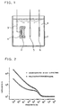
Figure 1 is a vertical cross sectional view showing in
simplified form the construction of an apparatus for evaluating
the electrochemical properties of a molded electrode in one
example of the present invention.
Figure 2 is a diagram showing AC impedance spectra for
the molded electrodes of the same example and a comparative
example.
Figure 3 is a vertical cross sectional view showing in
simplified form the construction of an apparatus for evaluating
the electrochemical properties of a molded electrode in another
example of the present invention.
Figure 4 is a diagram showing AC impedance spectra for
the molded electrodes of the same example and comparative
examples.
Figure 5 is a vertical cross sectional view of a
lithium cell according to still another example of the present
invention.
Figure 6 is a diagram showing the charge/discharge
cycle characteristics of the lithium cells of the same example
and a comparative example.
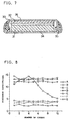
Figure 7 is a vertical cross sectional view of an all-solid
lithium cell according to yet another example of the
present invention.
Figure 8 is a diagram shoving the charge/discharge
cycle characteristics of the all-solid lithium cells of the same
example and comparative examples.
Figure 9 is a vertical cross sectional view of a
display electrode of an electroluminescent display device
according to a further example of the present invention.
Figure 10 is a vertical cross sectional view of the
display device.
BEST MODE FOR CARRYING OUT THE INVENTION
The present invention is based on the findings of the
present inventors that by using as a polymer compound a
hydrogenated block copolymer having a crystalline polyethylene-like
structural block and an olefin skeleton rubber-like block,
the ion transfer between substances constituting an
electrochemical device, for example, between inorganic solid
electrolyte particles, between electrode active material
particles, or across the interface between the electrode active
material and the electrolyte, is facilitated and high formability
and flexibility can be given to a molded solid electrolyte, a
molded electrode and the like, to improve their workability.
For example, if a polymer compound is mixed to give
flexibility to an inorganic solid electrolyte, the surfaces of
the inorganic solid electrolyte particles would be covered with
the insulating polymer compound. Asthe result, ionic conduction
between the solid electrolyte particles is interfered, and the
ionic conductivity of the resulting complex of the ion conductive
inorganic solid electrolyte and the polymer compound would
decrease. However, if the hydrogenated block copolymer having a
crystalline polyethylene-like structural block and a rubber-like
block with olefin network according to the present invention is
used as the polymer compound, the bonding between the solid
electrolyte particles can be increased without appreciably
impairing the high ionic conductivity and flexibility and the
like are given to the molded solid electrolyte.
The hydrogenated block copolymer according to the
present invention, bu introducing the crystalline polyethylene-like
structural block thereinto, can give flexibility even in a
small amount and a lithium ion conductive molded article having
high conductivity can be obtained.
The present invention will be described in detail
below.
The 1,2-vinyl bond content in block A before
hydrogenation is an important factor that determines the melting
point attributed to the block A and the cohesive force between
the polyethylene-like structural blocks after hydrogenation. In
particular, if the cohesive force drops, it becomes impossible to
reduce the amount to be added, and a lithium ion conductive
complex having high conductivity cannot be obtained.
The 1,2-vinyl bond content in the block A must be 15%
or less. If the 1,2-vinyl bond content in the block A exceeds
15%, the cohesive force of the block A after hydrogenation
decreases, which is undesirable, and the melting point also
drops, which is also undesirable.
Block B before hydrogenation is a block segment
comprising a butadiene (co)polymer which consists of 50 to 100 %
by weight of butadiene and 0 to 50 % by weight of other monomers,
with the 1,2-vinyl bond content of the butadiene being 20 to 90%,
and becomes a rubber-like block by hydrogenation.
In the block B, since the 1,2-vinyl bond of the
butadiene becomes a butene structure by hydrogenation, the
content directly influences the glass transition temperature
attributed to the block B after hydrogenation and, in the complex
with the lithium ion conductive solid electrolyte, becomes a
factor that influences flexibility.
In the present invention, the 1,2-vinyl bond content
in the block B must be 20% or higher but not exceed 90%. If the
1,2-vinyl bond content in the block B is less than 20%,
crystalline parts occur after hydrogenation and flexibility
decreases, which is not desirable. On the other hand, if it
exceeds 90%, the butene content increases excessively to raise
the glass transition temperature; this decreases the flexibility
and is not desirable.
As other monomers copolymerizable with the butadiene
in the block B, there are aromatic vinyl compounds such as
styrene, α-methyl styrene and para-methyl styrene, (meth)acrylate
esters such as methyl methacrylate and methyl acrylate, and
isoprene and the like; of these, styrene and isoprene are
particularly preferable.
The amount of these monomers used is 0 to 50% of all
the monomers constituting the block B. When these monomers are
used, if the amount of other monomers used exceeds 50%,
flexibility after hydrogenation drops, which is not desirable.
Further, the block copolymer before hydrogenation may include a
polymer block (hereinafter referred to as the block X) composed
primarily of an aromatic vinyl compound.
The hydrogenated block copolymer of the present
invention is a hydrogenated block copolymer obtained by
hydrogenating a straight chain or branched block copolymer
containing at least one block A, at least one block B, and, if
necessary, block X.
The unhydrogenated block copolymer is, to be specific,
a copolymer expressed by the structural formula A-(B-A)l, (A-B)m
wherein l and m are 1 or larger or (A-B-X)n wherein n is 1 or
larger.
Among block copolymers having such a structure, a tri-block
copolymer of A-B-A or a tri-block copolymer of A-B-X
wherein X is a polystyrene block is preferable.
The ratio of the block A to the block B in the
unhydrogenated block copolymer is block A / Block B = 5 to 70 /
95 to 30 % by weight.
If the block A in the unhydrogenated block copolymer
is less than 5 % by weight with the block B exceeding 95 % by
weight, the crystalline block segment is not sufficient and the
cohesive force decreases; as the result, high formability cannot
be obtained in a range where the adding amount is small. If the
block A exceeds 70 % by weight with the block B less than 30 % by
weight, the hardness of the hydrogenated block copolymer
increases and flexibility is lost.
In the case of the unhydrogenated block copolymer of
(A-B-X)n, the ratio of the block X in the unhydrogenated block
copolymer is usually 50 % by weight or less, preferably 40 % by
weight or less, and more preferably 30 % by weight or less.
If the block X exceeds 50 % by weight, the flexibility
of the hydrogenated block copolymer decreases and hence, the
flexibility of the molded solid electrolyte decreases. Here
also, it is desirable that the ratio of the block A to the block
B be held within the earlier noted range, in the portion
excluding the block X.
The percentage of the hydrogen added to the block
copolymer, after hydrogenation, must be 90% or higher. If the
percentage of the hydrogenation is less than 90%, the melting
point drops and the heat resistance decreases.
The hydrogenated block copolymer has the
characteristic of exhibiting the melting point attributed to the
block A after hydrogenation at a higher temperature side and the
glass transition point attributed to the block B after
hydrogenation at a lower temperature side.
The melting point of the hydrogenated block copolymer
is a factor that directly affects the heat resistance of the
composition of the present invention, and is usually 80°C or
higher, preferably 85°C or higher, and particularly preferably
95°C or higher. If the melting point is lower than 80°C, the heat
resistance of the composition is not enough and poses a problem
in practical use. In conventional electrochemical devices, an
upper limit to the operating temperature range of the device is
imposed by the boiling point of the electrolyte used; in the case
of an electrochemical device using a solid electrolyte as the
electrolyte, the upper limit of the operating temperature range
becomes higher. Further, since an activation energy of the
conduction of a solid electrolyte is generally higher than that
of a liquid electrolyte, ion transfer at higher speed at a higher
temperature in the electrolyte and, therefore, electrochemical
devices using solid electrolytes exhibit superior properties at
high temperature to those of devices using liquid electrolytes.
Accordingly, it is required that the polymer compound used have
high heat resistance. Further, in the case of a fuel cell or the
like using a proton conducting solid electrolyte, the temperature
of the device can rise close to 100°C because of the heat
generated during device operation. It is, therefore, more
preferable that the melting point of the hydrogenated block
copolymer is 95°C or higher.
The glass transition temperature at a lower
temperature side of the hydrogenated block copolymer, on the
other hand, is a factor that affects the low temperature
characteristics of the composition, and is usually -25°C or
lower, preferably -30°C or lower, and particularly preferably -
35°C or lower. If the glass transition temperature at a lower
temperature side is higher than -25°C, dynamic properties at low
temperatures degrade, and also the ionic conductivity at a lower
temperature side of the composition decreases significantly.
The hydrogenated block copolymer can be produced by
using known techniques. For example, the method disclosed in
Japanese Patent Unexamined Publication No. 4-342752 can be used.
As solid electrolytes so far found to exhibit ionic
conductivity of 10-4 S/cm or higher at room temperature, there
have been found solid electrolytes of copper ion conductive,
silver ion conductive, proton conducting, and fluoride ion
conductive and the like. Among others, the lithium ion
conductive solid electrolyte has been attracting attention as an
electrolyte for all-solid lithium cells. However, lithium cells
which generate high voltage comprise a cathode that exhibits a
strong oxidizing power and an anode that exhibits a strong
reducing power. Therefore, even if the polymer compound added to
the electrolyte layer exhibits the characteristic that does not
interfere with ion transfer and that provides a high binding
property, deterioration may occur through contact with the
cathode or anode. However, the hydrogenated block copolymer of
the present invention is stable to such oxidation reduction
reactions and, thus, offers the greatest effect when used with a
lithium ion conductive solid electrolyte for the construction of
a molded solid electrolyte.
The kinds of the solid electrolyte, for example in the
case of lithium ion conductive electrolytes, may be divuded into
the crystalline type such as Li1.3Sc0.3Ti1.7(PO4)3 and
Li0.2La0.6TiO3, and the amorphous type such as Li2S-SiS2. Many
crystalline solid electrolytes show anisotropy to ionic
conductivity, and in order to realize a high ionic conductivity,
it often becomes necessary to sinter the molded article and
connect ion conductive paths between solid electrolyte particles.
On the other hand, amorphous solid electrolytes show isotropy to
ionic conductivity, and ion conductive paths between particles
can be easily connected by a pressure molding process. It is
therefore preferable to use an amorphous solid electrolyte for a
molded solid electrolyte if it is intended to simplify the
process of electrochemical device fabrication.
Lithium ion conductive amorphous solid electrolytes
include those consisting essentially sulfides such as Li2S-SiS2,
and those consisting essentially oxides such as Li2S-SiO2.
Electrolytes consisting primarily of sulfides have high
reactivity with moisture and the like, and there is a need to use
a nonpolar solvent when mixing with a polymer compound. The
hydrogenated block copolymer of the present invention is soluble
in a nonpolar solvent, and can form a complex without impairing
the properties of lithium ion conductive amorphous solid
electrolytes consisting essentially sulfides.
For lithium ion conductive inorganic solid
electrolytes, those having a high ionic conductivity and wide
potential window are preferable, and amorphous electrolytes
consisting primarily of sulfides, which possess both of these
characteristics, are particularly preferable.
For lithium ion conductive amorphous inorganic solid
electrolytes, if a lithium sulfide and a silicon sulfide are used
as starting materials, evaporation of the starting materials can
be suppressed when synthesizing the solid electrolyte, since the
vapor pressure of the starting materials is low. This serves to
simplify the process of solid electrolyte synthesis: therefore,
for lithium ion conductive amorphous inorganic compounds, those
containing silicon are particularly preferable for use.
Further, by adding an electronically insulating
structural member, the mechanical strength of the lithium ion
conductive molded solid electrolyte can be further increased.
For specific examples of the electronically insulating
structural member, there are a woven fabric, non-woven fabric,
porous film, and the like.
In a method of producing the molded solid electrolyte
of the present invention, a hydrogenated block copolymer solution
is added to solid electrolyte powder and, then, mixed and
dispersed using a paint conditioner or the like to obtain a
slurry with the solid electrolyte powder dispersed through the
hydrogenated block copolymer solution. Next, the slurry is
applied onto a substrate having releasing property to obtain a
film-like molded solid electrolyte; alternatively, the slurry is
applied to or impregnated into an electronically insulating
structural member such as a woven fabric to obtain a sheet-like
molded solid electrolyte.
The hydrogenated block copolymer of the present
invention, when complexed with other particles, does not
interfere with ion transfer, provides good inter-particle
bonding, and permits the production of a molded article having
high workability. Further, in the electrodes used in an
electrochemical device, ions are transferred between the
electrode active material and the electrolyte. As previously
noted, high formability must be given to the electrodes without
interfering with the ion transfer; therefore, by using the
hydrogenated block copolymer of the present invention, a molded
electrode that can satisfy these requirements can be produced.
Furthermore, when a solid electrolyte is used as the
electrolyte, if a binder is added to improve the formability, the
electrode reaction speed tends to drop, which is a problem as
previously noted; therefore, using the hydrogenated block
copolymer as the binder is particularly effective.
Moreover, for the active material used as the
electrode active material in lithium cells, the oxidation
reduction resistance of the binder is important, as previously
stated: for this reason also, using the hydrogenated block
copolymer is particularly effective. In that case, the molded
electrode contains the electrode active material or the electrode
active material and solid electrolyte, and the solid electrolyte
used is of the lithium ion conductive type.
For the lithium ion conductive solid electrolyte, the
amorphous type is preferable, since it does not have anisotropy
with respect to ion conductive paths and thus makes it easy to
connect ion conductive paths between the electrode active
material and the electrolyte. For the amorphous lithium ion
conductive solid electrolyte, an electrolyte consisting
essentially of a sulfide is particularly preferable for use,
since such an electrolyte exhibits a high ionic conductivity and
wide potential window.
Further, by adding a structural member to the molded
electrode, the mechanical strength of the molded electrode can be
further increased. A structural member formed from an electron
conductive material is particularly preferable for use, since
such a structure serves to increase the electron conductivity
within the electrode. Examples of the electron conductive
structural member that can be used here are a metallic mesh and
the like formed from stainless steel, titanium, copper, and the
like.
The hydrogenated block copolymer used in the present
invention contains a rubber-like block with olefin skeleton as
well as a crystalline polyethylene-like structural block. The
rubber-like block with olefin skeleton has a large free volume,
and can therefore absorb the volumetric change of the electrode
active material occurring during the operation of the
electrochemical device. Further, since the crystalline
polyethylene-like structural block provides strong bonding and
flexibility between the constituent particles of the
electrochemical device, problems associated with the decreased
inter-particle bonding due to the volumetric change of the active
material can be resolved, and an electrochemical device that is
stable in operation can thus be achieved.
The present invention will be described in detail
below by way of example.
The synthesis of lithium ion conductive inorganic
solid electrolytes and the measurement of their ion conductivity
hereinafter described were all conducted in a dry argon
atmosphere.
First, synthesizing examples of hydrogenated block
copolymers will be described. In Table 1, the structures and
properties of the hydrogenated block copolymers are shown. In
the table, A, B, and X in the component structural formula
represents the block A, block B, and polystyrene block,
respectively.
Methods of their production are shown below.
1) Production of the hydrogenated block copolymer (H-1)
3.2 kg of cyclohexane and 1.2 kg of butadiene are
introduced into an autoclave with a net capacity of 20 liters,
and 33 ml of a 14 % by weight tetrahydrofuran solution of n-butyl
lithium is added. The mixture is heated to about 70°C, and when
the percentage of addition reaches 100%, 2.8 kg of butadiene and
108 ml of tetrahydrofuran are further added, and the
polymerization is continued at about 70°C. When the percentage
of addition reaches 100%, 26 ml of a 20 % by weight
tetrahydrofuran solution of dicyclosilane is added, and is
allowed to react for about 20 minutes, thereby coupling diblock
polymers to obtain a triblock copolymer. After the completion of
the polymerization, the reaction solution is maintained at about
70°C, and 3 g of n-butyl lithium, 3 g of 2,6-di-t-butyl-p-cresol,
1 g of bis(cyclopentadienyl)titanium dichloride, and 2 g of
diethylaluminum chloride are added, and are allowed to react for
one hour under a hydrogen pressure of 10 kg/cm2. After stream
stripping, the reaction liquid is dried on rolls, to obtain the
hydrogenated block copolymer (H-1).
2) Production of the hydrogenated block copolymers (H-2) to (H-4)
Similarly to the production of the hydrogenated block
copolymer (H-1), the hydrogenated block copolymers (H-2) to (H-4)
are obtained by varying the monomer combination, monomer amounts,
catalyst amounts, polymerization temperature, polymerization time
and the like to give the hydrogenated block copolymer produced as
shown in Table 1.
| Sample number | H-1 | H-2 | H-3 | H-4 |
| Component structural formula | A-B-A | A-B-A | A-B-A | A-B-X | |
| 1,2-vinyl bond content (%) in block A | 12 | 13 | 12 | 13 |
| Amount of block A (% by weight) | 30 (15x2) | 20 (10x2) | 40 (20x2) | 15 |
| 1,2-vinyl bond content (%) in block B | 42 | 41 | 65 | 42 |
| Amount of block B (% by weight) | 70 | 80 | 60 | 70 |
| Amount of block X (% by weight) | | | | 15 |
| Properties |
| Percentage of hydrogenation (%) | 98 | 97 | 98.5 | 97.5 |
| Melting point (at higher temperature side) | 92 | 89 | 90 | 92 |
| Glass transition temperature (at lower temperature side) | -52 | -54 | -55 | -51 |
| MFR (230°C x 2.16kg) | 10 | 5 | 8 | 0.5 |
| Molecular weight (× 104) | 15 | 20 | 15 | 15 |
A lithium ion conductive molded solid electrolyte was
obtained by using a lithium ion conductive glass sulfide
represented by 0.6Li2S-0.4SiS2 as the solid electrolyte and (H-1)
as the hydrogenated block copolymer. The details are shown
below.
First, as the solid electrolyte, the lithium ion
conductive amorphous solid electrolyte represented by 0.6Li2S-0.4SiS2
was synthesized in the following manner.
Lithium sulfide (Li2S) and silicon sulfide (SiS2) were
mixed at a ratio of 0.6:0.4 by mole, and the mixture was
introduced into a glass-like carbon crucible. The crucible was
then placed in a vertical furnace and heated up to 950°C in an
argon stream to melt the mixture. After heating for two hours,
the crucible was dropped into liquid nitrogen for rapid cooling,
to obtain the lithium ion conductive amorphous solid electrolyte
represented by 0.6Li2S-0.4SiS2.
Using the thus obtained lithium ion conductive
amorphous solid electrolyte and the hydrogenated block copolymer
(H-1), the lithium ion conductive molded solid electrolyte was
produced in the following manner.
First, the solid electrolyte obtained in the above
process was pulverized to 350 mesh or finer powder. To the solid
electrolyte powder, a toluene solution of (H-1) was then added,
and thoroughly kneaded to obtain a slurry. The mixing ratio,
when kneading, was chosen such that the solid content of the
hydrogenated block copolymer to the solid electrolyte powder was
2:98 by weight. The thus obtained slurry was applied onto a
fluorocarbon resin plate by a doctor blade method, and was dried
by allowing the toluene to evaporate under a reduced pressure at
100°C. After drying for three hours, by separating from the
fluorocarbon resin plate, the lithium ion conductive molded solid
electrolyte was obtained.
The ionic conductivity of the lithium ion conductive
molded solid electrolyte was measured by the AC impedance method
described below.
First, the lithium ion conductive molded solid
electrolyte sheet obtained in the above process was cut out into
the shape of a disk with a diameter of 10 mm. Then, a 10-mm
diameter platinum plate as impedance measuring electrode was
adhered by pressure onto each side of the disk to form an ionic
conductivity measuring cell.
The AC impedance was measured by applying an AC
voltage of 10 mV using a vector impedance analyzer. As the
result, the ionic conductivity of the lithium ion conductive
molded solid electrolyte thus measured was 2.45 × 10⁻⁴ S/cm.
As a comparative example, the solid electrolyte powder
was pressure molded without adding the hydrogenated block
copolymer, and when the ionic conductivity was measured in the
same manner, the result showed 4.5 × 10⁻⁴ S/cm.
Next, to examine the flexibility of the lithium ion
conductive molded solid electrolyte for the evaluation of
workability, a bending test was conducted. The bending test was
carried out by winding the lithium ion conductive molded solid
electrolyte around a 50-mm diameter stainless steel rod and
visually inspecting the condition of the molded article. The
result showed that no externally discernible faults were observed
on the lithium ion conductive molded solid electrolyte of this
example, thus demonstrating that the molded article had high
flexibility evev in the bending test.
As described above, it has been found that, according
to the present invention, a lithium ion conductive molded solid
electrolyte having a high lithium ion conductivity and excellent
workability can be obtained.
EXAMPLE 2
Except that (H-1) used as the hydrogenated block
copolymer in EXAMPLE 1 was replaced by (H-2), a lithium ion
conductive molded solid electrolyte was obtained in the same
manner as in EXAMPLE 1.
When the ionic conductivity of the lithium ion
conductive molded solid electrolyte was measured in the same
manner as in EXAMPLE 1, the result showed 2.8 × 10⁻⁴ S/cm.
Further, in the bending test conducted in the same
manner as in EXAMPLE 1, no externally discernible faults were
observed, thus demonstrating that the electrolyte had high
flexibility.
EXAMPLE 3
Except that (H-1) used as the hydrogenated block
copolymer in EXAMPLE 1 was replaced by (H-3), a lithium ion
conductive molded solid electrolyte was obtained in the same
manner as in EXAMPLE 1.
When the ionic conductivity of the lithium ion
conductive molded solid electrolyte was measured in the same
manner as in EXAMPLE 1, the result showed 3.4 × 10⁻⁴ S/cm.
Further, in the bending test conducted in the same
manner as in EXAMPLE 1, no externally discernible faults were
observed, thus demonstrating that the electrolyte had high
flexibility.
EXAMPLE 4
Except that (H-1) used as the hydrogenated block
copolymer in EXAMPLE 1 was replaced by (H-4), a lithium ion
conductive molded solid electrolyte was obtained in the same
manner as in EXAMPLE 1.
When the ionic conductivity of the lithium ion
conductive molded solid electrolyte was measured in the same
manner as in EXAMPLE 1, the result showed 2.5 × 10⁻⁴ S/cm.
Further, in the bending test conducted in the same
manner as in EXAMPLE 1, no externally discernible faults were
observed, thus demonstrating that the electrolyte had high
flexibility.
EXAMPLE 5
A lithium ion conductive molded solid electrolyte was
produced by using a lithium ion conductive amorphous solid
electrolyte represented by 0.01Li3PO4-0.63Li2S-0.36SiS2 as the
lithium ion conductive inorganic solid electrolyte and, as in
EXAMPLE 3, (H-3) as the hydrogenated block copolymer. The
details are shown below.
First, as the lithium ion conductive inorganic solid
electrolyte, the lithium ion conductive amorphous solid
electrolyte represented by 0.01Li3PO4-0.63Li2S-0.36SiS2 was
synthesized in the following manner.
First, a glass matrix for synthesizing the amorphous
solid electrolyte was synthesized. Lithium sulfide (Li2S) and
silicon sulfide (SiS2) were mixed at a ratio of 0.64:0.36 by
mole, and the mixture was introduced into a glass-like carbon
crucible and melted at 950°C in a horizontal furnace. After
that, the molten liquid was rapidly cooled on a twin roller, to
obtain an amorphous solid electrolyte represented by 0.64Li2S-0.36SiS2.
This amorphous solid electrolyte as the glass matrix
was pulverized, and lithium phosphate was mixed into the powder
so as to provide the composition 0.01Li3PO4-0.63Li2S-0.36SiS2.
This mixture was heated and then rapidly cooled in the same
manner as above, to obtain the lithium ion conductive amorphous
solid electrolyte represented by 0.01Li3PO4-0.63Li2S-0.36SiS2.
Except that the solid electrolyte obtained in the
above process was used in place of the solid electrolyte
represented by 0.6Li2S-0.4SiS2 and that (H-3) used in EXAMPLE 3
was used as the hydrogenated block copolymer, the lithium ion
conductive molded solid electrolyte was then obtained in the same
manner as in EXAMPLE 1.
When the ionic conductivity of the lithium ion
conductive molded solid electrolyte was measured in the same
manner as in EXAMPLE 1, the result showed 5.3 × 10⁻⁴ S/cm. As a
comparative example, when the ionic conductivity of the solid
electrolyte powder itself was measured in the same manner as in
EXAMPLE 1, the result showed 7.8 × 10⁻⁴ S/cm.
Further, in the bending test conducted in the same
manner as in EXAMPLE 1, no externally discernible faults were
observed, thus demonstrating that the electrolyte had high
flexibility.
EXAMPLE 6
By using a lithium ion conductive amorphous solid
electrolyte represented by 0.05Li2O-0.60Li2S-0.35SiS2 as the
lithium ion conductive inorganic solid electrolyte and, as in
EXAMPLE 3, (H-3) as the hydrogenated block copolymer, a lithium
ion conductive molded solid electrolyte was produced. The
details are shown below.
The lithium ion conductive amorphous solid electrolyte
represented by 0.05Li2O-0.60Li2S-0.35SiS2 was synthesized in the
same manner as in EXAMPLE 5, except that lithium oxide was used
in place of lithium phosphate.
Except that the lithium ion conductive solid
electrolyte obtained in the above process was used, and that (H-3)
used in EXAMPLE 3 was used as the hydrogenated block
copolymer, the lithium ion conductive molded solid electrolyte
was obtained in the same manner as in EXAMPLE 1.
When the ionic conductivity of the lithium ion
conductive molded solid electrolyte was measured in the same
manner as in EXAMPLE 1, the result showed 4.3 × 10⁻⁴ S/cm. As a
comparative example, when the ionic conductivity of the solid
electrolyte powder itself was measured in the same manner as in
EXAMPLE 1, the result showed 6.6 × 10⁻⁴ S/cm.
Further, in the bending test conducted in the same
manner as in EXAMPLE 1, no externally discernible faults were
observed, thus demonstrating that the electrolyte had high
flexibility.
EXAMPLE 7
A lithium ion conductive molded solid electrolyte was
produced by using a lithium ion conductive amorphous solid
electrolyte represented by 0.30LiI-0.35Li2S-0.35SiS2 as the
lithium ion conductive inorganic solid electrolyte and, as in
EXAMPLE 1, (H-1) as the hydrogenated block copolymer. The
details are shown below.
To begin with, as the lithium ion conductive inorganic
solid electrolyte, the lithium ion conductive amorphous solid
electrolyte represented by 0.30LiI-0.35Li2S-0.35SiS2 was
synthesized in the following manner.
First, except that the mixing ratio of the starting
materials was varied, an amorphous solid electrolyte represented
by 0.5Li2S-0.5SiS2 was obtained in the same manner as in EXAMPLE
1. This amorphous solid electrolyte as a glass matrix was
pulverized, and lithium iodide was mixed into the powder so as to
provide the composition 0.30LiI-0.35Li2S-0.35SiS2. This mixture
was again heated and rapidly cooled in like manner, to obtain the
lithium ion conductive amorphous solid electrolyte represented by
0.30LiI-0.35Li2S-0.35SiS2.
Except that the solid electrolyte obtained in the
above process was used in place of the solid electrolyte
represented by 0.6Li2S-0.4SiS2, the lithium ion conductive molded
solid electrolyte was then obtained in the same manner as in
EXAMPLE 1.
When the ionic conductivity of the lithium ion
conductive molded solid electrolyte was measured in the same
manner as in EXAMPLE 1, the result showed 3.5 × 10⁻⁴ S/cm. As a
comparative example, when the ionic conductivity of the solid
electrolyte powder itself was measured in the same manner as in
EXAMPLE 1, the result showed 7.2 × 10⁻⁴ S/cm.
Further, in the bending test conducted in the same
manner as in EXAMPLE 1, no externally discernible faults were
observed, thus demonstrating that the electrolyte had high
flexibility.
EXAMPLE 8
A lithium ion conductive molded solid electrolyte was
produced by using a lithium ion conductive amorphous solid
electrolyte represented by 0.5Li2S-0.5P2S5 as the lithium ion
conductive inorganic solid electrolyte and, as in EXAMPLE 1, (H-1)
as the hydrogenated block copolymer. The details are shown
below.
First, as raw materials for the solid electrolyte,
lithium sulfide (Li2S) and phosphorus sulfide (P2S5) were mixed at
a ratio of 0.5:0.5 by mole. The mixture was then sealed within a
silica tube and melted at 900°C, after which the silica tube was
immersed into water for rapid cooling, to obtain the amorphous
solid electrolyte represented by 0.5Li2S-0.5P2S5.
Except that the solid electrolyte obtained in the
above process was used in place of the solid electrolyte
represented by 0.6Li2S-0.4SiS2, the lithium ion conductive molded
solid electrolyte was then obtained in the same manner as in
EXAMPLE 1.
When the ionic conductivity of the lithium ion
conductive molded solid electrolyte and that of the solid
electrolyte powder as a comparative example were measured in the
same manner as in EXAMPLE 1, the results showed that the ionic
conductivity of the molded solid electrolyte with the
hydrogenated block copolymer added thereto was 1.0 × 10⁻⁴ S/cm, as
compared with 1.6 × 10⁻⁴ S/cm for the solid electrolyte itself,
the rate of decrease thus being held within one half.
Further, in the bending test conducted in the same
manner as in EXAMPLE 1, no externally discernible faults were
observed, thus demonstrating that the electrolyte had high
flexibility.
EXAMPLE 9
A lithium ion conductive molded solid electrolyte was
produced by using a lithium ion conductive amorphous solid
electrolyte represented by 0.6Li2S-0.4B2S3 as the lithium ion
conductive inorganic solid electrolyte and, as in EXAMPLE 1, (H-1)
as the hydrogenated block copolymer. The details are shown
below.
First, except that lithium sulfide (Li2S) and boron
sulfide (B2S3) mixed at a ratio of 0.6:0.4 by mole were used as
the raw materials for the solid electrolyte, the amorphous solid
electrolyte represented by 0.6Li2S-0.4B2S3 was obtained in the
same manner as in EXAMPLE 8.
Except that the solid electrolyte obtained in the
above process was used in place of the solid electrolyte
represented by 0.6Li2S-0.4SiSB2, the lithium ion conductive molded
solid electrolyte was then obtained in the same manner as in
EXAMPLE 1.
When the ionic conductivity of the lithium ion
conductive molded solid electrolyte and that of the solid
electrolyte powder as a comparative example were measured in the
same manner as in EXAMPLE 1, the results showed that the ionic
conductivity of the molded solid electrolyte with the
hydrogenated block copolymer added thereto was 1.2 × 10⁻⁴ S/cm, as
compared with 1.9 × 10⁻⁴ S/cm for the solid electrolyte itself,
the rate of decrease thus being held within one half.
Further, in the bending test conducted in the same
manner as in EXAMPLE 1, no externally discernible faults were
observed, thus demonstrating that the electrolyte had high
flexibility.
EXAMPLE 10
Using an amorphous solid electrolyte represented by
0.6Li2S-0.4SiS2 as the lithium ion inorganic solid electrolyte, as
in EXAMPLE 1, and using (H-3) as the hydrogenated block
copolymer, various lithium ion conductive molded solid
electrolytes were obtained by varying the composition ratio
between the lithium ion conductive inorganic solid electrolyte
and the hydrogenated block copolymer. The details are shown
below.
Using the lithium ion conductive inorganic solid
electrolyte obtained in EXAMPLE 1 and (H-3), lithium ion
conductive molded solid electrolytes with varying composition
ratios were obtained by the same method as used in EXAMPLE 1.
Table 2 shows the composition ratio versus ionic
conductivity relationships of the various lithium ion conductive
molded solid electrolytes. Table 2 also shows the results of the
bending test.
| Ratio of copolymer (% by weight) | 0.4 | 1.0 | 2.0 | 3.5 | 5.0 |
| Ratio of solid electrolyte (% by weight) | 99.6 | 99.0 | 98.0 | 96.5 | 95.0 |
| Ionic conductivity (x10-4S/cm) | 4.1 | 3.8 | 3.4 | 2.8 | 2.0 |
| Bendding test | Good | Good | Good | Good | Good |
| Remarks | | | Example 3 |
From the above results, it can be seen that by using
the hydrogenated block copolymer in only small amounts, a lithium
ion conductive molded solid electrolyte can be obtained that has
excellent flexibility as well as a very high ionic conductivity.
The hydrogenated block copolymer has the characteristic that even
if it is added in relatively large amounts, the decrease in the
ionic conductivity is small.
EXAMPLE 11
A lithium ion conductive molded solid electrolyte was
obtained by using the amorphous solid electrolyte represented by
0.01Li3PO4-0.63Li2S-0.36SiS2 obtained in EXAMPLE 5 as the lithium
ion conductive inorganic solid electrolyte, and (H-3) as the
hydrogenated block copolymer, and also using a polyethylene mesh
as the electronically insulating structural member. The details
are shown below.
The slurry containing the solid electrolyte and
designated polymers was obtained in the same manner as in EXAMPLE
1. Next, using a doctor blade method, the slurry was charged
into the openings in a polyethylene mesh having a porosity of
70%. After that, by drying the mesh by evaporating the toluene
under a reduced pressure at 40°C, thus obtaining the lithium ion
conductive molded solid electrolyte.
The ionic conductivity of the lithium ion conductive
molded solid electrolyte, when measured in the same manner as in
EXAMPLE 1, was 3.0 × 10⁻⁴ S/cm.
In the bending test conducted in the same manner as in
EXAMPLE 1, no externally discernible faults were observed, and
also, in the bending test conducted using a 5-mm diameter
stainless steel rod, no faults were observed, thus demonstrating
that the lithium ion conductor according to this example had high
flexibility.
As described above, it has been found that a lithium
ion conductive molded solid electrolyte having particularly high
workability as well as a high lithium ion conductivity can be
obtained according to the present invention using a lithium ion
conductive inorganic solid electrolyte, a hydrogenated block
copolymer, and an electronically insulating structural member.
EXAMPLE 12
Except that the 0.01Li3PO4-0.63Li2S-0.36SiS2 used as
the lithium ion conductive inorganic solid electrolyte in EXAMPLE
11 was replaced by the lithium ion conductive amorphous solid
electrolyte represented by 0.6Li2S-0.4SiS2 obtained in EXAMPLE 1,
that (H-3) used as the hydrogenated block copolymer in EXAMPLE 11
was replaced by (H-1), and that the polyethylene mesh used as the
electronically insulating structural member in EXAMPLE 11 was
replaced by a glass fiber mesh, a lithium ion conductive molded
solid electrolyte was produced in the same manner as in EXAMPLE
11.
The ionic conductivity of the resulting lithium ion
conductive molded solid electrolyte, when measured in the same
manner as in EXAMPLE 1, was 3.3 × 10⁻⁴ S/cm.
In the bending test conducted in the same manner as in
EXAMPLE 1, no externally discernible faults were observed, and
also, in the bending test conducted using a 5-mm diameter
stainless steel rod, no faults were observed, thus demonstrating
that the lithium ion conductive molded solid electrolyte
according to this example had high flexibility.
COMPARATIVE EXAMPLE 1
Using a styrene-ethylene-butylene-styrene block
copolymer (KRATON G1652 manufactured by SHELL, hereinafter
designated SEBS) having no crystalline block structures, and
using, as in EXAMPLE 1, an amorphous solid electrolyte
represented by 0.6Li2S-0.4SiS2 as the lithium ion conductive
inorganic solid electrolyte, various lithium ion conductive
molded solid electrolytes were obtained by varying the
composition ratio of the lithium ion conductive inorganic solid
electrolyte and the SEBS. The details are shown below.
Using the SEBS and the lithium ion conductive
inorganic solid electrolyte obtained in EXAMPLE 1, lithium ion
conductive molded solid electrolytes with varying composition
ratios were obtained by the same method as used in EXAMPLE 1.
Table 3 shows the composition ratio versus ionic
conductivity relationships of the various lithium ion conductive
molded solid electrolytes. Table 3 also shows the results of the
bending test.
| Ratio of copolymer (% by weight) | 0.4 | 1.0 | 2.0 | 3.5 | 5.0 |
| Ratio of solid electrolyte (% by weight) | 99.6 | 99.0 | 98.0 | 96.5 | 95.0 |
| Ionic conductivity (x10-4S/cm) | - | - | - | 0.9 | 0.5 |
| Bendding test | Unable to recover as a molded article | Unable to recover as a molded article | Unable to recover as a molded article | Cracks developed | Good |
| Remarks | Unable to recover as a molded article; hence unable to measure conductivity |
Using a copolymer (hereinafter designated H-SBR)
obtained by hydrogenating a styrene-butadiene random copolymer,
which was produced by polymerizing 5 % by weight of styrene and
95 % by weight of butadiene, with the 1,2-vinyl bond content of
the butadiene being 80%, and using, as in EXAMPLE 1, an amorphous
solid electrolyte represented by 0.6Li2S-0.4SiS2 as the lithium
ion inorganic solid electrolyte, various lithium ion conductive
molded solid electrolytes were obtained by varying the
composition ratio between the lithium ion conductive inorganic
solid electrolyte and the H-SBR. The details are shown below.
Using the H-SBR and the lithium ion conductive
inorganic solid electrolyte obtained in EXAMPLE 1, lithium ion
conductive molded solid electrolytes with varying composition
ratios were obtained by the same method as used in EXAMPLE 1.
Table 4 shows the composition ratio versus ionic
conductivity relationships of the various lithium ion conductive
molded solid electrolytes. Table 4 also shows the results of the
bending test.
| Ratio of H-SBR (% by weight) | 0.4 | 1.0 | 2.0 | 3.5 | 5.0 |
| Ratio of solid electrolyte (% by weight) | 99.6 | 99.0 | 98.0 | 96.5 | 95.0 |
| Ionic conductivity (x10-4S/cm) | - | - | - | - | 0.4 |
| Bendding test | Unable to recover as a molded article | Unable to recover as a molded article | Unable to recover as a molded article | Unable to recover as a molded article | Good |
| Remarks | Unable to recover as a molded article; hence unable to measure conductivity |
From the comparison between the EXAMPLES and the
COMPARATIVE EXAMPLES, it can be seen that the hydrogenated block
copolymer of the present invention having a crystalline block
provides good workability and excellent flexibility and is a
suitable material for obtaining a lithium ion conductive molded
solid electrolyte having a high ionic conductivity.
EXAMPLE 13
In this example, a proton conducting molded solid
electrolyte was produced by using silica gel doped with
phosphoric acid as the proton conducting solid electrolyte and
(H-1) as the hydrogenated block copolymer.
First, silica gel doped with phosphoric acid was
synthesized in the following manner.
Tetraethoxysilane (hereinafter designated TEOS) was
used as the starting material for synthesizing the silica gel,
and was diluted with ethanol. Here, the mixing ratio of the TEOS
to the ethanol was chosen to be 1:4 by mole. To this solution
were added eight parts of pure water and 0.01 parts of
tetraethylammonium tetrafluoroborate, the parts being by mole
with respect to the TEOS, and was further added an aqueous
solution of 3.6 % by weight hydrochloric acid, with HCl being
0.01 parts by mole with respect to the TEOS, and the resulting
mixture was stirred for five minutes. After that, an aqueous
solution of 85 % by weight phosphoric acid was added with the
ratio TEOS:H3PO4 = 1:0.5, and the mixture was stirred in a
hermetic container for three hours. The mixture was then left on
stand for five hours for gelation, and heated for two hours at
150°C. to obtain the phosphoric acid doped silica gel.
The phosphoric acid doped silica gel obtained in the
above process was pulverized and was stirred in a toluene
solution of (H-1). Here, the ratio of the proton conducting
solid electrolyte to the solid content of the (H-1) copolymer was
chosen to be 19:1 by weight. The slurry thus obtained was
applied onto a fluorocarbon resin plate by a doctor blade method,
and was dried by allowing the toluene to evaporate under a
reduced pressure at 100°C. After drying for three hours, the
resulting sheet was separated from the fluoroplastic plate, to
obtain the proton conducting molded solid electrolyte.
The ionic conductivity of the proton conducting molded
solid electrolyte, when measured by the same AC impedance method
as used in EXAMPLE 1, was 3.2 × 10⁻³ S/cm.
In the bending test conducted in the same manner as in
EXAMPLE 1, no externally discernible faults were observed, thus
demonstrating that the proton conducting molded solid electrolyte
according to this example had higher flexibility.
In this way, it has been found that a proton
conducting molded solid electrolyte having high workability and
high proton conductivity can be obtained according to the present
invention using a proton conducting inorganic solid electrolyte
and a hydrogenated block copolymer.
EXAMPLE 14
In this example, a silver ion conductive molded solid
electrolyte was produced by using a solid electrolyte represented
by Ag6I4WO4 as the silver ion conductive solid electrolyte and (H-1)
as the hydrogenated block copolymer.
First, Ag6I4WO4 was synthesized in the following
manner.
Silver iodide (AgI). silver oxide (Ag2O), and tungsten
oxide (WO3) were used as starting materials. These starting
materials were mixed together, and the mixture was heated and
melted at 400°C in a quartz crucible. Thereafter, the mixture
was allowed to cool in the furnace, to obtain the silver ion
conductive solid electrolyte represented by Ag6I4WO4.
The silver ion conductive solid electrolyte obtained
in the above process was pulverized and stirred in a toluene
solution of (H-1). Here, the ratio of the silver ion conductive
solid electrolyte to the solid content of the (H-1) copolymer was
chosen to be 97:3 by weight. The slurry thus obtained was
applied onto a fluorocarbon resin plate by a doctor blade method,
and was dried by allowing the toluene to evaporate under a
reduced pressure at 100°C. After drying for three hours, the
resulting sheet was separated from the fluorocarbon resin plate,
to obtain the silver ion conductive molded solid electrolyte.
The ionic conductivity of the silver ion conductive
molded solid electrolyte and, for comparison purposes, the ionic
conductivity of the silver ion conductive solid electrolyte
before adding the hydrogenated block copolymer, were measured by
the same AC impedance method as used in EXAMPLE 1. The result
showed that the ionic conductivity of the silver ion conductive
solid electrolyte itself was 4.0 × 10⁻² S/cm. On the other hand,
after addition of the hydrogenated block copolymer, the ionic
conductivity was 2.3 × 10⁻² S/cm, the rate of decrease relative to
the former being held within one half.
In the bending test conducted in the same manner as in
EXAMPLE 1, no externally discernible faults were observed, thus
demonstrating that the silver ion conductive molded solid
electrolyte according to this example had higher flexibility.
EXAMPLE 15
A molded electrode was obtained by using a lithiated
cobalt oxide represented by LiCoO2, which is an electron-lithium
ion mixed conductor, as the material that exhibits an
electrochemical oxidation reduction reaction in an electrolyte,
and (H-1) as the hydrogenated block copolymer. The details are
shown below.
First, LiCoO2 was synthesized by measuring and mixing
cobalt oxide (Co3O4) and lithium carbonate (Li2CO3) at a ratio of
Co/Li = 1, and by baking the mixture at 900°C in the atmosphere.
Using the thus obtained LiCoO2 and (H-1), a molded
electrode was obtained in the following manner.
First, the LiCoO2 obtained in the above process was
pulverized to 350 mesh or finer powder. A toluene solution of
(H-1) was then added to the powder of LiCoO2, and thoroughly
kneaded to obtain a slurry. The mixing ratio of the solid
content of the hydrogenated block copolymer to the LiCoO2 powder,
when kneading, was chosen to be 5:95 by weight. The slurry thus
obtained was applied onto a fluorocarbon resin plate by a doctor
blade method, and was dried by allowing the toluene to evaporate
under a reduced pressure at 100°C. After drying for three hours,
by separating from the fluorocarbon resin plate and cutting out,
a molded electrode with a diameter of 10mm and a thickness of
0.2 mm was obtained.
For comparison purposes, using a water dispersion of
polytetrafluoroethylene (hereinafter designated PTFE) in place of
the hydrogenated block copolymer used in this example, a molded
electrode was produced in like manner.
Further, for comparison purposes, a molded electrode
was produced by pressure molding LiCoO2 into the shape of a disk
10 mm in diameter and 0.2 mm in thickness, without adding a
binder such as a hydrogenated block copolymer.
The electrochemical properties of the thus obtained
molded electrodes were evaluated using the AC impedance method
described below.
Figure 1 shows in simplified form the construction of
a measuring apparatus. In the figure, numeral 1 indicates a
sample holder. The molded electrode 2 was set into the holder by
pressing and adhering against a lead terminal 3, thus forming a
test electrode. This test electrode was immersed into an
electrolyte solution 4 in a container 7. The electrolyte
solution was prepared by dissolving lithium phosphorus
hexafluoride (LiPF6) in the solvent mixture, which was obtained by
mixing propylene carbonate and dimethoxy ethane in the ratio of
1:1 by volume, so as to provide a concentration of 1.0 M. A
reference electrode 5 and a counter electrode 6 were each from a
metallic lithium foil, and were immersed in the electrolyte
solution. The measuring cell was thus formed. By applying an AC
voltage of 10 mV to the measuring cell using an impedance
analyzer, the AC impedance was measured over the frequency range
of 100 kH to 1 mHz.
The results showed that in the case of the molded
electrode produced without adding a binder, the formability of
the electrode was inferior and, during the measurement, the
electrode active material LiCoO2 was dropped off into the
electrolyte solution, making it impossible to measure the
impedance. Impedance spectra for the electrode produced using
the hydrogenated block copolymer of the present invention as the
binder and the electrode produced using the PTFE in the
comparative example were shown in Figure 2. As can be seen from
the figure, it was found that the molded electrode obtained by
using the designated polymers of the present invention as the
binder exhibited a low impedance value and achieved a high
electrode reactivity.
As described above, it has been found that a molded
electrode having a high electrode reactivity and excellent
formability can be obtained according to the present invention.
EXAMPLE 16
Except that (H-1) used as the hydrogenated block
copolymer in EXAMPLE 15 was replaced by (H-2), a molded electrode
was obtained in the same manner as in EXAMPLE 15.
To evaluate the electrode characteristics of the
molded electrode, the AC impedance was measured by the same
method as used in EXAMPLE 15; the results showed that the
impedance at 10 mHz was 310 Ω, which was lower than that of the
molded electrode of the comparative example in EXAMPLE 15 that
used PTFE as the binder.
EXAMPLE 17
Except that (H-1) used as the hydrogenated block
copolymer in EXAMPLE 15 was replaced by (H-3), a molded electrode
was obtained in the same manner as in EXAMPLE 15.
To evaluate the electrode characteristics of the
molded electrode, the AC impedance was measured by the same
method as used in EXAMPLE 15; the results showed that the
impedance at 10 mHz was 270 Ω, which was lower than that of the
molded electrode of the comparative example in EXAMPLE 15 that
used PTFE as the binder.
EXAMPLE 18
Except that (H-1) used as the hydrogenated block
copolymer in EXAMPLE 15 was replaced by (H-4), a molded electrode
was obtained in the same manner as in EXAMPLE 15.
To evaluate the electrode characteristics of the
molded electrode, the AC impedance was measured by the same
method as used in EXAMPLE 15; the results showed that the
impedance at 10 mHz was 420 Ω, which was lower than that of the
molded electrode of the comparative example in EXAMPLE 15 that
used PTFE as the binder.
EXAMPLE 19
By using LiNiO2 as the electron-lithium ion mixed
conductor in place of the lithiated cobalt oxide represented by
LiCoO2 used in EXAMPLE 15, and using (H-2) as the hydrogenated
block copolymer as in EXAMPLE 16, a molded electrode was
produced. The details are shown below.
First, LiNiO2 was synthesized by mixing together nickel
oxide (NiO) and lithium hydroxide, and by heating the mixture at
800°C in the atmosphere.
Next, the LiNiO2 obtained in the above process was
pulverized to 350 mesh or finer powder. Using this LiNiO2 powder
and a toluene solution of (H-2), the molded electrode was
produced in the same manner as in EXAMPLE 15.
For comparison purposes, using a toluene solution of
the block copolymer SEBS used in COMPARATIVE EXAMPLE 1 in place
of the hydrogenated block copolymer used in the present example,
a molded electrode was produced in like manner.
Further, for comparison purposes, a molded electrode
was produced by pressure molding LiNiO2 into the shape of a disk
10 mm in diameter and 0.2 mm in thickness, without adding a
binder such as the designated polymers.
The electrochemical properties of the thus obtained
molded electrodes were evaluated by the same AC impedance method
as used in EXAMPLE 15.
The results showed that in the case of the molded
electrode produced without adding a binder, the formability of
the electrode was inferior and, during the measurement, the
electrode active material LiNiO2 was dropped off into the
electrolyte solution, making it impossible to measure the
impedance. The AC impedance of the electrode produced using the
hydrogenated block copolymer of the present invention as the
binder and that of the electrode produced using the SEBS in the
comparative example were measured; the results showed that the
impedance of the molded electrode produced using the hydrogenated
block copolymer of the present invention as the binder was 450 Ω
at 10 mHz, whereas the impedance of the molded electrode produced
using the SEBS in the comparative example was 740 Ω, thus
demonstrating that the molded electrode according to the present
invention exhibited a lower impedance and achieved a higher
electrode reactivity.
As described above, it has been found that a molded
electrode having a high electrode reactivity and excellent
formability can be obtained according to the present invention.
EXAMPLE 20
By using a lithiated manganese oxide represented by
LiMn2O4 as the material that exhibits an electrochemical oxidation
reduction reaction in a lithium ion conductive electrolyte and,
as in EXAMPLE 16, using (H-2) as the hydrogenated block
copolymer, a molded electrode was produced . The details are
shown below.
LiMn2O4 was synthesized by mixing together lithium
carbonate (Li2CO3) and manganese acetate (Mn(CH3COO)2), and by
heating the mixture at 750°C in the atmosphere.
Next, the LiMn2O4 obtained in the above process was
pulverized to 350 mesh or finer powder. This LiMn2O4 powder and
graphite powder as the electron conductive material were mixed at
a ratio of 9:1 by weight. Further using a toluene solution of
(H-2), the molded electrode was produced in the same manner as in
EXAMPLE 15. Here, the mixing ratio of the solid content of the
hydrogenated block copolymer to the LiMn2O4 powder, when kneading,
was chosen to be 5:95 by weight.
For comparison purposes, using a water dispersion of
PTFE in place of the hydrogenated block copolymer used in this
example, a molded electrode was produced in like manner.
Further, for comparison purposes, a molded electrode
was produced by pressure molding the mixture of the LiMn2O4 powder
and graphite into the shape of a disk 10 mm in diameter and 0.2
mm in thickness, without adding a binder such as a hydrogenated
block copolymer.
The electrochemical properties of the thus obtained
molded electrodes were evaluated by the same AC impedance method
as used in EXAMPLE 15.
The results showed that in the case of the molded
electrode produced without adding a binder, the formability of
the electrode was inferior and, during the measurement, the
electrode active material LiMn2O4 was cast off into the
electrolyte solution, making it impossible to measure the
impedance. The AC impedance of the electrode produced using the
hydrogenated block copolymer of the present invention as the
binder and that of the electrode produced using the PTFE in the
comparative example were measured: the results showed that the
impedance of the molded electrode produced using the hydrogenated
block copolymer of the present invention as the binder was 570 Ω
at 10 mHz, whereas the impedance of the molded electrode using
the PTFE in the comparative example was 810 Ω, thus demonstrating
that the molded electrode of the present invention exhibited a
lower impedance and achieved a higher electrode reactivity.
EXAMPLE 21
By using graphite fluoride as the material that
exhibits an electrochemical oxidation reduction reaction in a
lithium ion conductive electrolyte and, as in EXAMPLE 16, using
(H-2) as the hydrogenated block copolymer, a molded electrode was
produced. The details are shown below.
Graphite fluoride was synthesized by heating graphite
powder at 600°C in a fluorine gas.
Except that the graphite fluoride obtained in the
above process was used in place of LiMn2O4, the molded electrode
of the present invention and molded electrodes for comparison
purposes were formed and their electrochemical properties
examined in the same manner as in EXAMPLE 20.
The results showed that in the case of the molded
electrode produced without adding a binder, the formability of
the electrode was inferior and, during the measurement, the
electrode active material of graphite fluoride was dropped off
into the electrolyte solution, making it impossible to measure
the impedance. The AC impedance of the molded electrode produced
using the hydrogenated block copolymer of the present invention
as the binder and that of the molded electrode produced using the
PTFE in the comparative example were measured; the results showed
that the impedance of the molded electrode produced using the
hydrogenated block copolymer of the present invention as the
binder was 770 Ω at 10 mHz, whereas the impedance of the molded
electrode produced using the PTFE in the comparative example was
890 Ω, thus demonstrating that the molded electrode of the
present invention exhibited a lower impedance and achieved a
higher electrode reactivity.
EXAMPLE 22
Except that in place of LiCoO2, natural graphite was
used as the material that exhibits an electrochemical oxidation
reduction reaction in a lithium ion conductive electrolyte, a
molded electrode was produced and the electrode characteristics
were examined in the same manner as in EXAMPLE 16.
The results showed that in the case of the molded
electrode produced without adding a binder, the formability of
the electrode was inferior and, during the measurement, the
electrode active material of natural graphite was dropped off
into the electrolyte solution, making it impossible to measure
the impedance. The AC impedance of the molded electrode produced
using the hydrogenated block copolymer of the present invention
as the binder and that of the molded electrode produced using the
PTFE in the comparative example were measured; the results showed
that the impedance of the molded electrode produced using the
hydrogenated block copolymer of the present invention as the
binder was 370 Ω at 10 mHz, whereas the impedance of the molded
electrode produced using the PTFE in the comparative example was
520 Ω, thus demonstrating that the molded electrode of the
present invention exhibited a lower impedance and achieved a
higher electrode reactivity.
EXAMPLE 23
By using the LiCoO2 obtained in EXAMPLE 15 as the
electron-lithium ion mixed conductor, the amorphous solid
electrolyte 0.01Li3PO4-0.63Li2S-0.36SiS2 obtained in EXAMPLE 5 as
the lithium ion conductive inorganic solid electrolyte, and (H-2)
as the hydrogenated block copolymer, a molded electrode was
obtained. The details are shown below.
Using the solid electrolyte obtained in EXAMPLE 5, the
LiCoO2 obtained in EXAMPLE 15, and the hydrogenated block
copolymer (H-2), the molded electrode was produced in the
following manner.
First, the solid electrolyte obtained in the above
process was pulverized to 350 mesh or finer powder. The power of
the solid electrolyte, the powder of LiCoO2, and a toluene
solution of (H-2) were thoroughly kneaded to obtain a slurry.
The mixing ratio of the solid content of the hydrogenated block
copolymer, the solid electrolyte powder, and the LiCoO2 powder,
when kneading, were chosen to be 1:32:67 by weight. The slurry
thus obtained was applied onto a fluorocarbon resin plate by a
doctor blade method, and was dried by allowing the toluene to
evaporate under a reduced pressure at 100°C. After drying for
three hours, the resulting film was separated from the
fluoroplastic plate, and cut out to obtain a molded electrode
with a diameter of 10 mm and a thickness of 0.2 mm.
For comparison purposes, using a toluene solution of
the SEBS used in COMPARATIVE EXAMPLE 1 in place of the
hydrogenated block copolymer used in the present example, a
molded electrode was produced in like manner.
Further, for comparison purposes, a molded electrode
was produced by pressure molding the mixture of the LiCoO2 and
solid electrolyte into the shape of a disk 10 mm in diameter and
0.2 mm in thickness, without adding a binder such as a
hydrogenated block copolymer.
The electrochemical properties of the thus obtained
molded electrodes were evaluated using the AC impedance method
described below.
In Figure 3, a simplified form the construction of a
measuring apparatus is shown. In the figure, numeral 11
indicates a hollow sample holder made of polyethylene
terephthalate. The molded electrode 12 was set into the holder
with a lead terminal 13 pressed and adhered to the molded
electrode 12, thus forming a test electrode. This test electrode
and a counter electrode 15 formed from a metallic lithium foil
pressed against a lead terminal 14 were integrally molded with
the lithium ion conductive solid electrolyte 16 interposed
therebetween, thus forming a measuring cell. By applying an AC
voltage of 10 mV to the measuring cell using an impedance
analyzer, the AC impedance was measured over the frequency range
of 100 kH to 1 mHz.
The resulting impedance spectra are shown in Figure 3.
As can be seen from the figure, when the hydrogenated block
copolymer of the present invention was used as the binder, the
impedance was lower than that obtained when the SEBS was used as
the binder, though the impedance was higher than that obtained
when no binder was used; it was thus found that a molded
electrode exhibiting a high electrode reactivity was obtained.
Next, the formability of these molded electrodes was
evaluated by conducting a drop test. In the drop test, each
molded electrode was dropped onto a marble plate from a height of
50 cm, and the condition of the molded electrode after dropping
was observed.
The results showed that no faults were observed on the
molded electrodes that used the hydrogenated block copolymer of
the present invention or the SEBS as the binder, but that cracks
were observed on the molded electrode that did not use any
binder.
As described above, it has been found that a molded
electrode having a high electrode reactivity and excellent
formability can be obtained according to the present invention.
EXAMPLE 24
By using the LiNiO2 obtained in EXAMPLE 19 as the
electron-lithium ion mixed conductor, the amorphous solid
electrolyte 0.05Li2O-0.60Li2S-0.35SiS2 obtained in EXAMPLE 6 as
the lithium ion conductive inorganic solid electrolyte in place
of the 0.01Li3PO4-0.63Li2S-0.36SiS2 obtained in EXAMPLE 5, and (H-1)
as the hydrogenated block copolymer, a molded electrode was
obtained. The details are shown below.
Using the solid electrolyte obtained in EXAMPLE 6, the
LiNiO2 obtained in EXAMPLE 19, and the hydrogenated block
copolymer (H-1), the molded electrode was produced in the same
manner as in EXAMPLE 23.
Further, for comparison purposes, using a toluene
solution of SEBS in place of the hydrogenated block copolymer
used in the present example, a molded electrode was produced in
like manner.
Also, for comparison purposes, without adding a binder
such as a hydrogenated block copolymer, a molded electrode was
produced by pressure molding the mixture of the LiNiO2 and solid
electrolyte into the shape of a disk 10 mm in diameter and 0.2 mm
in thickness.
The electrochemical properties of the thus obtained
molded electrodes were evaluated using the same AC impedance
method as in EXAMPLE 23. The results showed that the impedance
of the molded electrode that used the hydrogenated block
copolymer of the present invention as the binder was 3.3 × 10³ Ω
at 10 mHz. On the other hand, the impedance of the molded
electrode that did not use any binder was 1.7 × 10³ Ω, and the
impedance of the molded electrode that used SEBS as the binder
was 5.4 × 10³ Ω. While the molded electrode of the present
example exhibited a higher value than the molded electrode that
did not use any binder, it exhibited a lower value than the
molded electrode that used SEBS as the binder; it was thus found
that a molded electrode exhibiting a high electrode reactivity
was obtained.
Next, when the formability of these molded electrodes
was evaluated using the same method as in EXAMPLE 23, no faults
were observed on the molded electrodes that used the hydrogenated
block copolymer of the present invention or the SEBS as the
binder, but cracks were observed on the molded electrode that did
not use any binder.
EXAMPLE 25
Except that the amorphous solid electrolyte 0.01Li3PO4-0.63Li2S-0.36SiS2
used in EXAMPLE 23 as the lithium ion conductive
inorganic solid electrolyte was replaced by a crystalline lithium
ion conductive solid electrolyte represented by
Li1.3Al0.3Ti1.7(PO4)3, a molded electrode was produced in the same
manner as in EXAMPLE 23. The details are shown below.
As the starting materials for the solid electrolyte,
lithium carbonate, aluminum oxide, titanium oxide, and
orthophosphoric acid were used. These starting materials were
mixed together, and pressure molded into the form of a pellet,
which was then sintered for 24 hours at 1300°C to obtain the
crystalline lithium ion conductive inorganic solid electrolyte
represented by Li1.3Al0.3Ti1.7(PO4)3.
Except that the solid electrolyte thus obtained was
used in place of the amorphous solid electrolyte represented by
0.01Li3PO4-0.63Li2S-0.36SiS2, the molded electrode was produced in
the same manner as in EXAMPLE 23.
Further, for comparison purposes, using a water
dispersion of PTFE in place of the hydrogenated block copolymer
used in the present example, a molded electrode was produced in
like manner.
The electrochemical properties of the thus obtained
molded electrodes were evaluated using the same AC impedance
method as in EXAMPLE 23. The results showed that the impedance
of the molded electrode that used the hydrogenated block
copolymer was 2.8 × 10³ Ω at 10 mHz, whereas the impedance of the
molded electrode that used PTFE was 4.8 × 10³ Ω. From the above
results, it was found that the molded electrode that used the
hydrogenated block copolymer of the present invention as the
binder exhibited a lower impedance.
Next, when the formability of these molded electrodes
was evaluated using the same method as in EXAMPLE 23, the results
showed that no damage was caused to the molded electrodes that
used the hydrogenated block copolymer of the present invention or
the PTFE as the binder.
As described above, it has been found that a molded
electrode having a high electrode reactivity and excellent
formability can be obtained according to the present invention.
EXAMPLE 26
By using the lithiated cobalt oxide LiCoO2 used in
EXAMPLE 15 as the electron-lithium ion mixed conductor and (H-2)
as the hydrogenated block copolymer, and also using a
polyethylene mesh as the structural member, a molded electrode
was obtained. The details are shown below.
The slurry containing the LiCoO2 and hydrogenated
block copolymer was obtained in the same manner as in EXAMPLE 15.
Next, using a doctor blade method, the slurry was charged into
the openings in the polyethylene mesh having a porosity of 70%.
After that, the mesh was dried by allowing the toluene to
evaporate under a reduced pressure at 120°C, thus obtaining the
molded electrode.
When the AC impedance of the molded electrode was
measured in the same manner as in EXAMPLE 15, the molded
electrode exhibited almost the same impedance as the molded
electrode obtained in EXAMPLE 15.
Next, a bending test was conducted to examine the
flexibility of the molded electrode and evaluate the formability.
The bending test was carried out by winding the molded electrode
around a 40-mm diameter stainless steel rod and visually
inspecting the condition of the electrode. The result showed
that no externally discernible faults were observed on the molded
electrode of this example, thus demonstrating that the electrode
had high flexibility. On the other hand, when the same bending
test was conducted on the molded electrode obtained in EXAMPLE
15, cracks were caused on the electrode.
As described above, it has been found that a molded
electrode having particularly high formability and high
electrochemical reactivity characteristics is obtained according
to the present invention using a hydrogenated block copolymer and
a material that exhibits an electrochemical oxidation reduction
reaction in a lithium ion conductive electrolyte, and also using
a structural member.
EXAMPLE 27
Except that the LiCoO2 used in EXAMPLE 26 as the
electron-lithium ion mixed conductor was replaced by the LiNiO2
obtained in EXAMPLE 19, and that the polyethylene mesh used in
EXAMPLE 26 as the structural member was replaced by a stainless
steel mesh as an electron conducting structural member, while
using (H-2) as the hydrogenated block copolymer as in EXAMPLE 26,
a molded electrode was produced in the same manner as in EXAMPLE
26.
The AC impedance of the molded electrode, when
measured in the same manner as in EXAMPLE 15, was 390 Ω, which
was lower than the impedance of the molded electrode obtained in
EXAMPLE 19.
Next, a bending test was conducted to examine the
flexibility of the molded electrode and evaluate the formability.
The bending test was carried out by winding the molded electrode
around a 40-mm diameter stainless steel rod and visually
inspecting the condition of the electrode. The result showed
that no externally discernible faults were observed on the molded
electrode of this example, thus demonstrating that the electrode
had high flexibility.
EXAMPLE 28
By using the molded electrode obtained in EXAMPLE 15
as the cathode and the molded electrode obtained in EXAMPLE 22 as
the anode, and also using, as the lithium ion conductive
electrolyte, a lithium ion conductive electrolyte comprising a
lithium phosphorus hexafluoride (LiPF6) dissolved in a solvent
mixture of propylene carbonate and dimethoxy ethane, a lithium
cell was obtained. The details are shown below.
First, a molded cathode and an molded anode were
obtained by cutting out the molded electrode obtained in EXAMPLE
15 and the molded electrode obtained in EXAMPLE 22, respectively.
The lithium ion conductive liquid electrolyte was
prepared by mixing propylene carbonate and dimethoxy ethane in
ratio of 1:1 by volume, and by dissolving lithium phosphorus
hexafluoride in the solvent mixture so as to provide a
concentration of 1.0 M.
A lithium cell having the cross section shown in
Figure 5 was fabricated by using the molded cathode, the molded
anode, a porous polyethylene separator interposed therebetween,
and the lithium ion conductive electrolyte. In Figure 5, numeral
21 indicates the molded cathode disposed in the center of a cell
case 24. On top of the molded cathode 21, the separator 23 and
the moldedd anode 22 were arranged, and the lithium ion
conductive electrolyte was dropped thereon; after that, a cell
lid 26 was fitted to seal the entire construction with a gasket
25.
For comparison purposes, by replacing the molded
cathode and molded anode used in the present example with the
molded cathode and molded anode produced for comparison purposes
in EXAMPLE 15 and EXAMPLE 22 using PTFE as the binder, a lithium
cell was fabricated.
Further, for comparison purposes, using a polymer
solid electrolyte as the binder in place of the hydrogenated
block copolymer, a lithium cell was fabricated in the following
manner.
For the polymer solid electrolyte, a lithium
perchlorate (LiClO4)/polyethylene oxide (PEO) system was used.
First, polyethylene oxide (hereinafter designated PEO) was
dissolved in acetonitrile, and then LiClO4 was dissolved. Here,
the mixing ratio of PEO and LiClO4 was chosen so that the ratio
of the lithium in LiClO4 to the oxygen in PEO would become 1/50.
Except that the thus prepared solution was used, the lithium cell
was fabricated in the same manner as first described.
The lithium cells thus fabricated were charged up to
4.2 V with a current of 1 mA. After charging, the internal
impedances of the cells were measured by an AC impedance method
(with an applied AC voltage of 10 mV and an AC frequency of 1
Hz), after which a charge/discharge test was conducted within a
voltage range of 3.0 V to 4.2 V with a current of 1 mA.
As the result of the testing, abnormality was observed
in the charge curve during cell charging for the lithium cell
that used the polymer solid electrolyte. When the cell was
disassembled to investigate the cause, neither the cathode nor
the anode retained their original shape, with each electrode
being swollen remarkably that the current collectivity of the
active material was lost. This was presumably because the
polymer solid electrolyte was dissolved in the electrolyte and
the formability of the electrodes was lost.
For the lithium cell that used the hydrogenated block
copolymer of the present invention as the binder and the lithium
cell that used PTFE as the binder, the cell internal impedances
obtained from the above test and the discharge capacity for each
charge/discharge cycle are shown in Table 5 and Figure 6,
respectively. In either lithium cell, there was observed no
decrease in discharge capacity associated with charge/discharge
cycles, but it was shown that the lithium cell that used the
hydrogenated block copolymer of the present invention exhibited a
lower internal impedance and had a larger discharge capacity.
As described above, it has been found that according
to the present invention, the formability of the electrodes can
be improved without significantly impairing the internal ion
conductivity of the cell, and thus a lithium cell exhibiting
excellent cell characteristics can be obtained.
| Cell | Internal Impedance (Ω) |
| Uses hydrogenated block copolymer | 62 |
| Uses PTFE | 102 |
Except that the molded electrode obtained in EXAMPLE
16 was used as the molded cathode, a lithium cell according to
the present invention was fabricated and the characteristics
thereof was evaluated in the same manner as in EXAMPLE 28.
As the result, the lithium cell constructed by adding
the hydrogenated block copolymer according to the present
invention showed a discharge capacity of 14 mAh or higher and an
internal impedance of 64 Ω, achieving a higher discharge capacity
and lower internal impedance than the lithium cell constructed in
EXAMPLE 28 for comparison purposes using PTFE as the binder.
EXAMPLE 30
Except that the molded electrode obtained in EXAMPLE
19 was used as the molded cathode, a lithium cell according to
the present invention was fabricated and the characteristics
thereof was evaluated in the same manner as in EXAMPLE 28.
Further, for comparison purposes, a lithium cell was
fabricated by using as the cathode the molded electrode of the
comparative example produced in EXAMPLE 19 using SEBS as the
binder, and the cell characteristics were evaluated.
As the result, the lithium cell constructed by adding
the hydrogenated block copolymer according to the present
invention showed a discharge capacity of 18 mAh and an internal
impedance of 87 Ω. On the other hand, the lithium cell of the
comparative example constructed using SEBS as the binder showed a
discharge capacity of 16 mAh and an internal impedance of 98 Ω,
and thus the lithium cell of the present invention showed a
higher discharge capacity and lower internal impedance.
EXAMPLE 31
By using a molded electrode produced in the same
manner as in EXAMPLE 15 except that titanium disulfide
represented by TiS2 was used as the cathode active material in
place of the lithiated cobalt oxide represented by LiCoO2, and
also using metallic lithium as the anode active material in place
of the natural graphite used in EXAMPLE 29, a lithium cell was
fabricated. The details are shown below.
First, TiS2 was synthesized by a CVD process from
metallic titanium and sulfur.
Next, the TiS2 obtained in the above process was
pulverized to 350 mesh or finer powder. Using this TiS2 powder
in place of the LiCoO2 powder, the molded electrode was produced
in the same manner as in EXAMPLE 15. Except that the molded
electrode obtained in the above process was used for the cathode
and the metallic lithium foil for the anode, the lithium cell
according to the present invention was fabricated in the same
manner as in EXAMPLE 29. For comparison purposes, a lithium cell
was fabricated by using PTFE in place of the hydrogenated block
copolymer (H-1).
The lithium cells thus fabricated were discharged down
to 1.8 V with a current of 500 µA. After discharging, the
internal impedances of the cells were measured by an AC impedance
method (with an applied AC voltage of 10 mV and an AC frequency
of 1 Hz), after which a charge/discharge test was conducted
within a voltage range of 1.8 V to 2.8 V with a current of 500
µA.
As the result, the lithium cell that used the
hydrogenated block copolymer of the present invention showed a
discharge electrical quantity of 28 mAh and an internal impedance
of 74 Ω. On the other hand, the cell that used PTFE showed a
discharge electrical quantity of 23 mAh and an internal impedance
of 86 Ω. From these results, it was found that the cell of the
present invention had a lower internal impedance and larger
discharge capacity.
EXAMPLE 32
Except that the molded electrode obtained in EXAMPLE
20 was used as the cathode, a lithium cell was fabricated in the
same manner as in EXAMPLE 29.
For comparison purposes, except that the molded
electrode of the comparative example produced in EXAMPLE 16 using
PTFE as the binder was used as the cathode, a lithium cell was
fabricated and its characteristics evaluated in the same manner
as above.
As the result, the lithium cell that used the
hydrogenated block copolymer of the present invention showed a
discharge capacity of 11 mAh and an internal impedance of 230 Ω.
On the other hand, the cell that used PTFE showed a discharge
capacity of 8.5 mAh and an internal impedance of 340 Ω. From
these results, it was found that the cell of the present
invention had a lower internal impedance and larger discharge
capacity.
EXAMPLE 33
Except that an electrolyte comprising LiClO4 dissolved
in a solvent mixture of propylene carbonate and dimethoxy ethane
was used as the lithium ion conductive electrolyte, a lithium
cell according to the present invention and a lithium cell for
comparison purposes were fabricated in the same manner as in
EXAMPLE 29.
As the result, the discharge capacity and internal
impedance of the lithium cell that used the hydrogenated block
copolymer of the present invention were 13 mAh and 67 Ω,
respectively, whereas those for the cell that used PTFE were 11
mAh and 71 Ω, respectively.
EXAMPLE 34
Except that the molded electrode produced in EXAMPLE
27 using the stainless steel mesh for increased formability of
the electrode was used as the cathode, and that an molded anode
using a stainless steel mesh, hereinafter described, was used as
the anode, a lithium cell was fabricated in the same manner as in
EXAMPLE 28.
The molded anode was produced by charging the slurry
containing natural graphite and (H-2), obtained in EXAMPLE 22,
into a stainless steel mesh, and by allowing the toluene to
evaporate under a reduced pressure at 100°C.
Using the thus produced molded anode and the molded
electrode obtained in EXAMPLE 27 as the cathode, the lithium cell
was fabricated in the same manner as in EXAMPLE 28.
When the characteristics of the thus fabricated
lithium cell were evaluated in the same manner as in EXAMPLE 28,
there was observed no decrease in discharge capacity associated
with charge/discharge cycles, and the discharge capacity and
internal impedance of the lithium cell that used the structural
member obtained in the present example were 17 mAh and 51 Ω,
respectively, shoving that the cell fabricated in this example
had a lower internal impedance and larger discharge capacity.
EXAMPLE 35
In EXAMPLES 28 to 34, there were explained the
examples wherein a lithium cell was constructed as the
electrochemical device, but in this example, an example wherein a
nickel-cadmium cell was constructed as the electrochemical
device.
First, a molded electrode used for the anode was
produced in the following manner.
A powder of cadmium oxide and a toluene solution of
the hydrogenated block copolymer (H-2) were mixed together by
maintaining the ratio of the cadmium oxide to the copolymer at
95:5 by weight. The slurry thus prepared was applied on and
charged in a nickel plated iron punching metal as an electron
conductive structural member, and the toluene was evaporated at
100°C to obtain the molded electrode.
Next, a molded electrode used for the cathode was
produced in the following manner.
Nickel hydroxide, metallic cobalt powder, and a
toluene solution of (H-2) were mixed together to produce a
mixture of the nickel hydroxide, metallic cobalt, and copolymer
in proportions of 90:5:5 by weight. The slurry thus prepared was
charged into a nickel foam as an electron conductive structural
member, and the toluene was evaporated at 100°C to obtain the
molded electrode.
By using the thus obtained cathode and anode, and also
using a polyamide fiber unwoven fabric as the separator and a 7N
KOH aqueous solution as the electrolyte. The nickel-cadmium cell
was fabricated.
When the charge/discharge performance and rate
characteristics of the thus fabricated nickel-cadmium cell were
examined, the results were comparable to those of conventional
cells.
As described above, it has been found that the
hydrogenated block copolymer is also applicable as a binder for
electrochemical devices using liquid electrolyte.
EXAMPLE 36
By using (H-1) as the hydrogenated block copolymer, a
lithiated cobalt oxide represented by LiCoO2 as the cathode
active material, indium as the anode active material, and an
amorphous solid electrolyte represented by 0.01Li3PO4-0.63Li2S-0.36SiS2
as the lithium ion conductive electrolyte, an all-solid
lithium cell was obtained. The details are shown below.
The lithium ion conductive solid electrolyte used here
was the same as that obtained in EXAMPLE 5, and LiCoO2 was the
same as that obtained in EXAMPLE 15. Further, the same molded
solid electrolyte as obtained in EXAMPLE 5 and the same molded
electrode as obtained in EXAMPLE 23 were used here.
Using the lithium ion conductive solid electrolyte,
LiCoO2, and molded electrode described above, the all-solid
lithium cell was fabricated in the following manner.
First, for comparison purposes, a solid electrolyte
layer and a cathode layer were formed by a powder molding method
using a lithium ion conductive solid electrolyte and a cathode
material, neither containing a hydrogenated block copolymer, and
an all-solid lithium cell A having the cross section shown in
Figure 7 was thus fabricated. In Figure 7, numeral 31 indicates
the cathode, 33 the lithium ion conductive solid electrolyte
layer, and 32 the anode formed from a metallic indium foil; these
constituent elements were integrally pressure molded. The
integrally pressure molded pellet was placed in a stainless steel
cell case 34, and was sealed therein by fitting a stainless steel
lid 36 with an insulating gasket 35.
Next, except that the above lithium ion conductive
solid electrolyte powder was replaced by the lithium ion
conductive molded solid electrolyte obtained in EXAMPLE 5, a
lithium cell B according to the present invention was fabricated
in the same manner as above.
Further, except that the cathode used in the lithium
cell A was replaced by the molded electrode obtained in EXAMPLE
23, a lithium cell C according to the present invention was
fabricated in the same manner as the lithium cell A.
Further, except that the lithium ion conductive solid
electrolyte powder and the cathode material used in the lithium
cell A were replaced by the lithium ion conductive molded solid
electrolyte and the molded electrode, respectively, a lithium
cell D according to the present invention was fabricated in the
same manner as the lithium cell A.
Next, for comparison purposes, by using an isoprene-styrene
random copolymer in place of the hydrogenated block
copolymer used in the present example, and also using the molded
solid electrolyte obtained in the same manner as in EXAMPLE 5
and/or the molded electrode obtained in the same manner as in
EXAMPLE 23, a lithium cell E (with its solid electrolyte layer
formed from the molded solid electrolyte), a lithium cell F (with
its cathode layer formed from the molded electrode), and a
lithium cell G (with its solid electrolyte layer and cathode
layer formed from the molded solid electrolyte and the molded
electrode, respectively) were fabricated in like manner.
The lithium cells thus fabricated were charged up to
3.7 V with a current of 300 µA. After charging, the internal
impedances of the cells were measured by an AC impedance method
(with an applied AC voltage of 10 mV and an AC frequency of 1
Hz), after which a charge/discharge test was conducted within a
voltage range of 2.0 V to 3.8 V with a current of 300 µA.
The internal impedances measured on the respective
cells and the discharge capacity for each charge/discharge cycle
are shown in Table 6 and Figure 8, respectively. For the lithium
cells B, C, and D according to the present invention, there was
observed almost no decrease in discharge capacity associated with
charge/discharge cycles, though the internal impedance was higher
than that of the lithium cell A. On the other hand, in the case
of the lithium battery A fabricated without adding the
hydrogenated block copolymer, the decrease in capacity associated
with charge/discharge cycles was particularly noticeable. When
the cross section thereof was observed by an X-ray CT to
investigate the cause, cracks were observed on the pellet inside
the cell, and it is regarded that the capacity dropped presumably
because of the deterioration of the cell internal bonding
condition caused by electrode volumetric changes associated with
charging and discharging operations.
In the case of the lithium cells E, F, and G that used
the isoprene-styrene random copolymer as the binder for the solid
electrolyte layer and/or the molded electrode, their internal
impedances after charging showed large values, and their
discharge capacities were small though the decrease associated
with charge/discharge cycles was small. This was presumably
because the added polymers interfered with the internal ion
conductivity of the cell, as a result of which the internal
impedance of the cell increased, increasing the overvoltage
during discharging and thus decreasing the discharge capacity.
As described above, it has been found that according
to the present invention, an all-solid lithium cell can be
obtained that achieves excellent charge/discharge cycle
characteristics by preventing the deterioration of the cell
internal bonding property associated with electrode volumetric
changes during charging and discharging operations, without
significantly impairing the internal ion conductivity of the
cell.
| | Internal impedance (Ω) |
| Cell A | 340 |
| Cell B | 470 |
| Cell C | 610 |
| Cell D | 740 |
| Cell E | 2500 |
| Cell F | 3100 |
| Cell G | 3800 |
Except that the molded electrode used in EXAMPLE 36 as
the cathode was replaced by the molded electrode obtained in
EXAMPLE 24, and that the molded solid electrolyte used in EXAMPLE
36 as the solid electrolyte layer was replaced by the molded
solid electrolyte obtained in EXAMPLE 6, an all-solid lithium
cell I (with its solid electrolyte layer formed from the molded
solid electrolyte), lithium cell J (with its cathode layer formed
from the molded electrode), and lithium cell K (with its solid
electrolyte layer and cathode layer formed from the molded solid
electrolyte and the molded electrode, respectively) according to
the present invention were fabricated and their characteristics
evaluated in the same manner as in EXAMPLE 36.
Further, without using a hydrogenated block copolymer
for either layer, an all-solid lithium cell H was fabricated in
which the solid electrolyte layer and the cathode layer were
formed by a powder molding method using an electrolyte and a
cathode material.
For comparison purposes, by using as the molded
electrode the molded electrode of the comparative example
produced in EXAMPLE 24 using SEBS as the binder, and using a
molded solid electrolyte containing 3.5 % by weight of SEBS, an
all-solid lithium cell L (with its solid electrolyte layer formed
from the molded solid electrolyte), lithium cell M (with its
cathode layer formed from the molded electrode), and lithium cell
N (with its solid electrolyte layer and cathode layer formed from
the molded solid electrolyte and the molded electrode,
respectively) were fabricated.
As can be seen from the results shown in Table 7, for
the lithium cells I, J, and K according to the present invention,
there was observed almost no decrease in discharge capacity
associated with charge/discharge cycles, though the internal
impedance was higher than that of the lithium cell H. On the
other hand, in the case of the lithium battery H fabricated
without adding the hydrogenated block copolymer, the decrease in
capacity associated with charge/discharge cycles was particularly
noticeable. When the cross section thereof was observed by an X-ray
CT to investigate the cause, cracks were observed on the
pellet inside the cell, and the capacity dropped presumably
because of the deterioration of the cell internal bonding
condition caused by electrode volumetric changes associated with
charging and discharging operations. In the case of the lithium
cells L, M, and N that used SEBS, their internal impedances after
charging showed large values, and their discharge capacities were
small though the decrease associated with charge/discharge cycles
was small. This was presumably because the added polymers
interfered with the internal ion conductivity of the cell, as a
result of which the internal impedance of the cell increased,
increasing the overvoltage during discharging and thus decreasing
the discharge capacity.
| | Internal impedance (Ω) |
| Cell H | 430 |
| Cell I | 570 |
| Cell J | 690 |
| Cell K | 800 |
| Cell L | 2800 |
| Cell M | 3300 |
| Cell N | 3900 |
By using the titanium disulfide represented by TiS2
obtained in EXAMPLE 31 as the cathode active material in place of
the lithiated cobalt oxide represented by LiCoO2 used in EXAMPLE
36, metallic lithium as the anode active material in place of the
indium used in EXAMPLE 36, and (H-2) as the hydrogenated block
copolymer, an all-solid lithium cell was fabricated. The details
are shown below.
First, the TiS2 obtained in EXAMPLE 31 was pulverized
to 350 mesh or finer powder. Except that this TiS2 powder was
used in place of the LiCoO2 powder, the molded electrode was
produced in the same manner as in EXAMPLE 23. By using the
molded electrode and metallic lithium foil, the lithium cell
according to the present invention was fabricated. For
comparison purposes, a lithium cell that did not use any
hydrogenated block copolymer and a lithium cell that used SEBS in
place of the hydrogenated block copolymer were also fabricated.
The lithium cells thus fabricated were discharged down
to 1.8 V with a current of 100 µA. After discharging, the
internal impedances of the cells were measured by an AC impedance
method (with an applied AC voltage of 10 mV and an AC frequency
of 1 Hz), after which a charge/discharge test was conducted
within a voltage range of 1.8 V to 2.8 V with a current of 100
µA.
As the result, while the lithium cell of the present
invention in which the hydrogenated block copolymer was added to
either the solid electrolyte layer or the cathode layer showed a
slightly higher internal impedance than the lithium cell
fabricated without adding any hydrogenated block copolymer, the
internal impedance was held to 1k Ω or lower, and there was
observed almost no decrease in discharge capacity associated with
charge/discharge cycles. In the case of the lithium cell that
used SEBS as the binder, on the other hand, the internal
impedance after charging showed 2k Ω or higher value.
Furthermore, though the decrease associated with charge/discharge
cycles was small, the discharge capacity was also small.
EXAMPLE 39
Except that for the cathode the lithiated manganese
oxide represented by LiMn2O4 obtained in EXAMPLE 20 was used in
place of the lithiated cobalt oxide represented by LiCoO2 used in
EXAMPLE 36, an all-solid lithium cell was fabricated in the same
manner as in EXAMPLE 36. The details are shown below.
First, the LiMn2O4 obtained in EXAMPLE 20 was
pulverized to 350 mesh or finer powder. The cathode material was
prepared by mixing the LiMn2O4 powder, the solid electrolyte
powder obtained in EXAMPLE 5, and graphite powder as an electron
conductive material in proportions of 6:3:1 by weight.
Except that the above cathode material was used, and
using the thus produced molded electrode, the lithium cell was
fabricated, the molded electrode was produced in the same manner
as in EXAMPLE 23.
For comparison purposes, a lithium cell that did not
use any hydrogenated block copolymer and a lithium cell that used
SEBS in place of the hydrogenated block copolymer were fabricated
and their characteristics were evaluated.
As the result, while the lithium cell of the present
invention in which the hydrogenated block copolymer was added to
either the solid electrolyte layer or the cathode layer showed a
slightly higher internal impedance than the lithium cell
fabricated without adding any hydrogenated block copolymer, the
internal impedance was held to 1k Ω or lower, and there was
observed almost no decrease in discharge capacity associated with
charge/discharge cycles. In the case of the lithium cell that
used SEBS, on the other hand, the internal impedance after
charging showed 2k Ω or higher value, and though the decrease
associated with charge/discharge cycles was small, the discharge
capacity was also small.
EXAMPLE 40
Except that a molded electrode formed from natural
graphite was used as the anode material in place of the indium
used in EXAMPLE 36, an all-solid lithium cell according to the
present invention was fabricated in the same manner as in EXAMPLE
36. The details are shown below.
The anode material was prepared by mixing natural
graphite and the lithium ion conductive solid electrolyte
obtained in EXAMPLE 36 in proportions of 9:1 by weight. Using
this anode material, the molded electrode was produced in the
same manner as in EXAMPLE 23.
Using the molded anode thus produced, the molded
cathode obtained in EXAMPLE 23, and the lithium ion conductive
molded solid electrolyte obtained in EXAMPLE 5, the lithium cell
was fabricated in the same manner as in EXAMPLE 36.
For comparison purposes, a lithium cell was fabricated
without adding a hydrogenated block copolymer.
The lithium cells thus fabricated were charged up to
4.2 V with a current of 300 µA. After charging, the internal
impedances of the cells were measured by an AC impedance method
(with an applied AC voltage of 10 mV and an AC frequency of 1
Hz), after which a charge/discharge test was conducted within a
voltage range of 2.5 V to 4.2 V with a current of 300 µA.
As the result, while the lithium cell of the present
invention fabricated by adding the hydrogenated block copolymer
showed a slightly higher internal impedance than the lithium cell
fabricated without adding any hydrogenated block copolymer, the
internal impedance was held to 1k Ω or lower, and there was
observed almost no decrease in discharge capacity associated with
charge/discharge cycles.
EXAMPLE 41
By using the same cathode material, anode material,
and electrolyte as used in the lithium cell C in EXAMPLE 36, and
also using a stainless steel mesh to improve the formability of
the cathode, a lithium cell was fabricated.
First, a slurry was prepared that contained LiCoO2 and
0.01Li3PO4-0.63Li2S-0.36SiS2 used in EXAMPLE 36 as the cathode
active material and solid electrolyte and (H-2) as the
hydrogenated block copolymer. Next, using a doctor blade method,
the slurry was charged into the openings in the stainless steel
mesh having a porosity of 80% and serving as the structural
member. After that, the mesh was dried by allowing the toluene
to evaporate under a reduced pressure at 100°C. Thereafter, it
was cut out into the shape of a disk 16 mm in diameter, to
produce the molded cathode.
Using the thus produced molded cathode, the lithium
cell was fabricated in the same manner as the lithium cell C in
EXAMPLE 36.
When the characteristics of the thus fabricated
lithium cell were evaluated in the same manner as in EXAMPLE 36,
there was observed no decrease in discharge capacity associated
with charge/discharge cycles; further, the internal impedance of
the lithium cell fabricated using the structural member obtained
in the present example was 480 Ω, which was lower than the
internal impedance of the lithium cell C likewise fabricated
using the molded cathode in EXAMPLE 36. It was also found that
the discharge capacity was 14 mAh which was larger than the
lithium cell C.
As described above, it has been found that according
to the present invention, a lithium cell having superior cell
characteristics can be obtained by improving the formability of
the electrode and inserting a structural member in the electrode,
without significantly impairing the internal ion conductivity of
the cell.
EXAMPLE 42
In this example, there is explained an example in
which an electroluminescent display device was fabricated as an
all-solid electrochemical device by using the proton conducting
solid electrolyte obtained in EXAMPLE 13.
A thin film of tungsten oxide (WO3) was used as a
display electrode of the electroluminescent display device. As
shown in Figure 9, the tungsten oxide thin film 43 was formed by
an electron beam deposition method on a glass substrate 41 on
whose surface an ITO layer 42 had been formed as a transparent
electrode by a sputtering deposition method.
A thin film of tungsten oxide (HxWO3) doped with
proton, formed in the following manner, was used as the counter
electrode.
First, in the same manner as the above display
electrode, a tungsten oxide thin film was formed on a glass
substrate 45 on whose surface an ITO electrode 46 had been
formed. This glass substrate was immersed in an aqueous solution
of chloroplatinic acid (H2PtCl6), and then dried in a hydrogen
stream, to reduce the tungsten oxide to tungsten bronze (HxWO3)
47.
The electrolyte layer of the electroluminescent
display device was formed in the following manner.
First, a toluene solution of (H-1) was added to the
phosphoric acid doped silica gel obtained in EXAMPLE 13.
Further, since the electrolyte layer was also used as a
reflector, 5% alumina powder by weight was added to the silica
gel to color the electrolyte layer white. The resulting mixture
was then kneaded until the mizture turned into a slurry, and
using a doctor blade method, the slurry was applied to a
thickness of 50 µm on the surface of the previously formed
display electrode, thus forming the electrolyte layer.
On the display electrode on whose surface the
electrolyte layer was formed in the above manner, the earlier
produced counter electrode was placed in such a manner as to
cover the electrolyte layer, and the solvent was evaporated under
a reduced pressure. The resulting cross section is shown in
Figure 10. Further, an ultraviolet curing resin 50 was applied
to seal and adhere the end faces, thus completing the fabrication
of the electroluminescent display device. In Figure 10, numeral
44 designates the display electrode, 48 the counter electrode, 49
the electrolyte layer, and 51 and 52 are lead terminals.
The thus fabricated electroluminescent display device
was subjected to an operation cycle test in which a voltage of -1
V was applied for two seconds to the display electrode relative
to the counter electrode to color the display electrode, and then
a voltage of +1 V was applied for two seconds to extinguish the
color. The results after 10,000 cycles showed no performance
degradation, retaining the ability to produce and extinguish
color.
As described above, it has been found that an
electroluminescent display device having excellent operation
cycle characteristics can be obtained according to the present
invention.
In the above EXAMPLES, there are explained the cases
that lithium ion conductive amorphous solid electrolytes such as
0.6Li2S-0.4SiS2, 0.01Li3PO4-0.63Li2S-0.36SiS2, 0.5Li2S-0.5P2S5, and
0.6Li2S-0.4B2S3 were used for the lithium ion conductive
inorganic solid electrolyte. However, it will be appreciated
that similar effects can also be obtained by using the solid
electrolytes with different composition ratios than those given
above, electrolytes containing other sulfides such as Li2S-GeS2
not described in the EXAMPLES, electrolytes containing other
lithium halides such as LiCl-Li2S-SiS2 and LiBr-Li2S-P2S5,
electrolytes of pseudoquaternary systems such as LiL-Li2S-SiS2-P2S5
and LiI-Li3PO4-Li2S-SiS2, or other crystalline lithium ion
conductive inorganic solid electrolytes such as Li3N,
Li1.3Sc0.3Ti1.7(PO4)3, and Li0.2La0.6TiO3 not described in the
EXAMPLES; thus, the lithium ion conductive solid electrolyte of
the present invention is not limited to those described in the
EXAMPLES.
Further, the EXAMPLES so far described have dealt with
lithiated cobalt oxides, lithiated nickel oxides, lithiated
manganese oxides, and graphite fluorides as examples of the
substance that exhibits an electrochemical oxidation reduction
reaction in a lithium ion conductive electrolyte; however, it
will be appreciated that similar effects can also be obtained by
using other substances, such as copper oxides and iron sulfides,
that exhibit an electrochemical oxidation reduction reaction in a
lithium ion conductive electrolyte, and the present invention is
not limited to those described in the EXAMPLES as the substance
that exhibits an electrochemical oxidation reduction reaction in
a lithium ion conductive electrolyte.
In some EXAMPLES, lithium cells were described that
used as the lithium ion conductive electrolyte an electrolyte
comprising LiPF6 or LiClO4 dissolved in a solvent mixture of
propylene carbonate and dimethoxy ethane; however, it will be
appreciated that similar effects can also be obtained by using an
electrolyte that uses other supporting salts such as LiBF4 not
described in the EXAMPLES or an electrolyte that uses other
solvents such as ethylene carbonate not described in the
EXAMPLES, and the present invention is not limited to the lithium
cells that use the electrolytes described in these EXAMPLES.
Further, in the EXAMPLES, the electronically
insulating structural member has only been described as
comprising a polyethylene mesh or a glass fiber mesh; however, it
will be appreciated that similar effects can also be obtained by
using meshes of other materials such as polypropylene, polyester,
or cellulose, or even by using non-woven fabrics of such
materials instead of meshes, and the electronically insulating
structural member of the present invention is not limited to the
polyethylene mesh or the glass fiber mesh.
Likewise, in the EXAMPLES, the electron conductive
structural member has only been described as comprising a
stainless steel mesh; however, it will be appreciated that
similar effects can also be obtained by using meshes of other
materials such as titanium, or even by using non-woven fabrics of
such materials instead of meshes, and the structural member of
the present invention is not limited to those described in the
EXAMPLES.
INDUSTRIAL APPLICABILITY
As described above, according to the present
invention, a molded solid electrolyte having a high ionic
conductivity as well as high formability or a molded electrode
having high electrode activity can be obtained; furthermore, by
using the molded solid electrolyte or the molded electrode, an
electrochemical device exhibiting excellent operating
characteristics can be obtained.