EP0977084B1 - Customer images processing method and apparatus - Google Patents
Customer images processing method and apparatus Download PDFInfo
- Publication number
- EP0977084B1 EP0977084B1 EP99202370.5A EP99202370A EP0977084B1 EP 0977084 B1 EP0977084 B1 EP 0977084B1 EP 99202370 A EP99202370 A EP 99202370A EP 0977084 B1 EP0977084 B1 EP 0977084B1
- Authority
- EP
- European Patent Office
- Prior art keywords
- image
- images
- image signals
- customer
- queues
- Prior art date
- Legal status (The legal status is an assumption and is not a legal conclusion. Google has not performed a legal analysis and makes no representation as to the accuracy of the status listed.)
- Expired - Lifetime
Links
- 238000003672 processing method Methods 0.000 title 1
- 230000015654 memory Effects 0.000 claims description 52
- 230000003287 optical effect Effects 0.000 claims description 28
- 238000009877 rendering Methods 0.000 claims description 22
- 238000000034 method Methods 0.000 claims description 15
- 238000012545 processing Methods 0.000 claims description 6
- 238000004891 communication Methods 0.000 description 9
- 238000003860 storage Methods 0.000 description 7
- 239000000126 substance Substances 0.000 description 3
- 238000004590 computer program Methods 0.000 description 2
- 238000012937 correction Methods 0.000 description 2
- 238000012986 modification Methods 0.000 description 2
- 230000004048 modification Effects 0.000 description 2
- 238000012993 chemical processing Methods 0.000 description 1
- 239000011248 coating agent Substances 0.000 description 1
- 238000000576 coating method Methods 0.000 description 1
- 239000003086 colorant Substances 0.000 description 1
- 230000002708 enhancing effect Effects 0.000 description 1
- 239000000835 fiber Substances 0.000 description 1
- 230000006870 function Effects 0.000 description 1
- 238000003702 image correction Methods 0.000 description 1
- 238000012432 intermediate storage Methods 0.000 description 1
- 239000007787 solid Substances 0.000 description 1
- 239000000758 substrate Substances 0.000 description 1
- 238000012546 transfer Methods 0.000 description 1
Images

Classifications
-
- G—PHYSICS
- G03—PHOTOGRAPHY; CINEMATOGRAPHY; ANALOGOUS TECHNIQUES USING WAVES OTHER THAN OPTICAL WAVES; ELECTROGRAPHY; HOLOGRAPHY
- G03D—APPARATUS FOR PROCESSING EXPOSED PHOTOGRAPHIC MATERIALS; ACCESSORIES THEREFOR
- G03D15/00—Apparatus for treating processed material
- G03D15/001—Counting; Classifying; Marking
- G03D15/005—Order systems, e.g. printsorter
-
- G—PHYSICS
- G03—PHOTOGRAPHY; CINEMATOGRAPHY; ANALOGOUS TECHNIQUES USING WAVES OTHER THAN OPTICAL WAVES; ELECTROGRAPHY; HOLOGRAPHY
- G03B—APPARATUS OR ARRANGEMENTS FOR TAKING PHOTOGRAPHS OR FOR PROJECTING OR VIEWING THEM; APPARATUS OR ARRANGEMENTS EMPLOYING ANALOGOUS TECHNIQUES USING WAVES OTHER THAN OPTICAL WAVES; ACCESSORIES THEREFOR
- G03B2206/00—Systems for exchange of information between different pieces of apparatus, e.g. for exchanging trimming information, for photo finishing
Definitions
- This invention relates to images, and in particular to the printing or other output of images in a photofinishing apparatus.
- a user In conventional photofinishing laboratories a user (sometimes referenced as a customer), delivers one or more film rolls carrying corresponding exposed films, to a processing laboratory to have them chemically developed and hardcopies of the images (such as paper prints or slides) prepared.
- a "photofinishing laboratory” will be understood to include a “photofinishing apparatus”.
- the user can include an individual or a retail store. Individual films are often spliced together end to end to form a larger roll which is easily handled by automated equipment. Following chemical processing of the roll to yield permanent images from the latent images on the films, each image is scanned at high speed to obtain image characteristics, such as color and density.
- each film is cut into strips (for 35mm film) or reattached to a film cassette (for Advanced Photo System films), the exposed paper (when prints are made) is cut into individual prints, and the film, completed prints and any other media (such as a disk bearing scanned images, or mounted slides) are packaged at a finishing station and the order is then complete.
- exposure conditions such as exposure time, color balance, and the like
- images may optionally also be scanned to provide an image signal corresponding to each image on the film.
- image signals are usually stored on a medium such as a magnetic or optical disk and provided to the customer, or made available to the customer over a network such as the Internet, and may be used then or at a later time to provide a hardcopy output.
- the optical printer can be replaced with a digital printer which will print the images directly from the scanned data, following enhancements or other manipulations to the scanned images.
- Photofinishing laboratories using scanners and digital printers provide more versatility in correcting or enhancing (either automatically or in accordance with customer requests) customer images. Furthermore, they allow for the possibility of multiple products, and/or services, incorporating one or more images from a customer order (such products or services are sometimes referenced as "image products” and "image services”).
- image products can include, for example, prints of different sizes, T-shirts incorporating images, or cups, plates or other items carrying one or more customer images, as well as magnetic or optical discs carrying the images (in this case, in the form of image signals).
- image services can include, for example, uploading the images to a specified location through a network, such a the Internet.
- image products or image services may require different image processing (sometimes referenced as image "rendering" in this application) of the image signals so that the processed image signals are in a format suitable for the different output devices required to provide the image product or image service (for example, different type and size of printers, or modems).
- image processing sometimes referenced as image "rendering” in this application
- an ink jet printer may not produce the same colors from a given image signal as a laser printer using photosensitive paper. Consequently, different image rendering may be required for different output devices (in the foregoing example, different color correction algorithms may be applied). Any necessary rendering can be done in accordance with appropriate algorithms operating in one or more parallel programmed general purpose image processors.
- the present invention provides in one aspect, a method of processing customer images in a photofinishing apparatus.
- the method includes obtaining customer image signals and associated requests for image products or services incorporating respective images.
- the images signals are directed into image queues having different associated formats, based on the associated product or service requested for each.
- the image signals are communicated from the queues to respective image renderers which render the image signals into the different formats associated with each queue.
- the method additionally includes forwarding the rendered images, from the renderers to respective output devices.
- Another aspect of the method of the invention may additionally include communicating some of the image signals from multiple queues to the same rendering device which renders the image signals from the different queues into the different formats associated with each queue.
- the same rendering device can receive image signals from different ones of the queues according to various methods, such as from the queues in a sequential manner (that is, one image from one queue with which it communicates, then a next image from a next queue, and so on), or from one of the queues until that queue is empty then from a next queue until that queue is empty and so on.
- image signals from at least one of the queues are communicated to multiple rendering devices each of which receives image signals from only the at least one queue, and each of which renders the image signals into the format associated with the at least one queue.
- a renderer can obtain images from a corresponding queue according to various routines, but preferably by "pulling" an image from the queue. That is, an image renderer may retrieve images from respective queues as the renderer becomes available to render a next image.
- the customer image signals may be obtained from a variety of sources.
- the images may be obtained as image signals (particularly as digital image data signals) from a magnetic or optical disk or tape, or from a remote source through a network (such as from a remote computer through the Internet).
- the customer image signals may also be obtained from first developing customer films carrying exposed latent images to obtain fixed optical images, then scanning the optical images to obtain corresponding customer image signals.
- the present invention further provides a photofinishing apparatus to process customer images from multiple customers.
- the apparatus includes at least one real memory.
- a "real memory” in the context is referenced a physical storage device for signals (again, preferably digital data signals). Reference to multiple real memories implies multiple storage devices.
- the apparatus further includes a render manager which receives customer requests for products or services incorporating respective associated images (in the form of image signals). The render manager, based on the associated product or service requested for each image, directs the image signals into image queues in the memory which have different associated image formats.
- the apparatus also includes a plurality of image renderers communicating with respective queues, each of which can render the image signals into the format associated with the queue with which it communicates.
- a single real memory contains multiple queues. However, this can slow functioning of the system since all image data for multiple queues would have to flow into and out of one device. It is preferable that the apparatus includes multiple real memories which communicate between the render manager and respective renderers such that different memories serve as respective image queues.
- a plurality of output devices communicating with respective renderers, to provide respective requested image products or image services. Such output devices may include different printers(for example, printers which produce prints of different sizes or on different substrates such as cups, T-shirts and the like), as well as other output devices such as magnetic or optical disk or tape writers, or communication devices to transfer images over a network to remote terminals.
- One or more of the queues may optionally communicate with multiple rendering devices each of which renders the image signals into the format associated with the at least one queue.
- each such renderer may be connected to only receive image signals from a single corresponding queue.
- a same rendering device may receive image signals from different ones of multiple queues. This is particularly useful for the situation where one queue has a smaller number of images in a given period of time (for example, the queue is associated with an image format for an image product or image service which is infrequently ordered by customers). More than one rendering device may be connected in this manner, if desired. Such a rendered may receive images (preferably by "pulling" them) from the different queues with which it communicates, in a sequential manner or from one queue until that queue is empty before proceeding to obtain images from a next queue.
- renderers can be provided (or pull) images in a variety of ways.
- the apparatus may also include various devices to provide the image signals, such as magnetic or optical disk or tape readers, or communication devices to receive images from a remote source over a network.
- the apparatus includes a developer to chemically develop customer films carrying exposed latent images to obtain fixed optical images, and a scanner to scan the optical images on customer films to obtain corresponding customer image signals.
- a computer program product is also provided, for use in a photofinishing apparatus having multiple image memories and a computer with multiple processors.
- the computer program when loaded into the computer, can cause the photofinishing apparatus to execute any of the methods of the present invention.
- this includes: obtaining customer image signals and associated requests for image products or services incorporating respective images; directing the images signals into image queues defined by respective memories and which have different associated formats, based on the associated product or service requested for each; and communicate image signals from the queues to respective image renderers which render the image signals into the different formats associated with each queue.
- the present invention provides, in a photofinishing environment, a means by which multiple different image formats can be rapidly and efficiently obtained, without undue cost.
- a "photofinishing apparatus”, “photofinishing laboratory” or similar terms includes a wholesale or retail photofinishing environment where many images from multiple customers are processed at a cost to the customers. While many photofinishing laboratories or photofinishing apparatus will include a chemical developer in which latent images are developed, such is not essential. For example, it may be that the many images from the different customers are provided to the laboratory as digital images (for example, from digital cameras, on optical or magnetic disks, or from uploads from a remote terminal through a network such as the Internet). Furthermore, while the laboratory may include printers which write onto photosensitive medium which is then developed, this is not essential.
- Photographic laboratories may instead use a printer type, such as ink jet or thermal, which may write onto a suitable medium (such as a paper with a particular ink jet or thermal dye receiving coating on one side).
- a photofinishing laboratory or similar terms, may or may not involve any chemistry or any photographic medium.
- any processor or the like includes any general purpose computer processor suitably programmed to perform the tasks required of it, or hardware equivalents or hardware and software equivalents.
- Reference to any memory includes solid state memory devices (such as random access memory), as well as magnetic or optical storage devices, or any other suitable data signal storage device. It will be understood that reference to any processor or memory, includes the possibility of multiple processors or memories operating in parallel or other suitable configurations.
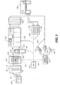
- the photofinishing apparatus shown constitutes the major components of a photofinishing laboratory.
- the apparatus includes a splicer 100 which splices exposed light sensitive filmstrips which have been removed from their respective light tight cassettes 10, together into a film web 19 by attaching them end to end.
- Each filmstrip is normally regarded as a single customer order (although it is possible for a single customer order to include more than one filmstrip), and carries a plurality of exposed latent images.
- Film web 19 is placed on a reel 18.
- the film web 19 on reel 18 is then chemically developed through a series of steps in a chemical developer 20, in a known manner, to yield permanent visible optical images on film web 19.
- Each filmstrip will typically be a negative type filmstrip yielding negative type images on a transparent base after developing by chemical developer 20, although the filmstrips and developer 20 could be of a kind which produce positive transparencies (that is, slides) also in a known manner.
- a developed film web 19 exiting developer 20 is then passed to a high speed scanner 102 which operates at 200 images/minute or greater.
- Scanner 102 includes a film gate at which each image of the film can be successively positioned to receive light from a light source, which then passes through each image and a subsequent lens system to fall upon an image sensor.
- the image sensor can be a line sensor or area array sensor.
- Appropriate electronics (including an analog to digital converter) in the scanner 102 convert the sensor signals to digital signals.
- the output of scanner 102 then, is a series of digital image signals corresponding to each image on the film.
- Scanner 102 acts as a first capture device which provides the images in the form of digital image signals.
- Scanner 102 should be capable of scanning images with a reasonably high resolution, such as at least 400 x 200 pixels over the area of images (such as at least 600 x 400 pixels) and preferably at least 1000 x 1500 pixels (and most preferably at least 2000 x 3000 pixels). Scanners of the foregoing type are well known in the art and need not be described further. Scanner 102 includes intermediate storage 103 for the digital images, in the form of magnetic disk drives or any other suitable read/write storage device.
- Scanner 102 is also fitted with a film code reader 103, which may either be an optical or a magnetic code reader capable of reading optical or magnetic codes on a film.
- a film code reader 103 may either be an optical or a magnetic code reader capable of reading optical or magnetic codes on a film.
- codes may, for example, be customer provided requests associated with particular specified images (such as one or more identified images or all of the images on a customer filmstrip) for specific image product or image services.
- such codes could indicate that the customer wants a panoramic print of a specified image associated with the code, or wants a particular image product incorporating a specified image associated with a code (for example, or T-shirt or cup), or wants specified color modifications to a particular image (for example, indicating an order for a black and white print from a specified image).
- the codes could also indicate that the customer wants another particular type of image product (for example, a portable optical or magnetic disk) or image service (for example, an upload of a corresponding image signal to a remote location) with one or more specified images associated with the code.
- image signals are passed over communication network connection 104 from scanner 102 to an Image Data Manager (“IDM”) 170.
- IDM Image Data Manager
- Codes read by code reader 103 may also be passed over network 104 to IDM 170.
- IDM 170 is also connected through network 104 with an image preview station 120 and a number of output devices in the form of a printers 130, 132, 134. IDM 170 is further connected through network 104 to other output devices in the form of a media station 111, which provides image signal outputs on magnetic disks 114, optical disks 112, or over a communication channel 113 (which may be wire, fiber optic cable, or wireless) to the Internet.
- Image preview station 120 includes a processor 122 and a connected monitor 124 (sometimes referenced as a screen) and operator input device 126 in the form of a keyboard and/or mouse or other suitable operator input device. Processor 122 is optional in the sense that functions performed by it can be performed by IDM 170.
- Monitor 124 may, for example, be a CRT or LCD screen.
- Operator input device 126 also allows an operator to input codes corresponding to customer requests for particular image products or image services which may be found as printing on an envelope which carried the customer filmstrip. The request will be associated with one or more particular images by identifying those images, usually by number, on the envelope. When the operator inputs such information through input device 126 it becomes a customer code request associated with one or more particular identified images. Alternatively, a separate operator input device (not shown) may be used for such a purpose.
- Preview station 120 provides its output, back to IDM 170 through network 104 although it could also provide its output to printer 130 through a second network 127.
- Each of printers 130, 132, 134 may, for example, be a high speed color laser printer which prints digital image signals received from IDM 170 (or from preview station 120) onto a light sensitive layer of a photographic paper web.
- any or all of the printers 130, 132, 134 could be inkjet, thermal or any other suitable image printer.
- the exposed photographic paper from printer 130 is then developed in color paper developer 140 to yield fixed images on the paper, in a known manner.
- the web, following developing in developer 140 is transported to a finishing station 160 to which the scanned film web 19 on reel 18 is also sent.
- a web or individual printed sheets from printers 132, 134 are also transported to finishing station 160.
- any paper webs are cut into individual image prints, each scanned filmstrip is cut into strips (for 35mm film) or reinserted into a cassettes (for Advanced Photo System film), and any prints from printers 130, 132, 134 are mated with the corresponding customer film and any optical or magnetic disks 112, 114 to complete the customer's order.
- image signals may be obtained from additional or other devices which provide the images:
- image signals might be provided to IDM 170 by being read from floppy magnetic disks 114, optical disks 112 or received from the Internet over communication channel 113.
- image signals can be handled by IDM 170 and preview station 120 in the same manner as image signals received from scanned photographic media.
- media station 111 is a media input and output station capable of both reading and writing to disks 112, 114 and transmitting or receiving over communication channel 113.
- All of the components of FIG. 1 may be individual components, as illustrated, all located at least in the same building or even the same room of a building. This will be the typical configuration of a large wholesale photofinishing laboratory. On the other hand, in situations where images are handled at a lower volumes over a given time, such as in a retail store outlet, some or all of the components of FIG. 1 may be located within a single housing occupying an area of only about 1 to 10 square meters, sometimes referred to as a "minilab" or similar terms.
- IDM 170 includes a processor which acts as a render manager 208.
- IDM 170 further includes first, second and third queue memories 210, 212, 214, respectively, which respectively act as first, second, and third image queues.
- IDM 170 further has five image processors which act as renderers 220, 224, 226, 228, and 230.
- Each of the queue memories and renderers are typically separate physical devices, with each being capable of operating independently of the others.
- each queue memory 210, 212, 214 has at least one corresponding image renderer which receives images for rendering only from that one queue memory.
- the components of IDM 170 are all interconnected over the same network 104 as illustrated in FIG.
- IDM 170 may be housed in a single housing as represented schematically in FIG. 1 , or may in whole or in part be physically separated and interconnected by the network 104 or another suitable network.
- Image renderers 220, 224, 226 communicate rendered images to printer 130. This communication can also be over the same network 104, although separate physical connections could be provided from a given renderer to its corresponding printer(s).
- Renderers 226, 228 communicate rendered images to printer 132, while renderer 230 communicates rendered images to printer 134.
- renderer 226 acts as a same rendering device which receives images from different queues 210, 212 and communicates such images to printers 132, 134, respectively.
- Renderers 220, 224, 226 then, are capable of rendering images received from queue memory 210 into a first format suitable for printer 130.
- Renderer 228 as well as renderer 226 are both capable of rendering images from queue memory 212 into a format suitable for printer 132, while renderer 230 is capable of rendering images from queue 214 into a format suitable for printer 134.
- image queue 210 communicates images to multiple renderers operating in parallel (renders 220, 224 and in part renderer 226), while renderer 226 also communicates with multiple queue memories.
- Image renderers 220, 224, 228, 230 are "dedicated” in that they each receive image signals only from a single queue memory (queue memory 210 in the case of image renderers 220, 224; queue memory 212 in the case of image renderer 228; and queue memory 214 in the case of image renderer 230).
- image renderer 226 is not dedicated to one queue memory.
- the image formats rendered by each renderer for images received from its communicating queue memory can be considered a format "associated" with that queue memory.
- the image formats produced by renderers 220, 224 (and renderer 226 for image signals received from queue memory 210) for printer 130 is associated with queue memory 210.
- This association may be somewhat arbitrary in the sense that, when the components of FIG. 2 are all communicating over the same network 104, the initial designation of which queue memory is associated with which renderer(s) can be made by render manager 208 (such as by render manager 208 instructing a given renderer to pull image signals for rendering only from one or more of the queue memories).
- Additional queue memories and renderers may also be used, for example to render images to be output by media station 111 onto magnetic disks 114, optical disks 112, or over a communication channel 113.
- the film code data or input received from operator input operator input device 126 provide information on customer requested outputs for each image (for example, for a given image the customer may want a poster sized image and a T-shirt with the image).
- image signals and associated customer requests may be received from media station 111.
- Render manager 208 receives the customer requests for products or services incorporating associated images, from code reader 103, operator input device 126, or from data received at media station 111 from magnetic disks 114, optical disks 112, or over communication channel 113. Render manager 208 directs each image signal into the appropriate one or more queue memories 210, 212, 214 based on the customer's product or service request associated with that image. Note that render manager 208 can direct the image signals to the appropriate queue memory in a number of ways. For example, render manager 208 can actually receive the image data itself also and, based on the associated customer requests, simply communicate the image data to the appropriate one or more queue memories 210, 212, 214.
- render manager 208 can direct the image signal to the appropriate queue by simply receiving a customer request associated with a given image along with an identification of the image with which such request is associated, and forwarding the identification of that image (including storage location on the network 104) to the appropriate one or more queue memories 210, 212, 214.
- Queue memories 210, 212, 214 can then issue a request over network 104 to the device where the required image data is stored, to receive the actual image data for each image identification it has received from render manager 208.
- the actual image data in this case can be stored at other storage devices (not shown), such as a memory within scanner 102, until requested by one or more of the image queues.
- the configuration of having multiple renderers communicating with queue memory 210 allows for the rendering of a larger number of images per unit time (or rendering into a format requiring more computations, or both), than is possible using just one renderer communicating with a queue memory.
- the arrangement of FIG. 2 may be used when it is known that customers will order far more image products of a type produced by printer 130 than printer 134.
- the use of at least one renderer (such as renderer 226) which communicates with more than one image queue allows for more flexibility where it is expected that the ratio of different image products or services, may vary over time.
- Such a renderer 226 may receive image signals from multiple queue memories 210, 212 with which it communicates, based on various routines.
- it may receive image signals sequentially from the queue memories (for example, one image from queue memory 210, then one from queue memory 212, then another from queue memory 210, and so on).
- it may receive images from one of the queue memories such as queue memory 210, until that queue memory is empty, then receive images from the next queue memory 212 until that queue memory is empty, then receive image signals from queue memory 210 again until empty, and so on.
- a time based routine may be used, or any combination of the foregoing routines used.
- Preview station 120 allows an operator to preview images before printing and provide operator input on image corrections that may be required. Images shown for operator input may be limited to those which IDM 170 determines have image characteristics which make it unlikely IDM 170 would be able to simply automatically perform corrections and/or modifications based solely on its own algorithms. Such a preview station and its operation is described in EP-0933 679-A filed January 18, 1999 , entitled PHOTOGRAPHIC PROCESSING APPARATUS AND METHOD, by T. Murray et al. (Kodak Docket No. 77374/GMS), assigned to the same assignee as the present application.
Landscapes
- Physics & Mathematics (AREA)
- General Physics & Mathematics (AREA)
- Facsimiles In General (AREA)
- Projection-Type Copiers In General (AREA)
Applications Claiming Priority (2)
| Application Number | Priority Date | Filing Date | Title |
|---|---|---|---|
| US127653 | 1998-07-31 | ||
| US09/127,653 US6215559B1 (en) | 1998-07-31 | 1998-07-31 | Image queing in photofinishing |
Publications (2)
| Publication Number | Publication Date |
|---|---|
| EP0977084A1 EP0977084A1 (en) | 2000-02-02 |
| EP0977084B1 true EP0977084B1 (en) | 2013-07-03 |
Family
ID=22431198
Family Applications (1)
| Application Number | Title | Priority Date | Filing Date |
|---|---|---|---|
| EP99202370.5A Expired - Lifetime EP0977084B1 (en) | 1998-07-31 | 1999-07-19 | Customer images processing method and apparatus |
Country Status (3)
| Country | Link |
|---|---|
| US (1) | US6215559B1 (enExample) |
| EP (1) | EP0977084B1 (enExample) |
| JP (1) | JP2000056397A (enExample) |
Families Citing this family (18)
| Publication number | Priority date | Publication date | Assignee | Title |
|---|---|---|---|---|
| US6373585B1 (en) * | 1998-08-26 | 2002-04-16 | International Business Machines Corporation | Load balancing for processing a queue of print jobs |
| US6839803B1 (en) * | 1999-10-27 | 2005-01-04 | Shutterfly, Inc. | Multi-tier data storage system |
| US6442573B1 (en) * | 1999-12-10 | 2002-08-27 | Ceiva Logic, Inc. | Method and apparatus for distributing picture mail to a frame device community |
| JP2001290627A (ja) | 2000-02-04 | 2001-10-19 | Fuji Photo Film Co Ltd | プリントシステム、プリント方法および装置並びに注文振り分け方法および装置 |
| EP1137245A3 (en) * | 2000-03-17 | 2003-04-02 | GRETAG IMAGING Trading AG | Photo finishing system with ink-jet printer |
| EP1134963A3 (en) * | 2000-03-17 | 2003-07-23 | GRETAG IMAGING Trading AG | System for printing digitised images |
| US7062527B1 (en) | 2000-04-19 | 2006-06-13 | Silicon Graphics, Inc. | Management and scheduling of a distributed rendering method and system |
| US7092983B1 (en) | 2000-04-19 | 2006-08-15 | Silicon Graphics, Inc. | Method and system for secure remote distributed rendering |
| US7783695B1 (en) * | 2000-04-19 | 2010-08-24 | Graphics Properties Holdings, Inc. | Method and system for distributed rendering |
| JP2001337995A (ja) * | 2000-05-26 | 2001-12-07 | Noritsu Koki Co Ltd | 画像管理装置および方法、ならびに、画像データを管理するプログラムを記録したコンピュータ読み取り可能な記録媒体 |
| JP4038007B2 (ja) * | 2000-08-29 | 2008-01-23 | 富士フイルム株式会社 | プリントシステム |
| JP4135081B2 (ja) * | 2003-02-28 | 2008-08-20 | ノーリツ鋼機株式会社 | 画像データ処理システム |
| US20050016667A1 (en) * | 2003-07-23 | 2005-01-27 | Mark Dwight | Method of manufacturing lampshades |
| US20060041719A1 (en) * | 2004-08-18 | 2006-02-23 | Chui Jimmy P F | Multi-tier data storage system |
| US7869079B2 (en) * | 2004-09-20 | 2011-01-11 | Electronics For Imaging, Inc. | Methods and apparatus for print job submission |
| US9483877B2 (en) | 2011-04-11 | 2016-11-01 | Cimpress Schweiz Gmbh | Method and system for personalizing images rendered in scenes for personalized customer experience |
| JP5813619B2 (ja) * | 2012-11-22 | 2015-11-17 | 京セラドキュメントソリューションズ株式会社 | 画像形成装置 |
| US10402930B2 (en) * | 2013-10-14 | 2019-09-03 | Microsoft Technology Licensing, Llc | Management of graphics processing units in a cloud platform |
Family Cites Families (18)
| Publication number | Priority date | Publication date | Assignee | Title |
|---|---|---|---|---|
| US4065661A (en) | 1975-04-26 | 1977-12-27 | Eastman Kodak Company | Photofinishing apparatus |
| US5012409A (en) * | 1988-03-10 | 1991-04-30 | Fletcher Mitchell S | Operating system for a multi-tasking operating environment |
| US5402361A (en) | 1991-04-18 | 1995-03-28 | X-Rite, Incorporated | Apparatus for method for logging, storing, and redirection of process related non-densitometric data generated by color processing equipment for use by an off site host computer |
| US5179637A (en) | 1991-12-02 | 1993-01-12 | Eastman Kodak Company | Method and apparatus for distributing print jobs among a network of image processors and print engines |
| US5652643A (en) | 1992-03-17 | 1997-07-29 | Sony Corporation | Photographic and video image system |
| US5535322A (en) | 1992-10-27 | 1996-07-09 | International Business Machines Corporation | Data processing system with improved work flow system and method |
| US5287194A (en) | 1992-11-25 | 1994-02-15 | Xerox Corporation | Distributed printing |
| IL106792A (en) | 1993-08-24 | 1998-02-08 | Scitex Corp Ltd | System for planning and making illustrations |
| US5454107A (en) * | 1993-11-30 | 1995-09-26 | Vlsi Technologies | Cache memory support in an integrated memory system |
| US5596416A (en) | 1994-01-13 | 1997-01-21 | T/R Systems | Multiple printer module electrophotographic printing device |
| US5576794A (en) | 1994-05-12 | 1996-11-19 | Eastman Kodak Company | Random batch photofinishing |
| US5619624A (en) | 1994-05-20 | 1997-04-08 | Management Graphics, Inc. | Apparatus for selecting a rasterizer processing order for a plurality of graphic image files |
| US5612796A (en) | 1995-02-17 | 1997-03-18 | Eastman Kodak Company | Photographic film preparation workstation |
| US5664253A (en) * | 1995-09-12 | 1997-09-02 | Eastman Kodak Company | Stand alone photofinishing apparatus |
| US5631740A (en) | 1995-11-28 | 1997-05-20 | Xerox Corporation | Transducers with constraints model for print scheduling |
| JPH09265141A (ja) * | 1996-03-27 | 1997-10-07 | Fuji Photo Film Co Ltd | 混在プリント方法及びシステム |
| US5995721A (en) * | 1996-10-18 | 1999-11-30 | Xerox Corporation | Distributed printing system |
| JPH10150541A (ja) * | 1996-11-20 | 1998-06-02 | Fuji Photo Film Co Ltd | フォトフィニッシングシステム |
-
1998
- 1998-07-31 US US09/127,653 patent/US6215559B1/en not_active Expired - Lifetime
-
1999
- 1999-07-19 EP EP99202370.5A patent/EP0977084B1/en not_active Expired - Lifetime
- 1999-07-27 JP JP11212164A patent/JP2000056397A/ja active Pending
Also Published As
| Publication number | Publication date |
|---|---|
| JP2000056397A (ja) | 2000-02-25 |
| EP0977084A1 (en) | 2000-02-02 |
| US6215559B1 (en) | 2001-04-10 |
Similar Documents
| Publication | Publication Date | Title |
|---|---|---|
| US6157436A (en) | Image printing | |
| EP0977084B1 (en) | Customer images processing method and apparatus | |
| US5400152A (en) | High speed index printer | |
| US6353487B1 (en) | System and method for selecting photographic images using index prints | |
| US6483570B1 (en) | Image processing | |
| EP0672949B1 (en) | Film information communication apparatus, film information printing apparatus, information processing apparatus and index printer | |
| US5455648A (en) | Film holder for storing processed photographic film | |
| EP0969322B1 (en) | Image movement in a photographic laboratory | |
| EP0727693A1 (en) | Photofinishing system | |
| EP1137247A2 (en) | Photofinishing system and method | |
| US6288771B1 (en) | Method and device for producing positive images | |
| CA2348610A1 (en) | Photo finishing system with ink-jet printer | |
| US6890690B2 (en) | Photographic article | |
| US5623710A (en) | Presentation apparatus for photographic data | |
| US20060250666A1 (en) | Automated image processing system and method | |
| JPH1013589A (ja) | 写真プリントシステム | |
| EP0341077A2 (en) | Film holder for storing processed photographic film | |
| US20020033893A1 (en) | Method and apparatus for generating images |
Legal Events
| Date | Code | Title | Description |
|---|---|---|---|
| PUAI | Public reference made under article 153(3) epc to a published international application that has entered the european phase |
Free format text: ORIGINAL CODE: 0009012 |
|
| AK | Designated contracting states |
Kind code of ref document: A1 Designated state(s): DE FR GB |
|
| AX | Request for extension of the european patent |
Free format text: AL;LT;LV;MK;RO;SI |
|
| 17P | Request for examination filed |
Effective date: 20000711 |
|
| AKX | Designation fees paid |
Free format text: DE FR GB |
|
| 17Q | First examination report despatched |
Effective date: 20031107 |
|
| GRAP | Despatch of communication of intention to grant a patent |
Free format text: ORIGINAL CODE: EPIDOSNIGR1 |
|
| RAP1 | Party data changed (applicant data changed or rights of an application transferred) |
Owner name: INTELLECTUAL VENTURES FUND 83 LLC |
|
| GRAS | Grant fee paid |
Free format text: ORIGINAL CODE: EPIDOSNIGR3 |
|
| GRAA | (expected) grant |
Free format text: ORIGINAL CODE: 0009210 |
|
| AK | Designated contracting states |
Kind code of ref document: B1 Designated state(s): DE FR GB |
|
| REG | Reference to a national code |
Ref country code: GB Ref legal event code: FG4D |
|
| REG | Reference to a national code |
Ref country code: DE Ref legal event code: R096 Ref document number: 69944808 Country of ref document: DE Effective date: 20130829 |
|
| PLBE | No opposition filed within time limit |
Free format text: ORIGINAL CODE: 0009261 |
|
| STAA | Information on the status of an ep patent application or granted ep patent |
Free format text: STATUS: NO OPPOSITION FILED WITHIN TIME LIMIT |
|
| 26N | No opposition filed |
Effective date: 20140404 |
|
| REG | Reference to a national code |
Ref country code: DE Ref legal event code: R097 Ref document number: 69944808 Country of ref document: DE Effective date: 20140404 |
|
| REG | Reference to a national code |
Ref country code: FR Ref legal event code: PLFP Year of fee payment: 18 |
|
| PGFP | Annual fee paid to national office [announced via postgrant information from national office to epo] |
Ref country code: GB Payment date: 20160624 Year of fee payment: 18 |
|
| PGFP | Annual fee paid to national office [announced via postgrant information from national office to epo] |
Ref country code: FR Payment date: 20160621 Year of fee payment: 18 |
|
| PGFP | Annual fee paid to national office [announced via postgrant information from national office to epo] |
Ref country code: DE Payment date: 20160801 Year of fee payment: 18 |
|
| REG | Reference to a national code |
Ref country code: DE Ref legal event code: R119 Ref document number: 69944808 Country of ref document: DE |
|
| GBPC | Gb: european patent ceased through non-payment of renewal fee |
Effective date: 20170719 |
|
| REG | Reference to a national code |
Ref country code: FR Ref legal event code: ST Effective date: 20180330 |
|
| PG25 | Lapsed in a contracting state [announced via postgrant information from national office to epo] |
Ref country code: GB Free format text: LAPSE BECAUSE OF NON-PAYMENT OF DUE FEES Effective date: 20170719 Ref country code: DE Free format text: LAPSE BECAUSE OF NON-PAYMENT OF DUE FEES Effective date: 20180201 |
|
| PG25 | Lapsed in a contracting state [announced via postgrant information from national office to epo] |
Ref country code: FR Free format text: LAPSE BECAUSE OF NON-PAYMENT OF DUE FEES Effective date: 20170731 |