EP0976557B1 - Druckvorrichtung unter Verwendung von hydrophilen/hydrophoben Polymeren - Google Patents
Druckvorrichtung unter Verwendung von hydrophilen/hydrophoben Polymeren Download PDFInfo
- Publication number
- EP0976557B1 EP0976557B1 EP99420160A EP99420160A EP0976557B1 EP 0976557 B1 EP0976557 B1 EP 0976557B1 EP 99420160 A EP99420160 A EP 99420160A EP 99420160 A EP99420160 A EP 99420160A EP 0976557 B1 EP0976557 B1 EP 0976557B1
- Authority
- EP
- European Patent Office
- Prior art keywords
- polymer element
- state
- event
- hydrophilic
- fluid
- Prior art date
- Legal status (The legal status is an assumption and is not a legal conclusion. Google has not performed a legal analysis and makes no representation as to the accuracy of the status listed.)
- Expired - Lifetime
Links
- 238000007639 printing Methods 0.000 title claims description 30
- 229920001477 hydrophilic polymer Polymers 0.000 title 1
- 229920001600 hydrophobic polymer Polymers 0.000 title 1
- 229920000642 polymer Polymers 0.000 claims description 134
- 239000012530 fluid Substances 0.000 claims description 62
- 230000002209 hydrophobic effect Effects 0.000 claims description 28
- 238000000034 method Methods 0.000 claims description 13
- 239000000463 material Substances 0.000 claims description 11
- 238000001816 cooling Methods 0.000 claims description 5
- 230000008569 process Effects 0.000 claims description 4
- -1 polyethylene Polymers 0.000 description 9
- 238000010438 heat treatment Methods 0.000 description 7
- 238000005516 engineering process Methods 0.000 description 6
- 230000007704 transition Effects 0.000 description 6
- 229920003213 poly(N-isopropyl acrylamide) Polymers 0.000 description 4
- 239000000126 substance Substances 0.000 description 4
- 230000017525 heat dissipation Effects 0.000 description 3
- 239000011810 insulating material Substances 0.000 description 3
- 230000003287 optical effect Effects 0.000 description 3
- 230000008901 benefit Effects 0.000 description 2
- 230000015572 biosynthetic process Effects 0.000 description 2
- 125000001165 hydrophobic group Chemical group 0.000 description 2
- 239000000178 monomer Substances 0.000 description 2
- 239000000049 pigment Substances 0.000 description 2
- HRPVXLWXLXDGHG-UHFFFAOYSA-N Acrylamide Chemical compound NC(=O)C=C HRPVXLWXLXDGHG-UHFFFAOYSA-N 0.000 description 1
- 239000004698 Polyethylene Substances 0.000 description 1
- 230000009471 action Effects 0.000 description 1
- 230000008859 change Effects 0.000 description 1
- 238000009792 diffusion process Methods 0.000 description 1
- 239000000975 dye Substances 0.000 description 1
- 230000000694 effects Effects 0.000 description 1
- 230000005684 electric field Effects 0.000 description 1
- 230000005686 electrostatic field Effects 0.000 description 1
- 230000001747 exhibiting effect Effects 0.000 description 1
- 230000006355 external stress Effects 0.000 description 1
- 150000002334 glycols Chemical class 0.000 description 1
- 238000005470 impregnation Methods 0.000 description 1
- 238000007641 inkjet printing Methods 0.000 description 1
- 229910052500 inorganic mineral Inorganic materials 0.000 description 1
- 238000004519 manufacturing process Methods 0.000 description 1
- FQPSGWSUVKBHSU-UHFFFAOYSA-N methacrylamide Chemical compound CC(=C)C(N)=O FQPSGWSUVKBHSU-UHFFFAOYSA-N 0.000 description 1
- 239000011707 mineral Substances 0.000 description 1
- 238000012986 modification Methods 0.000 description 1
- 230000004048 modification Effects 0.000 description 1
- 229920000620 organic polymer Polymers 0.000 description 1
- 229920000573 polyethylene Polymers 0.000 description 1
- 230000004044 response Effects 0.000 description 1
- 229910052710 silicon Inorganic materials 0.000 description 1
- 239000010703 silicon Substances 0.000 description 1
- 239000004094 surface-active agent Substances 0.000 description 1
- 238000003786 synthesis reaction Methods 0.000 description 1
- 125000000391 vinyl group Chemical group [H]C([*])=C([H])[H] 0.000 description 1
- 229920002554 vinyl polymer Polymers 0.000 description 1
Images


Classifications
-
- B—PERFORMING OPERATIONS; TRANSPORTING
- B41—PRINTING; LINING MACHINES; TYPEWRITERS; STAMPS
- B41J—TYPEWRITERS; SELECTIVE PRINTING MECHANISMS, i.e. MECHANISMS PRINTING OTHERWISE THAN FROM A FORME; CORRECTION OF TYPOGRAPHICAL ERRORS
- B41J2/00—Typewriters or selective printing mechanisms characterised by the printing or marking process for which they are designed
- B41J2/005—Typewriters or selective printing mechanisms characterised by the printing or marking process for which they are designed characterised by bringing liquid or particles selectively into contact with a printing material
Definitions
- the present invention relates to a printing device, specifically, to an ink jet printing device.
- the present invention also relates to a printing process using such a device.
- the object of almost all the printing technologies developed today is to produce high quality copies as fast as possible, at the lowest possible cost.
- the printing process in technologies relevant to thermal ink jet heads, conventionally has two steps.
- the first step consists in forming an ink drop and the second step consists in ejecting the ink drop from the ink jet head towards a receiving support.
- the formation of the ink drop requires raising the ink found in a channel to a high temperature in a very short time. This method requires heat in the volume of the ink jet head itself, which must then be dissipated.
- the drop can be ejected by different techniques, for example by the application of an electrostatic field.
- One of the ink jet technologies in order to achieve fast printing consists in the use of a plurality of nozzles on the head surface that can eject ink drops in order to print a larger number of points in parallel on the receiving support.
- the number of nozzles on the head surface is restricted either because of problems related to heat dissipation in methods that consist in carrying high temperature ink as in the technologies developed by Canon and Hewlett Packard, or because of problems related to dimensional instability due to the vibrations caused by the use of piezoelectric technologies like those developed by Seiko-Epson.
- print devices have to be developed containing micro-elements that are generally very costly.
- EP 0 940 255 describes a printing inkjet head comprising means for feeding printing fluid, one channel terminated by a nozzle and means for moving the printing fluid that comprise polymer whose hydrophilic or hydrophobic properties can be selected under the action of an external stress.
- EP 0 940 255 falls under Article 54(3) EPC.
- the present invention proposes the provision of a new printing device using polymers exhibiting specific properties.
- the present invention relates to a printing device comprising a polymer element capable of switching from an initial state to a final state when subjected to an event, the initial state and the final state being selected from an hydrophilic state and an hydrophobic state provided that the initial state differs form the second state, wherein said polymer element is impregnated with a print fluid selected to be hydrophilic when the polymer element in the initial state is hydrophilic, or hydrophobic when the polymer element is in the initial state hydrophobic, and a controller adapted to generate the event producing the switch on a localized zone of the polymer element and on an internal zone delimited by the localized zone in order to form a fluid drop at the surface of the polymer element.
- the present invention also relates to a method that comprises impregnating with a printing fluid a polymer element capable of switching from an initial state to a final state when subjected to an event, the initial state and the final state being selected from an hydrophilic state and an hydrophobic state provided that the initial state differs form the final state, wherein the print fluid is selected to be hydrophilic when the polymer element in the initial state is hydrophilic, or hydrophobic when the polymer element is in the initial state hydrophobic, generating an event for producing the switch of the polymer element on a localized zone and on an internal zone delimited by the localized zone in order to form at the polymer surface a printing fluid drop, and contacting the drop fluid with a printing receiver element.
- the present invention has the advantage of forming a heat dissipating ink jet head.
- the ink jet head is created at the moment of use and for the duration of this use.
- the printing device of the invention allows printing a low temperature, avoiding any problems relating to the heat dissipation.
- the invention device eliminates any need for complex mechanics such as those used in known ink jet heads.
- the device of the present invention has a low manufacturing cost.
- the polymer element of the invention can be a polymer element that is initially in a hydrophilic state and switches to turn into a hydrophobic state when subjected to an event producing the switch.
- the polymer element of the invention can also be a polymer element that is initially in a hydrophobic state and switches to turn into a hydrophilic state when subjected to the event producing the switch. These polymer elements are also able to switch from the final state to the initial stage when the event is released.
- Polymer elements that can switch from an initial state to a final state when subjected to an event are well known in the art as switchable polymer.
- the event can be any event adapted to produce the switch of the polymer element from an initial state to a final state.
- the event that can be used is determined by the nature and the initial state of the polymer element.
- the event can be for example an optical event, a thermal event, electrical event or a chemical event.
- the polymer element of the invention is a thermo-reversible polymer.
- These elements are polymer elements capable of switching from an initial state to a final state when subjected to a thermal event such as heating or cooling, depending on the nature and the initial state of the polymer element. Conventionally, these polymers exhibit a phase transition temperature Tg.
- the polymer element useful in the device of the invention is a polymer element initially in the hydrophilic state switching from a hydrophilic state to a hydrophilic state when the element is heated above its Tg, and which reverse back to the hydrophobic state when the heating is released and the polymer element returns at a temperature below Tg.
- the polymer can return to the hydrophilic state by simple heat dissipation.
- the polymer element of the invention is a thermo-reversible polymer that is hydrophilic at ambient temperature, and has a phase transition temperature between 20 and 100°C, preferably between 30 and 70°C.
- Thermo-reversible polymers that can be used in the present device are organic polymers such as those described in PCT Patent Application WO 91/15526. These are polymers that have a hydrophilic group and a hydrophobic group, the hydrophilic group being a water-soluble ionic polymerizable vinyl monomer, and the hydrophobic group comprising an acrylamide or methacrylamide monomer.
- polysilylamine a polymer that switches from the initial state to a final state fast, for example poly(N-isopropylacrylamide).
- Poly(N-isopropylacrylamide) has a temperature Tg of about 32°. When this polymer is at a temperature less than 32°, it is hydrophilic. When it exceeds 32°, it becomes hydrophobic.
- the hydrophilic/hydrophobic phase transition temperature of a polymer can be modified by different means.
- adding a surfactant to the print fluid is known to increase the phase transition temperature. This technique is described in the publication, Langmuir, 1995, Volume 11, No. 7, pages 2493-2495.
- the phase transition temperature Tg of poly(N-isopropylacrylamide) can be modified from 32°C to 90°C.
- hydrophilic/hydrophobic change of state of some polymers causes the polymer's volume to vary. According to the applications, it can be an advantage to be free of volume variations. Therefore, known techniques such as those described in Polymer Communications, "Synthesis of fast response, temperature-sensitive poly(N-isopropylacrylamide) gel", can be used.
- the polymer element of the present device can be self-supporting. It can also be supported by a support.
- the support has to transmit the event producing the switch. For example, when the event producing the switch is heating, the support need to be able to transfer the heat to the polymer element.
- the controller of the invention can be any controller adapted to generate an event producing the switch of the polymer element from an initial state to a final state.
- the controller can be adapted to generate an optical event, a thermal event, electrical event or a chemical event, depending on the nature of the polymer element.
- the controller is adapted to generate the event producing the switch of the polymer element on a localized zone delimiting an internal zone, and then on the internal zone.
- the localized zone can be a continuous zone or a discontinuous zone.
- Examples of the controller producing the switch can be heating/cooling means, a laser, electrical means, chemical means such as means to alter the pH, means to alter the ionic force, or even mechanical means such as means to alter the pressure.
- the controller is adapted to generate a thermal event.
- Heating means is for example an element comprising a thin layer of polycrystal silicon in which a current is made to flow adapted to generate a quantity of heat allowing the polymer to exceed its phase transition temperature for switching from a initial state to a final state.
- the controller is a laser beam and the polymer element is a thermo-reversible polymer element absorbing the laser's wavelength, typically 670 nm.
- One or more controller adapted to generate the event producing the switch of the polymer element on the localized zone A and then the internal zone B can be used.
- the controller is a laser beam
- two independent laser beams can be used to switch the localized zone and then the internal zone B from the initial to the final second state.
- a single laser beam can also be used, whose beam is modulated to give minimum energy to the center of the beam and maximum to the sides.
- the device of the invention can further contain an additional controller adapted to generate an appropriate event.
- This additional controller can be any controller adapted to generate the event producing the switch of the polymer element from the final state to the initial state.
- the additional controller can be adapted to generate an optical event, a thermal event, electrical event or a chemical event, depending on the nature of the polymer element.
- the additional controller will be means for cooling the polymer element, for example a fan or a pelletier effect device.
- the device of the invention can also include means for feeding a fluid into the polymer element in order to maintain a constant impregnation of the polymer element with the fluid.
- a fluid into the polymer element in order to maintain a constant impregnation of the polymer element with the fluid.
- This can be carried out by any known technique, for example with a fluid reservoir connected to the polymer, or for example by capillary diffusion.
- the fluid can be any known printing fluid containing organic or mineral pigments.
- the device of the invention can further include means for positioning a fluid receiving material.
- the fluid receiving material that can be any material known in the printing domain, for example paper, whether coated or not, in sheet or roll form.
- Figure 1A shows a representation of the device of the invention which comprises a polymer element 10 impregnated with a fluid, a fluid receiving material 16, the fluid receiving material 16 being positioned in the device by means of positioning means 18, a controller 12, an additional controller 20 and means such as a reservoir 22 for feeding a fluid in the polymer element 10.
- Figure 1B when a localized zone A of the polymer element in an initial state is subjected to a suitable event by means of the controller 12, the zone A of the polymer element switches from the initial state to the final state.
- the fluid initially present in the zone A tends to be pushed out of the zone A to a zone of the polymer element 10 still in the initial state, as shown by the arrows in Figure 1B.
- the fluid is pushed into an internal zone B delimited by the zone A. It is thus obtained a localized zone A in the final state and a internal zone B in the initial state, impregnated with fluid.
- zone B switches from the initial state to the final state, thereby moving the fluid contained in zone B outside the zone B toward the polymer surface opposed to the surface subjected to the event to form a fluid drop 14 at the surface of the polymer element.
- a print is then obtained by contacting the fluid drop 14 at the surface of the zone B of the polymer element with the fluid receiving material 16.
- the fluid drop 14 can also be ejected from the surface to the fluid receiving material.
- the drop can be ejected for example by the application of an electric field, or by any known techniques.
- the zone A can be continuous or discontinuous.
- Figure 2A shows an example of a polymer element after subjecting a localized continuous zone A to the event.
- Figure 2B shows the same polymer element after subjecting the internal zone B to the event.
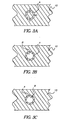
- Figure 3A shows an example of a polymer element after subjecting a localized discontinuous zone A to the event.
- zone A is discontinuous
- the fluid contained in the internal zone B can spread outside this zone, as shown by the arrows in Figure 3A.
- the fluid present in the internal zone B is not completely isolated from the part of the polymer element in the initial state. Thus it can spread into the rest of the polymer still in the initial state.
- it can be desirable to delay the application of the event to zone B until a desired quantity of fluid is released from the zone B to zone A.
- Figure 3B shows the same polymer element after subjecting the internal zone B to the event, when the zone A is a discontinuous localized zone.
- the event is released from the localized zone A and the internal zone B now in the final state, for example by deactivating the controller 12.
- the localized zone A and the internal zone B of the polymer element are then able to switch from the final state to the initial state.
- the polymer is thus able to be impregnated again with the fluid through the reservoir 22 for feeding the fluid to the polymer element 10.
- the switch from the final state to the initial state of the localized zone A and the internal zone B can also be expedited by subjecting the localized zone A and the internal zone B of the polymer element to a suitable event generated by the additional controller 20.
- the device of the present invention can comprise a plurality of polymer elements as described above used successively.
- the device can comprise means to move the plurality of polymer elements.
- the device of the invention can also comprise a continuous polymer element sheet, drawn by rollers.
- the polymer elements can be associated to form a cylinder. Rotating the cylinder allows the position of the various polymer elements to be simply changed in relation to the controller 12. The speed of rotation of the cylinder will be selected according to the suitable print speed and the time the polymer element switches from the final state to the initial state, when subjected to the suitable event..
- the device of the invention can also comprise polymer elements 10 each separated from the others by a fluid insulating material 24. In that case, the entire unit is subjected to the event, the fluid insulating material 24 avoiding the spread of the fluid.
- the fluid useful in the device of the invention is a print fluid, for example a hydrophilic or hydrophobic printing ink, containing pigments or organic dyes.
- the fluid will be selected to be able to impregnate the polymer element.
- the fluid will be a hydrophilic printing fluid on order to be fed to the polymer element.
- the fluid still hydrophilic tends to spread out of the hydrophobic zone, thereby forming the fluid drop on the surface of the hydrophobic zone of the polymer element.
- the printing fluid will be an hydrophobic printing fluid.
Landscapes
- Ink Jet (AREA)
- Micromachines (AREA)
- Particle Formation And Scattering Control In Inkjet Printers (AREA)
Claims (12)
- Druckvorrichtung mit:einem Polymerelement (10), das die Eigenschaft besitzt, von einem Anfangszustand in einen Endzustand überzugehen, wenn es der Einwirkung eines Vorgangs unterzogen wird, wobei der Anfangszustand und der Endzustand aus einem hydrophilen Zustand und einem hydrophoben Zustand ausgewählt werden, unter der Voraussetzung, dass sich der Anfangszustand von dem zweiten Zustand unterscheidet, worin das Polymerelement (10) mit einem Druckerfluid imprägniert ist, das so ausgewählt ist, dass es hydrophil ist, wenn das Polymerelement im Anfangszustand hydrophil ist, oder hydrophob, wenn das Polymerelement im Anfangszustand hydrophob ist, undeiner Steuerungseinrichtung (12), die so ausgelegt ist, dass sie den Vorgang hervorruft, durch den das Polymerelement umschaltet, worin der Vorgang der Umschaltung des Polymerelements (10) in einem örtlich begrenzten Bereich (A) und einem von dem örtlich begrenzten Bereich (A) abgegrenzten internen Bereich (B) unter Bildung eines Fluidtropfens (14) auf der Oberfläche des Polymerelements (10) hervorrufbar ist.
- Vorrichtung nach Anspruch 1, mit einer Einrichtung (22) für die Einbringung eines Fluids in das Polymerelement (10).
- Vorrichtung nach Anspruch 1, mit einer Einrichtung (18) zur Halterung eines Fluidaufnahmematerials (16).
- Vorrichtung nach Anspruch 1, mit einer zusätzlichen Steuerungseinrichtung (20), die dafür ausgelegt ist, einen Vorgang hervorzurufen, der den Übergang des Polymerelements (10) aus dem Endzustand in den Anfangszustand bewirkt.
- Vorrichtung nach Anspruch 1, worin es sich bei dem Polymerelement (10) um ein anfänglich hydrophiles Polymerelement handelt, das aus dem hydrophilen Zustand in den hydrophoben Zustand übergehen kann, wenn es dem Vorgang unterworfen wird.
- Vorrichtung nach Anspruch 1, worin die Steuerungseinrichtung (12) für die Erzeugung eines thermischen Vorgangs ausgelegt ist.
- Vorrichtung nach Anspruch 1, worin das Polymerelement (10) ein anfänglich hydrophiles Polymerelement ist, das bei Einwirkung eines thermischen Vorgangs aus dem hydrophilen Zustand in den hydrophoben Zustand übergehen kann, und worin die Steuerungseinrichtung (12) dafür ausgelegt ist, den thermischen Vorgang zu generieren, der die Umschaltung des Polymerelements (10) bewirkt.
- Vorrichtung nach Anspruch 6, worin die Steuerungseinrichtung (12) dafür ausgelegt ist, einen Temperaturanstieg des Polymerelements (10) hervorzurufen.
- Vorrichtung nach Anspruch 6, mit einer zusätzlichen Steuerungseinrichtung (20), die dafür ausgelegt ist, die Kühlung des Polymerelements (10) zu bewirken.
- Vorrichtung nach Anspruch 1, worin es sich bei der Steuerungseinrichtung (12) um einen Laserstrahl handelt.
- Druckverfahren mit den Schritten:Imprägnieren eines Polymerelements (10) mittels eines Druckerfluids, wobei das Polymerelement die Eigenschaft besitzt, von einem Anfangszustand in einen Endzustand überzugehen, wenn es der Einwirkung eines Vorgangs unterzogen wird, wobei der Anfangszustand und der Endzustand aus einem hydrophilen Zustand und einem hydrophoben Zustand ausgewählt werden, unter der Voraussetzung, dass sich der Anfangszustand von dem Endzustand unterscheidet, worin das Druckerfluid so auswählbar ist, dass es hydrophil ist, wenn das Polymerelement im Anfangszustand hydrophil ist, oder hydrophob, wenn das Polymerelement im Anfangszustand hydrophob ist, undGenerieren eines Vorgangs, durch den das Polymerelement (10) in einem örtlich begrenzten Bereich (A) und einem von dem örtlich begrenzten Bereich (A) abgegrenzten internen Bereich (B) unter Bildung eines Druckerfluidtropfens (14) auf der Polymeroberfläche umgeschaltet wird, und Inkontaktbringen der Druckerfluidtropfen (14) mit einem Druckerfluid-Aufnahmeelement (16).
- Verfahren nach Anspruch 11, worin es sich bei dem Vorgang um einen thermischen Vorgang handelt.
Applications Claiming Priority (2)
| Application Number | Priority Date | Filing Date | Title |
|---|---|---|---|
| FR9809810 | 1998-07-28 | ||
| FR9809810A FR2781721B1 (fr) | 1998-07-28 | 1998-07-28 | Dispositif d'impression a partir de polymere hydrophile/hydrophobe |
Publications (2)
| Publication Number | Publication Date |
|---|---|
| EP0976557A1 EP0976557A1 (de) | 2000-02-02 |
| EP0976557B1 true EP0976557B1 (de) | 2005-11-09 |
Family
ID=9529235
Family Applications (1)
| Application Number | Title | Priority Date | Filing Date |
|---|---|---|---|
| EP99420160A Expired - Lifetime EP0976557B1 (de) | 1998-07-28 | 1999-07-12 | Druckvorrichtung unter Verwendung von hydrophilen/hydrophoben Polymeren |
Country Status (4)
| Country | Link |
|---|---|
| US (1) | US6394584B1 (de) |
| EP (1) | EP0976557B1 (de) |
| DE (1) | DE69928180D1 (de) |
| FR (1) | FR2781721B1 (de) |
Families Citing this family (3)
| Publication number | Priority date | Publication date | Assignee | Title |
|---|---|---|---|---|
| US20020041831A1 (en) * | 2000-09-18 | 2002-04-11 | Battrell C. Frederick | Externally controllable surface coatings for microfluidic devices |
| JP4539213B2 (ja) * | 2004-07-27 | 2010-09-08 | ブラザー工業株式会社 | 液体移送装置 |
| US20100251914A1 (en) * | 2009-04-01 | 2010-10-07 | Xerox Corporation | Imaging member |
Family Cites Families (10)
| Publication number | Priority date | Publication date | Assignee | Title |
|---|---|---|---|---|
| US4117497A (en) * | 1976-10-21 | 1978-09-26 | International Business Machines Corporation | Printing and displaying technology using selective laser beam pricking of liquid film for writing information |
| JPS60110709A (ja) * | 1983-11-21 | 1985-06-17 | Agency Of Ind Science & Technol | 側鎖にν−シクロプロピルアクリルアミド基をもつ親水性−疎水性熱可逆型材料及びその製造法 |
| JPS61219656A (ja) * | 1985-03-26 | 1986-09-30 | Toshiba Corp | リキツドジエツト記録装置 |
| JPS61219654A (ja) * | 1985-03-26 | 1986-09-30 | Toshiba Corp | インクジエツト記録装置 |
| JPS61219661A (ja) * | 1985-03-26 | 1986-09-30 | Toshiba Corp | リキツドジエツト記録装置 |
| US5278126A (en) * | 1989-03-31 | 1994-01-11 | Ricoh Company, Ltd. | Recording process and apparatus and recording medium in the same |
| EP0476117B1 (de) | 1990-04-02 | 1997-02-19 | Eastman Kodak Company | Thermoreversible hitzeverdickende polyacrylamide |
| JPH0421844A (ja) * | 1990-05-16 | 1992-01-24 | Matsushita Electric Ind Co Ltd | 画像形成装置 |
| JP3666046B2 (ja) * | 1995-03-02 | 2005-06-29 | 松下電器産業株式会社 | 画像形成方法 |
| US5992820A (en) * | 1997-11-19 | 1999-11-30 | Sarnoff Corporation | Flow control in microfluidics devices by controlled bubble formation |
-
1998
- 1998-07-28 FR FR9809810A patent/FR2781721B1/fr not_active Expired - Fee Related
-
1999
- 1999-07-12 EP EP99420160A patent/EP0976557B1/de not_active Expired - Lifetime
- 1999-07-12 DE DE69928180T patent/DE69928180D1/de not_active Expired - Lifetime
- 1999-07-27 US US09/361,942 patent/US6394584B1/en not_active Expired - Fee Related
Also Published As
| Publication number | Publication date |
|---|---|
| US6394584B1 (en) | 2002-05-28 |
| EP0976557A1 (de) | 2000-02-02 |
| DE69928180D1 (de) | 2005-12-15 |
| FR2781721B1 (fr) | 2000-09-29 |
| FR2781721A1 (fr) | 2000-02-04 |
Similar Documents
| Publication | Publication Date | Title |
|---|---|---|
| EP1409254B1 (de) | Akustischer flüssigkeitsausstoss mittels fokussierelementen mit hoher f-zahl | |
| JP3384597B2 (ja) | インク転移印刷装置及び方法 | |
| US6022104A (en) | Method and apparatus for reducing intercolor bleeding in ink jet printing | |
| US5043741A (en) | Controlled ink drop spreading in hot melt ink jet printing | |
| US5896155A (en) | Ink transfer printing apparatus with drop volume adjustment | |
| EP2042317B1 (de) | Vorrichtung zur Bilderzeugung und Verfahren zur Bilderzeugung | |
| KR100508193B1 (ko) | 잉크젯프린터노즐판 | |
| EP1547795B1 (de) | Verfahren und Gerät zur Verbesserung der Tintenstrahldruckqualität | |
| WO1989002576A1 (en) | Platen arrangement for hot melt ink jet apparatus | |
| US6540325B2 (en) | Printer printhead | |
| EP1761386B1 (de) | Phasenwechseltintenstrahl mit elektrostatischer übertragung | |
| EP0976557B1 (de) | Druckvorrichtung unter Verwendung von hydrophilen/hydrophoben Polymeren | |
| EP0911161A2 (de) | Kontinuierlich arbeitender Tintenstrahldrucker mit Ablenkung der Tropfen mittels eines mikromechanischen Aktuators | |
| JP2021512809A (ja) | レーザー印刷プロセス | |
| US5963230A (en) | Inkjet printer and inkjet printing method | |
| JPH0520273B2 (de) | ||
| JP5530147B2 (ja) | 画像形成システム | |
| GB2330331A (en) | Method of forming a circuit element by droplet deposition | |
| JP2001191537A (ja) | ノッチディフレクタを含むコンティニュアスインクジェットプリンタ | |
| EP0940255B1 (de) | Vorrichtung zum Bewegen eines Fluidums | |
| US6406131B2 (en) | Device for moving a fluid | |
| JP2022062693A (ja) | インクジェット記録方法、インクジェット記録装置、多孔質体の製造方法、及び多孔質体の製造装置 | |
| JPH10230598A (ja) | 液滴噴射装置 | |
| US7470581B2 (en) | Electromagnetic waveguide | |
| JP7800220B2 (ja) | 熱転写プリンタ及び印画物の製造方法 |
Legal Events
| Date | Code | Title | Description |
|---|---|---|---|
| PUAI | Public reference made under article 153(3) epc to a published international application that has entered the european phase |
Free format text: ORIGINAL CODE: 0009012 |
|
| AK | Designated contracting states |
Kind code of ref document: A1 Designated state(s): DE FR GB |
|
| AX | Request for extension of the european patent |
Free format text: AL;LT;LV;MK;RO;SI |
|
| 17P | Request for examination filed |
Effective date: 20000708 |
|
| AKX | Designation fees paid |
Free format text: DE FR GB |
|
| 17Q | First examination report despatched |
Effective date: 20040428 |
|
| GRAP | Despatch of communication of intention to grant a patent |
Free format text: ORIGINAL CODE: EPIDOSNIGR1 |
|
| GRAS | Grant fee paid |
Free format text: ORIGINAL CODE: EPIDOSNIGR3 |
|
| GRAA | (expected) grant |
Free format text: ORIGINAL CODE: 0009210 |
|
| AK | Designated contracting states |
Kind code of ref document: B1 Designated state(s): DE FR GB |
|
| REG | Reference to a national code |
Ref country code: GB Ref legal event code: FG4D |
|
| REF | Corresponds to: |
Ref document number: 69928180 Country of ref document: DE Date of ref document: 20051215 Kind code of ref document: P |
|
| PG25 | Lapsed in a contracting state [announced via postgrant information from national office to epo] |
Ref country code: DE Free format text: LAPSE BECAUSE OF FAILURE TO SUBMIT A TRANSLATION OF THE DESCRIPTION OR TO PAY THE FEE WITHIN THE PRESCRIBED TIME-LIMIT Effective date: 20060210 |
|
| PG25 | Lapsed in a contracting state [announced via postgrant information from national office to epo] |
Ref country code: GB Free format text: LAPSE BECAUSE OF NON-PAYMENT OF DUE FEES Effective date: 20060712 |
|
| PLBE | No opposition filed within time limit |
Free format text: ORIGINAL CODE: 0009261 |
|
| STAA | Information on the status of an ep patent application or granted ep patent |
Free format text: STATUS: NO OPPOSITION FILED WITHIN TIME LIMIT |
|
| 26N | No opposition filed |
Effective date: 20060810 |
|
| PG25 | Lapsed in a contracting state [announced via postgrant information from national office to epo] |
Ref country code: FR Free format text: LAPSE BECAUSE OF FAILURE TO SUBMIT A TRANSLATION OF THE DESCRIPTION OR TO PAY THE FEE WITHIN THE PRESCRIBED TIME-LIMIT Effective date: 20061020 |
|
| EN | Fr: translation not filed | ||
| GBPC | Gb: european patent ceased through non-payment of renewal fee |
Effective date: 20060712 |
|
| PG25 | Lapsed in a contracting state [announced via postgrant information from national office to epo] |
Ref country code: FR Free format text: LAPSE BECAUSE OF FAILURE TO SUBMIT A TRANSLATION OF THE DESCRIPTION OR TO PAY THE FEE WITHIN THE PRESCRIBED TIME-LIMIT Effective date: 20051109 |