EP0976231B1 - Drahtgebundenes nachrichtenübertragungsgerät und schaltkreis zur verwendung in einem solchen gerät - Google Patents
Drahtgebundenes nachrichtenübertragungsgerät und schaltkreis zur verwendung in einem solchen gerät Download PDFInfo
- Publication number
- EP0976231B1 EP0976231B1 EP98945495A EP98945495A EP0976231B1 EP 0976231 B1 EP0976231 B1 EP 0976231B1 EP 98945495 A EP98945495 A EP 98945495A EP 98945495 A EP98945495 A EP 98945495A EP 0976231 B1 EP0976231 B1 EP 0976231B1
- Authority
- EP
- European Patent Office
- Prior art keywords
- signal
- energy
- interval
- wire
- telecommunication device
- Prior art date
- Legal status (The legal status is an assumption and is not a legal conclusion. Google has not performed a legal analysis and makes no representation as to the accuracy of the status listed.)
- Expired - Lifetime
Links
- 238000001514 detection method Methods 0.000 claims description 14
- 230000005540 biological transmission Effects 0.000 claims description 9
- 238000010168 coupling process Methods 0.000 claims description 6
- 238000005859 coupling reaction Methods 0.000 claims description 6
- 230000008878 coupling Effects 0.000 claims description 5
- 238000001228 spectrum Methods 0.000 claims description 4
- 230000000977 initiatory effect Effects 0.000 claims description 3
- 238000012544 monitoring process Methods 0.000 claims description 3
- 238000009736 wetting Methods 0.000 description 4
- 238000001914 filtration Methods 0.000 description 3
- 239000003990 capacitor Substances 0.000 description 2
- 230000003467 diminishing effect Effects 0.000 description 2
- 230000006870 function Effects 0.000 description 2
- 238000005259 measurement Methods 0.000 description 2
- 230000007704 transition Effects 0.000 description 2
- 230000001960 triggered effect Effects 0.000 description 2
- 230000001419 dependent effect Effects 0.000 description 1
- 230000010354 integration Effects 0.000 description 1
- 230000002045 lasting effect Effects 0.000 description 1
- 238000002360 preparation method Methods 0.000 description 1
Images
Classifications
-
- H—ELECTRICITY
- H04—ELECTRIC COMMUNICATION TECHNIQUE
- H04M—TELEPHONIC COMMUNICATION
- H04M1/00—Substation equipment, e.g. for use by subscribers
-
- H—ELECTRICITY
- H04—ELECTRIC COMMUNICATION TECHNIQUE
- H04M—TELEPHONIC COMMUNICATION
- H04M1/00—Substation equipment, e.g. for use by subscribers
- H04M1/57—Arrangements for indicating or recording the number of the calling subscriber at the called subscriber's set
Definitions
- the present invention relates to a wire-bound telecommunication device comprising terminals for coupling the device to a subscriber line of a telecommunication network, a transmission circuit, and a signal energy detecting arrangement.
- the present invention further relates to a detecting circuit for use in a wire-bound telecommunication device.
- a wire-bound telecommunication device of the above kind is known from the US Patent No. 5,519,774 .
- the signal energy of an alerting signal is detected on the basis of a filtered signal.
- narrow frequency band filters are used for filtering tone comprised in the alerting signal. Such filters are complex and use a lot of chip area. Besides, no other use of the energy detector can be made because it can only measure the energy in a pre-filtered frequency band.
- It is an object of the present invention to provide a wire-bound telecommunication device comprising a signal detection arrangement, which is simple and low cost in terms of chip area for detecting time domain signals in a signal protocol in a simple and low cost way.
- the wire-bound telecommunication device is characterized as in claim 1, and the detecting circuit is defined in claim 7.
- the present invention is based upon the insight that by not limiting the energy detection to small frequency bands of an input signal, the complete frequency spectrum can be monitored. Herewith, all kinds of signals can be detected and/or monitored.
- the signal protocol should be known so that deterministic signal energy detection can be applied for predetermined signals in the signal protocol.
- US 5,428,662 discloses a telecommunication device comprising a detecting circuit for detecting make-break clicks on a telephone line.
- a click is detected by analyzing time slices of a telephone signal to detect a sharp positive transition in signal energy followed by a diminishing envelope.
- the detection is based on detecting changes of magnitude of the amplitude of the signal, a peak amplitude and duration of the (diminishing) envelope.
- the document does not provide any disclosure of detecting signals of a signal protocol in the voice band by their amplitude or signal energy.
- the tone detector has a number of correlators having mutually displaced measuring periods. Each correlator derives a correlation signal based on a reference signal having the same frequency as the tone signal to be detected. Hence the correlation signal has a high value when a tone of the expected frequency occurs, in particular when the tone period coincides with the respective measuring period.
- US 4,309,664 discloses a digital energy line sensor.
- the digital line sensor is adapted for detecting a digital transmission from a digital telephone.
- a signal may be detected by measuring a certain amount of energy within a certain time frame for a Schmitt trigger to remain tripped.
- a time for an amount of energy is predetermined by the values of a resistor and a capacitor. The value selected match a digital telephone system utilizing a time frame of 125 microseconds and ten pulses at a 256 kBit rate.
- EP 0 373 887 A discloses a telephone ringing detector. To accurately detect the short bursts of distinctive ringing signals within 100 milliseconds, a magnitude comparator produces a binary signal indicative of whether the instantaneous tip ring voltage exceeds a predetermined magnitude. The binary signal is integrated over a predetermined period of time controlled by a timer. If the time integral is below a first predetermined value, the absence of ringing is detected. If the time integral is above a second predetermined value the ringing is detected. If the time integral is in between, the integrating interval is extended until the integral falls outside the two values.
- Signal energy can be determined cyclically or can be triggered by a trigger pulse generated at predetermined points of time.
- the end of a tone alerting signal is detected and thereafter an FSK-detector (Frequency Shift Keying) for detecting a succeeding caller identification signal is initiated.
- an AC-line impendance is switched parallel to the subscriber line. Because the signal energy detecting arrangement also 'sees' the FSK signal, power drops in such a signal can be easily detected.
- the signal energy detecting device can be used for monitoring subscriber line load variations.
- the signal energy determination according to the present invention is thus extremely simple and is flexible in use for detecting and monitoring all kinds of signals and for initiating control functions. Signal deviations are 'seen' without being limited in frequency. If the signal protocol is modified, e.g., by including an additional signal, the signal energy determination can easily be adapted so that also this additional signal is monitored.
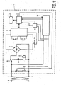
- Fig. 1 schematically shows a wire-bound telecommunication device 1 according to the present invention.
- the device 1 comprises terminals 2 and 3 for coupling to a subscriber line 4 of a telecommunication network.
- a network can be an analog public switched telephone network, or any other suitable network, preferably offering a so-called caller identification service.
- a subscriber gets information about the caller's IDentity such as the caller's telephone number and name.
- caller_ID information such information can be displayed on a display 5 comprised in the device 1.
- a so-called tone alerting signal TAS is received upon which the device 1 is prepared to receive the actual caller_ID information, e.g., in the form of FSK (Frequency Shift Keying) data (see Fig. 4 ).
- FSK Frequency Shift Keying
- the end of the tone alerting signal TAS must be detected.
- the end the TAS is signalled by two tones having the respective frequencies 2130 Hz ⁇ 1.1% and 2750 Hz ⁇ 1.1%.
- the end of TAS tones are 2130 Hz ⁇ 0.5% and 2750 Hz ⁇ 0.5%.
- the wire-bound telecommunication device 1 further comprises a transmission circuit 6 coupled to the terminals 2 and 3 via a rectifier bridge 7 and a cradle switch 8, a programmed microcontroller 9 comprising ROM and RAM memory, an energy detecting arrangement 10, and an FSK detector 11.
- the transmission circuit can be an IC type TEA106x or TEA111x, being readily available onto the market.
- the energy detecting arrangement 10 and the FSK detector 11 are coupled parallel to the subscriber line 4. Further shown is line-current interrupting transistor 12 for allowing pulse dialling. Instead of pulse dialling tone dialling can be applied. Then, via the transmission circuit 6 dialling tones are put on the subscriber line 4.
- the device 1 For processing a caller's ringing signal on the subscriber line 4, the device 1 comprises a DC-decoupled bell 13. AC-coupling is achieved by a capacitor 14. in series with the bell 13. After reception of the caller_ID information, an AC line terminating impedance 15 is switched parallel to the line 4.
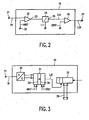
- Fig. 2 shows a first embodiment of the signal energy detector 10 according to the present invention.
- the detector 10 comprises a comparator 20 for comparing a signal IN on the subscriber line at a terminal 21 with an amplitude reference signal AREF at a terminal 22. If the signal IN exceeds the reference signal AREF, at an output 23 of the comparator 20 a signal state transition occurs, practically resulting in a sequence of non-equidistant pulses of an unequal duration. These output pulses are fed to an integrator 24 which integrates the pulses over a predetermined interval T, e.g., 8 msec. Thereafter the integrator is reset and integration starts again.
- T e.g. 8 msec
- a time-domain signal IIN is thus available representing the signal energy of a signal on the subscriber line 4 in a predetermined interval T.
- the signal IIN is compared with an energy reference signal EREF by a comparator 26.
- a control signal LLB a low-level bit, is available.
- the low-level bit can be used to detect the end of TAS tones, to detect power drops in the FSK signal, to monitor subscriber line load variations, or for any other suitable use. In the sequel use of the low level bit LLB for end of TAS detection and FSK signal power drop detection will be described in more detail.
- Fig. 3 shows a second embodiment of the signal energy detector 10 according to the present invention.
- the detector 10 comprises an analog-to-digital converter 30, a low-level bit comparator/counter 31, and s caller_ID register 32.
- the comparator/counter 31 comprises a comparator 33 functioning as an amplitude detector and a counter 34 functioning as a presetable counter.
- the amplitude detector provides pulses as described in regard of Fig. 2 and the LLB, a counter overflow bit, indicates whether the average pulse energy and herewith the average of the signal IN was above or below a given energy level.
- bit value "0" represents a relatively high energy level and a bit value "1" represents a relatively low energy level.
- detecting is not limited to a narrow predetermined frequency band, arbitrary tones can be detected and also power drops in a signal. If the signal protocol changes, e.g., because an additional pulse is included, the microcontroller 9 can easily be reprogrammed to also detect such an additional tone. Further shown in Fig. 3 is a data 35 bus for coupling of the detector 10 to the microcontroller 9.
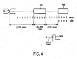
- Fig. 4 shows the signals TAS and FSK in the input signal IN on the terminals 2 and 3 of the wire-bound telecommunication device 1 according to the present invention, and the low-level bit LLB at the output 27 or in the register 32 of the detector 10. Further shown is a so-called DC-wetting pulse DCW.
- the signals TAS and FSK are included in a caller_ID signal protocol which is assumed to be known at the programming stage of the wire-bound telecommunication device 1.
- a switch (not shown) could be provided at the bottom of the device 1. At different positions of the switch imprinted indications could be given to indicate predetermined protocols. The position of such a switch could be detected by the microcontroller 9 so as to distinguish detection protocols pre-loaded in the microcontroller 9.
- the subscriber could then simply adjust the device 1 to various protocols. Because the DC-wetting pulse DCW must be available at a given time after the signal TAS, e.g., after 20 ⁇ 5 msec, the end of TAS must be detected.
- the TAS tone is applied to the line by the exchange in the network more than 110 msec after line reversal which is detected by the caller_ID IC (Integrated Circuit) switched parallel to the transmission IC 6.
- the caller_ID IC Integrated Circuit
- the energy on the subscriber line 4 is above the energy reference level EREF.
- the measurement can be done cyclically or can be triggered each time a trigger pulse is received from the microcontroller 9.
- Measurement can be started after line reversal detection or upon detection of a ringing signal.
- TAS For detecting a valid signal TAS, during a time interval having a length between 88 msec and 110 msec, the low-level bit LLB should remain "0". This time interval is fixed for a given signal protocol, e.g., the BT protocol. For this reason, energy detection can be applied for determining the presence of the signal TAS. Because the energy reference EREF is a number in a register it can easily be modified by the programmed microcontroller 9. After a valid TAS, the DC-wetting pulse DCW is generated, 20 ⁇ 5 msec after the end of TAS.
- FSK-data comprising the caller_ID information is put on the subscriber line more than 45 msec after the end of TAS.
- the DC-wetting pulse DCW is sent to the network for acknowledging the reception of a valid TAS and for preparing the device 1, notably the FSK detector 11, for the reception of data.
- data are FSK caller_ID data.
- the detector 10 can also be used for detecting power drops in the signal FSK. If such a power drop would last too long, no correct reception of caller_ID information is achieved. In such a case, the idle state impedance is restored within 150 msec. Typically, a power drop lasting more than 40 msec is interpreted as receiving invalid caller_ID data.
- Power drop is detected by the microcontroller 9 by reading the low-level bit LLB while knowing that the signal FSK is present more than 45 msec after the end of TAS. Because of this a priori known signal timing, signals can be distinguished, in the given example the signals TAS and FSK. In Fig. 4 , below the signal FSK, the low-level bit sequence "0000" indicates that there was no power drop and the low-level bit sequence "0100" indicates there actually was a power drop.
Landscapes
- Engineering & Computer Science (AREA)
- Signal Processing (AREA)
- Telephonic Communication Services (AREA)
- Telephone Function (AREA)
- Prepayment Telephone Systems (AREA)
Claims (7)
- Kabelgebundene Telekommunikationsvorrichtung (1), die Anschlüsse (2, 3) zum Verbinden der Vorrichtung mit einer Teilnehmeranschlussleitung (4) eines Telekommunikationsnetzes, eine Sendeschaltung (6) und eine Signalenergieerkennungsanordnung (10) aufweist, dadurch gekennzeichnet, dass die Signalenergieerkennungsanordnung (10) Mittel (20, 24, 26; 31) zum Ermitteln eines Zeitsignals, das die Signalenergie im vollständigen Frequenzspektrum eines Signals auf der Teilnehmerleitung in einem vorbestimmten Zeitintervall repräsentiert, zur deterministischen Signalenergieerkennung vorbestimmter Signale aufweist;
wobei die Telekommunikationsvorrichtung für Betrieb gemäß einem bestimmten Signalprotokoll ausgelegt ist, wobei die Signalenergie während wenigstens eines vorbestimmten erwarteten Signalintervalls in dem genannten vorbestimmten Zeitintervall ermittelt wird,
wobei das Signalprotokoll ein Ruferkennungssignalprotokoll ist und das Signal während des vorbestimmten erwarteten Signalintervalls ein von der Signalenergieerkennungsanordnung erkanntes Tonhinweissignal umfasst,
wobei die Signalenergieermittlung um ein weiteres erwartetes Signalintervall in dem genannten vorbestimmten Zeitintervall fortgesetzt wird, wobei das Signal ein Ruferkennungssignal während des genannten weiteren erwarteten Signalintervalls aufweist, das von einem Ruferkennungssignaldetektor erkannt wird. - Kabelgebundene Telekommunikationsvorrichtung nach Anspruch 1, wobei die Mittel (20, 24, 26; 31) zum Ermitteln eines Zeitsignals einen Komparator (20; 33) zum Vergleichen des Eingangssignals an der Teilnehmeranschlussleitung mit einem Amplitudenreferenzsignal umfassen.
- Kabelgebundene Telekommunikationsvorrichtung nach Anspruch 1, wobei die Signalenergie zyklisch ermittelt wird oder wobei die Signalenergieermittlung von einem Auslöseimpuls eingeleitet wird.
- Kabelgebundene Telekommunikationsvorrichtung nach Anspruch 1, wobei der Ruferkennungssignaldetektor dafür ausgelegt ist, von einem Einleitungsimpuls eingeleitet zu werden, der eine vorbestimmte Zeit nach Erkennung des Tonhinweissignals erzeugt wird.
- Kabelgebundene Telekommunikationsvorrichtung nach Anspruch 4, wobei der Einleitungsimpuls das Schalten einer Impedanz (15) parallel zur Teilnehmeranschlussleitung steuert.
- Kabelgebundene Telekommunikationsvorrichtung nach Anspruch 1, wobei die Signalenergieerkennungsanordnung (10) zum Überwachen von Belastungsschwankungen der Teilnehmeranschlussleitung verwendet wird.
- Erkennungsschaltung zur Verwendung in einer kabelgebundenen Telekommunikationsvorrichtung (1), die Anschlüsse (2, 3) zum Verbinden der Vorrichtung mit einer Teilnehmeranschlussleitung (4) eines Telekommunikationsnetzes und eine Sendeschaltung (6) aufweist, wobei die Erkennungsschaltung eine Signalenergieerkennungsanordnung (10) aufweist, dadurch gekennzeichnet, dass die Signalenergieerkennungsanordnung (10) Mittel (20, 24, 26; 31) zum Ermitteln eines Zeitsignals, das die Signalenergie im vollständigen Frequenzspektrum eines Signals auf der Teilnehmerleitung in einem vorbestimmten Zeitintervall repräsentiert, zur deterministischen Signalenergieerkennung vorbestimmter Signale aufweist;
wobei die Telekommunikationsvorrichtung für Betrieb gemäß einem bestimmten Signalprotokoll ausgelegt ist, wobei die Signalenergie während wenigstens eines vorbestimmten erwarteten Signalintervalls in dem vorbestimmten Zeitintervall ermittelt wird,
wobei das Signalprotokoll ein Ruferkennungssignalprotokoll ist und das Signal während des vorbestimmten erwarteten Signalintervalls ein von der Signalenergieerkennungsanordnung erkanntes Tonhinweissignal umfasst, und
wobei die Signalenergieermittlung um ein weiteres erwartetes Signalintervall in dem vorbestimmten Zeitintervall fortgesetzt wird, wobei das Signal ein Ruferkennungssignal während des genannten weiteren erwarteten Signalintervalls aufweist, das von einem Ruferkennungssignaldetektor erkannt wird.
Priority Applications (1)
| Application Number | Priority Date | Filing Date | Title |
|---|---|---|---|
| EP98945495A EP0976231B1 (de) | 1997-10-31 | 1998-10-12 | Drahtgebundenes nachrichtenübertragungsgerät und schaltkreis zur verwendung in einem solchen gerät |
Applications Claiming Priority (4)
| Application Number | Priority Date | Filing Date | Title |
|---|---|---|---|
| EP97203329 | 1997-10-31 | ||
| EP97203329 | 1997-10-31 | ||
| PCT/IB1998/001603 WO1999022562A2 (en) | 1997-10-31 | 1998-10-12 | A wire-bound telecommunication device and a circuit for use in such a device |
| EP98945495A EP0976231B1 (de) | 1997-10-31 | 1998-10-12 | Drahtgebundenes nachrichtenübertragungsgerät und schaltkreis zur verwendung in einem solchen gerät |
Publications (2)
| Publication Number | Publication Date |
|---|---|
| EP0976231A2 EP0976231A2 (de) | 2000-02-02 |
| EP0976231B1 true EP0976231B1 (de) | 2012-09-26 |
Family
ID=8228866
Family Applications (1)
| Application Number | Title | Priority Date | Filing Date |
|---|---|---|---|
| EP98945495A Expired - Lifetime EP0976231B1 (de) | 1997-10-31 | 1998-10-12 | Drahtgebundenes nachrichtenübertragungsgerät und schaltkreis zur verwendung in einem solchen gerät |
Country Status (6)
| Country | Link |
|---|---|
| US (1) | US6925170B1 (de) |
| EP (1) | EP0976231B1 (de) |
| JP (1) | JP4503104B2 (de) |
| KR (1) | KR100590776B1 (de) |
| CN (1) | CN1149817C (de) |
| WO (1) | WO1999022562A2 (de) |
Families Citing this family (1)
| Publication number | Priority date | Publication date | Assignee | Title |
|---|---|---|---|---|
| KR100547148B1 (ko) * | 2003-10-18 | 2006-01-26 | 삼성전자주식회사 | 전화망의 물리적 특성에 적응된 통신 단말 장치 및 통신단말 장치를 전화망의 물리적 특성에 적응시키기 위한 방법 |
Family Cites Families (12)
| Publication number | Priority date | Publication date | Assignee | Title |
|---|---|---|---|---|
| US4270208A (en) * | 1979-04-02 | 1981-05-26 | Harris Corporation | Threshold generator |
| US4309664A (en) * | 1979-11-13 | 1982-01-05 | Gte Laboratories Incorporated | Digital energy line sensor |
| JPH03283742A (ja) * | 1990-03-30 | 1991-12-13 | Omron Corp | 波形整形方法および装置ならびに波形整形のためのしきい値の作成方法および装置 |
| US5519774A (en) * | 1992-12-08 | 1996-05-21 | Bell Communications Research, Inc. | Method and system for detecting at a selected station an alerting signal in the presence of speech |
| US5428662A (en) * | 1993-03-01 | 1995-06-27 | Dialogic Corporation | Detecting make-break clicks on a telephone line |
| US5781588A (en) * | 1994-11-10 | 1998-07-14 | Matsushita Electric Industrial Co., Ltd. | FSK signal receiver |
| US5649002A (en) * | 1994-12-13 | 1997-07-15 | Colonial Data Technologies Corp. | Method and apparatus for detecting a telephone CPE alerting signal |
| US5550908A (en) * | 1995-06-01 | 1996-08-27 | Lucent Technologies Inc. | Modem communications interoperability with services equipped to provide calling party identity delivery with call waiting |
| US6058171A (en) * | 1996-08-14 | 2000-05-02 | Oakley Telecom, Lc | Unique ring caller ID |
| US5864607A (en) * | 1996-08-23 | 1999-01-26 | Compaq Computer Corp. | Communication with a computer using telephones |
| US5901219A (en) * | 1997-08-27 | 1999-05-04 | 3Com Corporation | Method for ring signal detection |
| US6269160B1 (en) * | 1998-04-20 | 2001-07-31 | Advanced Micro Devices, Inc. | Communications device including an improved CPE alerting signal (CAS) detection system |
-
1998
- 1998-10-12 EP EP98945495A patent/EP0976231B1/de not_active Expired - Lifetime
- 1998-10-12 JP JP52578499A patent/JP4503104B2/ja not_active Expired - Fee Related
- 1998-10-12 CN CNB988027046A patent/CN1149817C/zh not_active Expired - Lifetime
- 1998-10-12 KR KR1019997005894A patent/KR100590776B1/ko not_active Expired - Fee Related
- 1998-10-12 WO PCT/IB1998/001603 patent/WO1999022562A2/en not_active Ceased
- 1998-10-30 US US09/183,380 patent/US6925170B1/en not_active Expired - Lifetime
Also Published As
| Publication number | Publication date |
|---|---|
| WO1999022562A3 (en) | 1999-08-12 |
| KR20000069758A (ko) | 2000-11-25 |
| WO1999022562A2 (en) | 1999-05-14 |
| KR100590776B1 (ko) | 2006-06-19 |
| EP0976231A2 (de) | 2000-02-02 |
| JP2001507910A (ja) | 2001-06-12 |
| CN1248373A (zh) | 2000-03-22 |
| CN1149817C (zh) | 2004-05-12 |
| JP4503104B2 (ja) | 2010-07-14 |
| US6925170B1 (en) | 2005-08-02 |
Similar Documents
| Publication | Publication Date | Title |
|---|---|---|
| US5544241A (en) | Telephone ring detector | |
| CA2045270C (en) | Method and apparatus for processing an incoming telephone call signal which may include a data message | |
| US5859896A (en) | Telephone line automatic prefix dialer | |
| JP2000505257A (ja) | 付属電話機のオフフック状態を検出するためのモデム・ループ電流検出システム | |
| US6925170B1 (en) | Wire-bound telecommunication device and a circuit for use in such a device | |
| US5369690A (en) | Telephone call detecting circuit and a method of remotely accessing and testing a telephone | |
| US5905778A (en) | Notification apparatus for outbound data communication system | |
| AU729006B2 (en) | Method of and device for measuring echo parameters on telephone lines | |
| US5144652A (en) | Device for connecting a subscriber line to a selected internal line | |
| EP0782323A1 (de) | Verfahren und Vorrichtung zur Detektion der Anwesenheit eines periodisches Signals, das eine bekannte Periode hat | |
| KR100430513B1 (ko) | 개량된톤검출기능을구비한송신시스템,단말,톤검출기및동시에송신된복수의톤신호들을수신하는방법 | |
| KR100310242B1 (ko) | Wll 단말기에서의 전화기 다이얼 펄스 자동검출 방법 | |
| CA2113125C (en) | Apparatus and method for automatically blocking the transmission of identifying information concerning a telephone calling party | |
| JPH10224472A (ja) | 電話回線用信号レベル測定装置 | |
| JPS59160365A (ja) | 自動応答検出装置 | |
| WO1999022506A2 (en) | Telephone system with answering machine | |
| JPH05316245A (ja) | 端末用網制御装置 | |
| JPH0541732A (ja) | 電話加入者線の電圧変化検出装置及び方法 | |
| EP1107547A1 (de) | Universelles Verfahren zur Detektion der Anruferidentifizierungsinformation (CLIP) | |
| KR19980017197A (ko) | 발신측 전화번호 수신 및 출력장치 | |
| JPH09214621A (ja) | 端末網制御装置 | |
| AU2370099A (en) | Voice mail detector arrangement for a telephone | |
| JPH04306950A (ja) | 通信装置及びその制御方法 | |
| JPH0271656A (ja) | 自動発呼方式 | |
| KR200328927Y1 (ko) | 서브-하이웨이 상의 타임슬롯 데이터 모니터장치 |
Legal Events
| Date | Code | Title | Description |
|---|---|---|---|
| PUAI | Public reference made under article 153(3) epc to a published international application that has entered the european phase |
Free format text: ORIGINAL CODE: 0009012 |
|
| 17P | Request for examination filed |
Effective date: 19991115 |
|
| AK | Designated contracting states |
Kind code of ref document: A2 Designated state(s): DE ES FR GB IT |
|
| 17Q | First examination report despatched |
Effective date: 20040601 |
|
| RAP1 | Party data changed (applicant data changed or rights of an application transferred) |
Owner name: NXP B.V. |
|
| GRAP | Despatch of communication of intention to grant a patent |
Free format text: ORIGINAL CODE: EPIDOSNIGR1 |
|
| GRAS | Grant fee paid |
Free format text: ORIGINAL CODE: EPIDOSNIGR3 |
|
| RAP1 | Party data changed (applicant data changed or rights of an application transferred) |
Owner name: ST-ERICSSON SA |
|
| GRAA | (expected) grant |
Free format text: ORIGINAL CODE: 0009210 |
|
| AK | Designated contracting states |
Kind code of ref document: B1 Designated state(s): DE ES FR GB IT |
|
| REG | Reference to a national code |
Ref country code: DE Ref legal event code: R081 Ref document number: 69842857 Country of ref document: DE Owner name: OCT CIRCUIT TECHNOLOGIES INTERNATIONAL LTD., IE Free format text: FORMER OWNER: KONINKLIJKE PHILIPS ELECTRONICS N.V., EINDHOVEN, NL Ref country code: GB Ref legal event code: FG4D |
|
| REG | Reference to a national code |
Ref country code: DE Ref legal event code: R096 Ref document number: 69842857 Country of ref document: DE Effective date: 20121129 |
|
| PG25 | Lapsed in a contracting state [announced via postgrant information from national office to epo] |
Ref country code: ES Free format text: LAPSE BECAUSE OF FAILURE TO SUBMIT A TRANSLATION OF THE DESCRIPTION OR TO PAY THE FEE WITHIN THE PRESCRIBED TIME-LIMIT Effective date: 20130106 |
|
| PLBE | No opposition filed within time limit |
Free format text: ORIGINAL CODE: 0009261 |
|
| STAA | Information on the status of an ep patent application or granted ep patent |
Free format text: STATUS: NO OPPOSITION FILED WITHIN TIME LIMIT |
|
| PG25 | Lapsed in a contracting state [announced via postgrant information from national office to epo] |
Ref country code: IT Free format text: LAPSE BECAUSE OF FAILURE TO SUBMIT A TRANSLATION OF THE DESCRIPTION OR TO PAY THE FEE WITHIN THE PRESCRIBED TIME-LIMIT Effective date: 20120926 |
|
| 26N | No opposition filed |
Effective date: 20130627 |
|
| REG | Reference to a national code |
Ref country code: DE Ref legal event code: R097 Ref document number: 69842857 Country of ref document: DE Effective date: 20130627 |
|
| REG | Reference to a national code |
Ref country code: FR Ref legal event code: PLFP Year of fee payment: 19 |
|
| REG | Reference to a national code |
Ref country code: DE Ref legal event code: R082 Ref document number: 69842857 Country of ref document: DE Representative=s name: GRUENECKER PATENT- UND RECHTSANWAELTE PARTG MB, DE Ref country code: DE Ref legal event code: R081 Ref document number: 69842857 Country of ref document: DE Owner name: OCT CIRCUIT TECHNOLOGIES INTERNATIONAL LTD., IE Free format text: FORMER OWNER: ST-ERICSSON SA, PLAN-LES-OUATES, GENEVA, CH |
|
| REG | Reference to a national code |
Ref country code: FR Ref legal event code: PLFP Year of fee payment: 20 |
|
| PGFP | Annual fee paid to national office [announced via postgrant information from national office to epo] |
Ref country code: FR Payment date: 20170921 Year of fee payment: 20 Ref country code: GB Payment date: 20170925 Year of fee payment: 20 |
|
| PGFP | Annual fee paid to national office [announced via postgrant information from national office to epo] |
Ref country code: DE Payment date: 20170920 Year of fee payment: 20 |
|
| REG | Reference to a national code |
Ref country code: FR Ref legal event code: TP Owner name: OCT CIRCUIT TECHNOLOGIES INTERNATIONAL LIMITED, IE Effective date: 20180116 |
|
| REG | Reference to a national code |
Ref country code: DE Ref legal event code: R071 Ref document number: 69842857 Country of ref document: DE |
|
| REG | Reference to a national code |
Ref country code: GB Ref legal event code: PE20 Expiry date: 20181011 |
|
| PG25 | Lapsed in a contracting state [announced via postgrant information from national office to epo] |
Ref country code: GB Free format text: LAPSE BECAUSE OF EXPIRATION OF PROTECTION Effective date: 20181011 |