EP0976175B1 - Connector with secondary locking and coupling mechanism - Google Patents
Connector with secondary locking and coupling mechanism Download PDFInfo
- Publication number
- EP0976175B1 EP0976175B1 EP98910913A EP98910913A EP0976175B1 EP 0976175 B1 EP0976175 B1 EP 0976175B1 EP 98910913 A EP98910913 A EP 98910913A EP 98910913 A EP98910913 A EP 98910913A EP 0976175 B1 EP0976175 B1 EP 0976175B1
- Authority
- EP
- European Patent Office
- Prior art keywords
- secondary locking
- locking member
- connector
- housing
- coupling
- Prior art date
- Legal status (The legal status is an assumption and is not a legal conclusion. Google has not performed a legal analysis and makes no representation as to the accuracy of the status listed.)
- Expired - Lifetime
Links
Images


Classifications
-
- H—ELECTRICITY
- H01—ELECTRIC ELEMENTS
- H01R—ELECTRICALLY-CONDUCTIVE CONNECTIONS; STRUCTURAL ASSOCIATIONS OF A PLURALITY OF MUTUALLY-INSULATED ELECTRICAL CONNECTING ELEMENTS; COUPLING DEVICES; CURRENT COLLECTORS
- H01R13/00—Details of coupling devices of the kinds covered by groups H01R12/70 or H01R24/00 - H01R33/00
- H01R13/62—Means for facilitating engagement or disengagement of coupling parts or for holding them in engagement
- H01R13/629—Additional means for facilitating engagement or disengagement of coupling parts, e.g. aligning or guiding means, levers, gas pressure electrical locking indicators, manufacturing tolerances
- H01R13/62905—Additional means for facilitating engagement or disengagement of coupling parts, e.g. aligning or guiding means, levers, gas pressure electrical locking indicators, manufacturing tolerances comprising a camming member
- H01R13/62927—Comprising supplementary or additional locking means
-
- H—ELECTRICITY
- H01—ELECTRIC ELEMENTS
- H01R—ELECTRICALLY-CONDUCTIVE CONNECTIONS; STRUCTURAL ASSOCIATIONS OF A PLURALITY OF MUTUALLY-INSULATED ELECTRICAL CONNECTING ELEMENTS; COUPLING DEVICES; CURRENT COLLECTORS
- H01R13/00—Details of coupling devices of the kinds covered by groups H01R12/70 or H01R24/00 - H01R33/00
- H01R13/40—Securing contact members in or to a base or case; Insulating of contact members
- H01R13/42—Securing in a demountable manner
- H01R13/436—Securing a plurality of contact members by one locking piece or operation
- H01R13/4367—Insertion of locking piece from the rear
- H01R13/4368—Insertion of locking piece from the rear comprising a temporary and a final locking position
-
- H—ELECTRICITY
- H01—ELECTRIC ELEMENTS
- H01R—ELECTRICALLY-CONDUCTIVE CONNECTIONS; STRUCTURAL ASSOCIATIONS OF A PLURALITY OF MUTUALLY-INSULATED ELECTRICAL CONNECTING ELEMENTS; COUPLING DEVICES; CURRENT COLLECTORS
- H01R13/00—Details of coupling devices of the kinds covered by groups H01R12/70 or H01R24/00 - H01R33/00
- H01R13/62—Means for facilitating engagement or disengagement of coupling parts or for holding them in engagement
- H01R13/629—Additional means for facilitating engagement or disengagement of coupling parts, e.g. aligning or guiding means, levers, gas pressure electrical locking indicators, manufacturing tolerances
- H01R13/62905—Additional means for facilitating engagement or disengagement of coupling parts, e.g. aligning or guiding means, levers, gas pressure electrical locking indicators, manufacturing tolerances comprising a camming member
- H01R13/62911—U-shaped sliding element
Definitions
- This invention relates to an electrical connector having a secondary locking mechanism for locking terminals within cavities of the connector.
- the connector disclosed therein includes a secondary locking member which is slideable along the connector housing form a pre-assembly position to a fully locked position.
- the secondary locking element does have keying platforms and integral latches to fix it to the main housing.
- the connector disclosed therein has an insulative housing with a plurality of electrical terminals mounted therein and locked with first (primary) retention means such as resilient locking lances of the housing engaging in cavities of the terminals, the housing further provided with a secondary locking member that allows assembly of the terminals within the housing when in a preassembly position.
- the secondary locking member is movable to a locked position to secure the terminals in the housings with secondary locking means.
- the connector is further provided with a camming slide that engages with complementary members of a mating connector for coupling the connectors together.
- the coupling member reduces the forces required for mating.
- the coupling member further cooperates with the secondary locking member such that it is not movable until the secondary locking member is in the fully locked position. This ensures that connectors cannot be coupled unless the terminals are correctly mounted within their respective cavities and securely locked with primary and secondary locking means.
- a particularly reliable connection assembly is thus provided.
- a further advantage is that the camming slide cannot be moved to the wrong position during handling and transport, as it is blocked by the secondary locking member prior to complete assembly of terminals within the connector.
- connection assembly It would be desirable to reduce the maintenance and repair costs of a connection assembly, without reducing its reliability. It would also be particularly advantageous to combine such effects into a connection assembly as described in European Patent 726 617.
- an electrical connector comprising a housing and electrical terminals mounted therein, a secondary locking member mountable to the housing in a first preassembly position where the terminals can be inserted and locked into their corresponding cavities, the secondary locking member movable to a fully locked position to securely lock the terminals in their cavities with secondary locking means, the connector further comprising a coupling assist mechanism for assisting coupling with a mating connector, the coupling assist member and secondary locking member interengaging when the secondary locking member is in a preassembly position to prevent movement of the coupling assist member, wherein the secondary locking member comprises a release projection extending through a wall of the connector when the secondary locking member is in the fully locked position the release projection being manually engagable for displacing the secondary locking member from the fully locked to the preassembly position.
- the secondary locking member can be easily released to the preassembly position for cost-effective maintenance of the connector.
- the connector may advantageously comprise complementary shoulders on the secondary locking and coupling assist member that engage once the secondary locking member is in the fully locked position and the coupling assist mechanism is moved from its preassembly position, the shoulders engaging such that the secondary locking mechanism cannot be moved from the fully locked to the preassembly position once the coupling assist mechanism has been displaced out of its preassembly position.
- the latter ensures that a particularly reliable electrical connection is provided whereby the secondary locking mechanism cannot be unlocked during coupling with a complementary connector or thereafter.
- the latter also ensure that the coupling assist mechanism is moved to the preassembly position prior to unlocking of the secondary locking member.
- the secondary locking member release projections may be provided as projections extending in a direction of coupling of the connectors beyond an end wall at a terminal receiving end of the connector housing.
- the projections may be provided extending adjacent a terminal receiving portion of the housing extending beyond the terminal receiving end such that they do not extend substantially beyond an end face of the housing in order to prevent accidental release.
- an electrical connector 2 comprises an insulative housing 4 having cavities 6 for receiving electrical terminals therein, a secondary locking member 8 and a slide-lock coupling member 10.
- the housing 4 extends between a mating face 12 and a terminal receiving face 14, the housing having a terminal receiving section 17 which is surrounded by a shroud 18 and separated therefrom by a cavity section 20 within which the secondary locking member 8 and arms 22 of the slide-lock coupling member 10 are received.
- the housing terminal section 17 comprises resilient locking lances 24 integrally moulded therewith, the locking lances 24 in the shape of cantilever beams and having locking protrusions 26 proximate their free ends that project into the terminal receiving cavities 16.
- Electrical terminals can be inserted into the cavities 16 whereby passage of the terminals past the locking lance protrusions 26 causes resilient outward biasing of the locking lances until engagement of the protrusions 26 behind shoulders of the terminals to prevent removal of the terminals from their corresponding cavities 16 towards the terminal receiving end 14.
- Adjacent locking lances 24',24" of adjacent cavities 16',16" are separated by a slot 28 to allow outward biasing of the lances during mounting of the electrical terminals within their corresponding cavities.
- the secondary locking member 8 comprises a mating end wall 30 and extending therefrom a shroud 32 that fits over the mating end of the housing terminal receiving section 16. Also extending from the mating end wall 30 are short wall portions 34,36 that are positioned adjacent outer surfaces 38 of the locking lances 24 when the secondary locking housing 8 is in the fully locked position with respect to the housing 4 as shown in Figure 4. The wall portions 34,36 thus prevent outward biasing of the locking lances 24,24',24'' in order to securely lock the terminals that have been inserted into the cavity 16 and that have engaged with the locking protrusions 26 of the locking lances 24.
- the secondary locking housing 8 is shown in the preassembly position whereby the wall portions 34,36 are disengaged from the locking lances outer surfaces 38 such that the locking lances are free to bias outwardly for reception of terminals within the cavity 16.
- the secondary locking housing is held in the preassembly position by a latching means 33' shown in Figure 10 which maintains the member 8 in the preassembly position, the secondary locking member however being depressable under application of a certain force for snapping into the fully locked position as shown in Figures 4 and 8-9 where the latch means 33 securely hold the secondary locking member in this position.
- the latching means 33,33' comprises a resilient cantilever beam latch 35 integral with the secondary locking member extending from a mating end 31 of the secondary locking member to a free end 37 provided with a latch shoulder 39 that engages a corresponding preassembly latching protrusion 41' or locking latching protrusion 41 projecting from an end wall of the housing 4.
- the locking protrusion 41 is provided with an oblique locking shoulder 47 that enables disconnection of the secondary locking member from the fully locked position to the preassembly position. In other words, when the secondary locking member is pushed from the fully locked to the preassembly position the oblique locking shoulder 45 allows the latch free end 37 to resiliently outwardly bias and pass over the locking protrusion 41.
- the preassembly protrusion 41' is provided on the housing for engaging with the latch 35 of the secondary locking member in the preassembly position in a secure manner. The secondary locking member cannot be removed from the housing without special tools.
- the secondary locking member 8 further comprises locking arms 42 attached to a lower portion 40 of the shroud 32.
- the slide-lock coupling member 10 comprises a U-shaped body having a base wall 44 and side walls 46 extending laterally therefrom, the side walls 46 insertable through cutouts 48 in the connector housing shroud 18 to slide adjacent an inner surface 49 of the side walls 18 (also see Figure 5).
- the slide-lock coupling member side walls 46 comprise camming slots 50 that have a first longitudinal portion 52, extending from a complementary connector receiving end 54, the longitudinal portion 52 extending into an oblique portion 56 which then extends into a portion orthogonal to the longitudinal direction (where the longitudinal direction is the direction of coupling of the connector 2 to a complementary connector).
- the camming slots 50 are for receiving studs of a complementary connector (not shown), in order to draw the complementary connector towards the connector 2 when the slide-lock coupling member 10 is moved from the open position as shown in Figure 5 to the closed position as shown in Figure 3. The latter thus causes coupling of the connector 2 to the complementary connector.
- the slide-lock coupling member 10 Before sliding from the open to the closed position, the slide-lock coupling member 10 receives the studs of the complementary connector first into the longitudinal portion 52 of the camming slot 50, which allows initial engagement of the connector to the complementary connector.
- the studs of the complementary connector cannot enter into the camming slot lead-in portion 52 and simply abuts the complementary connector receiving end 54 of the side walls 46, thus preventing coupling of the connectors.
- the end portion 58 of the camming slots 50 is contiguous the complementary connector studs when the slide-lock coupling member 10 is in the fully closed position, and due to the orthogonal direction of the portion 58 with respect to the coupling direction of the connectors, a force tending to pull apart the connectors will not produce a force component in the orthogonal direction and thus cannot open the slide-lock member and release the connectors from the mating position.
- the slide-lock member 10 further comprises a preassembly locking shoulder 60 (see Figures 1 and 3) on the inner surface of the side walls 46, against which latching protrusions 43 at ends 45 of the secondary locking member locking arms 42 engage, when in the preassembly position as shown in Figure 3.
- a preassembly locking shoulder 60 see Figures 1 and 3
- the secondary locking member 8 is in the preassembly position and the slide-lock member 10 is in the fully closed position as shown in Figure 3, whereby the spring arm protrusions 43 engage with the shoulder 60.
- the slide-lock member 10 can thus not be moved into the open position and can therefore not be coupled to a complementary connector.
- Adjacent the shoulder 60 Adjacent the shoulder 60 extends a recess 62 having a closed position notch 64 extending proximate the shoulder 60 and a preassembly position notch 66 proximate ends of the side walls 46 distant from the end wall 44.
- Proximate the open position notch 66 is a retention shoulder 68 for engagement with the latching protrusions 43 to prevent removal of the slide-lock member 10 from the housing 4 as shown in Figure 5.
- the secondary locking member 8 is moved from the preassembly position shown in Figure 2 to its fully locked position shown in Figure 4, the latching protrusion 43 disengages from the shoulder 60 and moves into the recessed area 62 to engage in the closed position notch 64.
- the notch 64 engages with the latching protrusion 43 to provide a certain resistance to moving the slide-lock member 10, but if sufficient force is applied to the slide-lock member, it can be drawn to the open position as shown in Figure 5 where the latch protrusion 43 engages in the open position notches 66 for provisionally holding the slide-lock member in the open position.
- the connector 2 can thus be coupled to the complementary connector and the slide-lock member 10 is then depressed to the fully closed position, thereby drawing the connectors together and coupling them. In the closed position, the slide-lock member 10 is latched with a certain force by engagement of the notches 64 with the spring beam latch protrusions 43.
- the secondary locking member 8 cannot be moved to the preassembly position. The latter occurs by virtue of engagement of the latching protrusion 43 with an upper shoulder 70 as best seen in Figures 1 and 4, of the slide lock member 10. Therefore, once coupling of the connectors is permitted by movement of the secondary locking member to the locked position, and the slide lock member 10 is displaced for example during coupling of mating connectors, it is no longer possible to accidentally displace the secondary locking member out of its fully locked position.
- the secondary locking member 8 further comprises actuators 72 extending from side walls thereof alongside a terminal receiving portion 74 of the housing 4.
- the actuators 72 project through cavities 76 of a terminal receiving end wall 78 opposed to the mating end 12 of the connector.
- the terminal receiving end wall 78 is spaced at a certain distance from the outermost terminal receiving end 14 of the housing, which defines the end of the terminal receiving portion 74 of the housing.
- the actuators 72 extend to a position proximate the terminal receiving end 14 of the housing portion 74 such that they can be manually activated (for example by hand) in order to displace the secondary locking member back to its preassembly position as shown in Figure 2.
- the extensions 72 may be positioned substantially at the end walls 78 or in the proximity thereof.
- the secondary locking member 8 cannot be activated until the slide lock member 10 is in its preassembly position, which may be the open or closed position depending on the chosen embodiment.
- the secondary locking member latching features 35,37 that cooperate with the locking protrusion 41 provides a certain resistance, in view of the oblique latching surface 47 to displacement of the secondary locking member to the preassembly position.
- the protrusion 41' has a locking surface that is angled slightly to encourage the latch arm 45 to bias into a tighter locking relationship with the housing. In other words, the latch can be pushed from the fully locked to the preassembly position but not released from the connector housing unless special tooling is used.
- the actuator 72 extends alongside and is proximate or may even be in a contiguous relationship with side walls 75 of the terminal receiving portion 74, they are protected from damage and inadvertent actuation thereof even when in the fully locked position as shown in Figure 4. A person can however easily access the actuator 72 with their fingers.
- the actuator 72 also provides a clear visual indication of the secondary locking member being in its fully locked position.
Landscapes
- Details Of Connecting Devices For Male And Female Coupling (AREA)
- Connector Housings Or Holding Contact Members (AREA)
Abstract
Description
- This invention relates to an electrical connector having a secondary locking mechanism for locking terminals within cavities of the connector.
- Such a connector is described in United States Patent 4,944,688. The connector disclosed therein includes a secondary locking member which is slideable along the connector housing form a pre-assembly position to a fully locked position. The secondary locking element does have keying platforms and integral latches to fix it to the main housing.
- An electrical connector having a secondary locking mechanism and further comprising a coupling member for assisting coupling of the connector to a complementary connector is described in European Patent 726 617. The connector disclosed therein has an insulative housing with a plurality of electrical terminals mounted therein and locked with first (primary) retention means such as resilient locking lances of the housing engaging in cavities of the terminals, the housing further provided with a secondary locking member that allows assembly of the terminals within the housing when in a preassembly position. The secondary locking member is movable to a locked position to secure the terminals in the housings with secondary locking means. The connector is further provided with a camming slide that engages with complementary members of a mating connector for coupling the connectors together. The coupling member reduces the forces required for mating. The coupling member further cooperates with the secondary locking member such that it is not movable until the secondary locking member is in the fully locked position. This ensures that connectors cannot be coupled unless the terminals are correctly mounted within their respective cavities and securely locked with primary and secondary locking means. A particularly reliable connection assembly is thus provided. A further advantage is that the camming slide cannot be moved to the wrong position during handling and transport, as it is blocked by the secondary locking member prior to complete assembly of terminals within the connector.
- One of the problems of the above described connector system, which is also a problem of many other connectors with secondary locking members with or without camming slides, is that once the secondary locking member has been pushed to the fully locked position it is difficult to disengage. In particular, it is typical that special tooling is required to move the secondary locking member from the fully locked to the preassembly position. Once the secondary locking member is in the fully locked position it is desirable that it cannot be easily disengaged as this may reduce the reliability of the connection assembly if this could occur accidentally. The use of a special tool however may lead to damage of the connector if it is not correctly utilized by a technician, and furthermore increases the costs of repair or maintenance of the connection system.
- It would be desirable to reduce the maintenance and repair costs of a connection assembly, without reducing its reliability. It would also be particularly advantageous to combine such effects into a connection assembly as described in European Patent 726 617.
- It is an object of this invention to provide an improved electrical connector with secondary locking means. It would be particularly advantageous to provide such connector with a coupling assist mechanism cooperating with the secondary locking mechanism such as described in EP 726 617.
- Objects of this invention have been achieved by providing the connector assembly according to claim 1. Disclosed is an electrical connector comprising a housing and electrical terminals mounted therein, a secondary locking member mountable to the housing in a first preassembly position where the terminals can be inserted and locked into their corresponding cavities, the secondary locking member movable to a fully locked position to securely lock the terminals in their cavities with secondary locking means, the connector further comprising a coupling assist mechanism for assisting coupling with a mating connector, the coupling assist member and secondary locking member interengaging when the secondary locking member is in a preassembly position to prevent movement of the coupling assist member, wherein the secondary locking member comprises a release projection extending through a wall of the connector when the secondary locking member is in the fully locked position the release projection being manually engagable for displacing the secondary locking member from the fully locked to the preassembly position. Advantageously therefore, the secondary locking member can be easily released to the preassembly position for cost-effective maintenance of the connector.
- The connector may advantageously comprise complementary shoulders on the secondary locking and coupling assist member that engage once the secondary locking member is in the fully locked position and the coupling assist mechanism is moved from its preassembly position, the shoulders engaging such that the secondary locking mechanism cannot be moved from the fully locked to the preassembly position once the coupling assist mechanism has been displaced out of its preassembly position. The latter ensures that a particularly reliable electrical connection is provided whereby the secondary locking mechanism cannot be unlocked during coupling with a complementary connector or thereafter. The latter also ensure that the coupling assist mechanism is moved to the preassembly position prior to unlocking of the secondary locking member.
- The secondary locking member release projections may be provided as projections extending in a direction of coupling of the connectors beyond an end wall at a terminal receiving end of the connector housing. The projections may be provided extending adjacent a terminal receiving portion of the housing extending beyond the terminal receiving end such that they do not extend substantially beyond an end face of the housing in order to prevent accidental release.
- Further advantageous aspects of this invention are described in the claims or will be apparent from the following description and drawings.
- An embodiment of this invention will now be described by way of example with reference to the drawings in which;
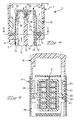
- Figure 1 is an isometric view of an embodiment of this invention with secondary locking and slide-lock coupling members exploded away;
- Figure 2 is a cross-sectional view through the connector with the slide-lock coupling member in a fully locked position and the secondary locking member in a preassembled position;
- Figure 3 is a cross-sectional view through lines 3-3 of Figure 2;
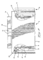
- Figure 4 is a similar view to that of Figure 2, but with the slide-lock member in a fully open position and the secondary locking member in a fully locked position;
- Figure 5 is a cross-sectional view through lines 5-5 of Figure 4;
- Figure 6 is an isometric view of an embodiment of this invention with secondary locking and slide lock coupling members viewing in a direction towards a terminal receiving end, where the secondary locking member is in the preassembly position;
- Figure 7 is a view similar to Figure 6 with the secondary locking member in the fully locked position;
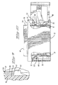
- Figure 8 is a side view of the embodiment of Figures 6 and 7, with partial cross-sections, where the secondary locking member is in the fully locked position;
- Figure 9 is a detailed view of the latching means between the secondary locking member and the housing;
- Figure 10 is a view similar to Figure 8 with the secondary locking member in the preassembly position.
-
- Referring to Figure 1, an
electrical connector 2 comprises aninsulative housing 4 having cavities 6 for receiving electrical terminals therein, asecondary locking member 8 and a slide-lock coupling member 10. - Referring to Figures 1-3, the
housing 4 extends between amating face 12 and a terminal receivingface 14, the housing having aterminal receiving section 17 which is surrounded by ashroud 18 and separated therefrom by acavity section 20 within which thesecondary locking member 8 andarms 22 of the slide-lock coupling member 10 are received. Thehousing terminal section 17 comprisesresilient locking lances 24 integrally moulded therewith, thelocking lances 24 in the shape of cantilever beams and having lockingprotrusions 26 proximate their free ends that project into theterminal receiving cavities 16. Electrical terminals can be inserted into thecavities 16 whereby passage of the terminals past thelocking lance protrusions 26 causes resilient outward biasing of the locking lances until engagement of theprotrusions 26 behind shoulders of the terminals to prevent removal of the terminals from theircorresponding cavities 16 towards theterminal receiving end 14.Adjacent locking lances 24',24" ofadjacent cavities 16',16" are separated by aslot 28 to allow outward biasing of the lances during mounting of the electrical terminals within their corresponding cavities. - The
secondary locking member 8 comprises amating end wall 30 and extending therefrom ashroud 32 that fits over the mating end of the housingterminal receiving section 16. Also extending from themating end wall 30 areshort wall portions outer surfaces 38 of thelocking lances 24 when thesecondary locking housing 8 is in the fully locked position with respect to thehousing 4 as shown in Figure 4. Thewall portions locking lances 24,24',24'' in order to securely lock the terminals that have been inserted into thecavity 16 and that have engaged with thelocking protrusions 26 of thelocking lances 24. In Figures 2 and 10, thesecondary locking housing 8 is shown in the preassembly position whereby thewall portions outer surfaces 38 such that the locking lances are free to bias outwardly for reception of terminals within thecavity 16. The secondary locking housing is held in the preassembly position by a latching means 33' shown in Figure 10 which maintains themember 8 in the preassembly position, the secondary locking member however being depressable under application of a certain force for snapping into the fully locked position as shown in Figures 4 and 8-9 where the latch means 33 securely hold the secondary locking member in this position. The latching means 33,33' comprises a resilientcantilever beam latch 35 integral with the secondary locking member extending from amating end 31 of the secondary locking member to afree end 37 provided with alatch shoulder 39 that engages a corresponding preassembly latching protrusion 41' or lockinglatching protrusion 41 projecting from an end wall of thehousing 4. Thelocking protrusion 41 is provided with anoblique locking shoulder 47 that enables disconnection of the secondary locking member from the fully locked position to the preassembly position. In other words, when the secondary locking member is pushed from the fully locked to the preassembly position theoblique locking shoulder 45 allows the latchfree end 37 to resiliently outwardly bias and pass over thelocking protrusion 41. The preassembly protrusion 41' is provided on the housing for engaging with thelatch 35 of the secondary locking member in the preassembly position in a secure manner. The secondary locking member cannot be removed from the housing without special tools. - The
secondary locking member 8 further comprises lockingarms 42 attached to alower portion 40 of theshroud 32. - Referring to Figure 1, the slide-
lock coupling member 10 comprises a U-shaped body having abase wall 44 andside walls 46 extending laterally therefrom, theside walls 46 insertable throughcutouts 48 in theconnector housing shroud 18 to slide adjacent aninner surface 49 of the side walls 18 (also see Figure 5). The slide-lock couplingmember side walls 46 comprisecamming slots 50 that have a firstlongitudinal portion 52, extending from a complementaryconnector receiving end 54, thelongitudinal portion 52 extending into anoblique portion 56 which then extends into a portion orthogonal to the longitudinal direction (where the longitudinal direction is the direction of coupling of theconnector 2 to a complementary connector). Thecamming slots 50 are for receiving studs of a complementary connector (not shown), in order to draw the complementary connector towards theconnector 2 when the slide-lock coupling member 10 is moved from the open position as shown in Figure 5 to the closed position as shown in Figure 3. The latter thus causes coupling of theconnector 2 to the complementary connector. Before sliding from the open to the closed position, the slide-lock coupling member 10 receives the studs of the complementary connector first into thelongitudinal portion 52 of thecamming slot 50, which allows initial engagement of the connector to the complementary connector. If the slide-lock coupling member 10 is in the closed position prior to coupling to the complementary connector, the studs of the complementary connector cannot enter into the camming slot lead-inportion 52 and simply abuts the complementaryconnector receiving end 54 of theside walls 46, thus preventing coupling of the connectors. Theend portion 58 of thecamming slots 50 is contiguous the complementary connector studs when the slide-lock coupling member 10 is in the fully closed position, and due to the orthogonal direction of theportion 58 with respect to the coupling direction of the connectors, a force tending to pull apart the connectors will not produce a force component in the orthogonal direction and thus cannot open the slide-lock member and release the connectors from the mating position. - The slide-
lock member 10 further comprises a preassembly locking shoulder 60 (see Figures 1 and 3) on the inner surface of theside walls 46, against which latchingprotrusions 43 atends 45 of the secondary lockingmember locking arms 42 engage, when in the preassembly position as shown in Figure 3. During assembly of the terminals into thehousing cavities 16, thesecondary locking member 8 is in the preassembly position and the slide-lock member 10 is in the fully closed position as shown in Figure 3, whereby thespring arm protrusions 43 engage with theshoulder 60. The slide-lock member 10 can thus not be moved into the open position and can therefore not be coupled to a complementary connector. - It would also be possible to have an embodiment where the slide-lock member is locked in the open position by engagement with the secondary locking member to prevent coupling, rather than locked in the closed position as shown in the embodiment of Figures 1-5.
- Adjacent the
shoulder 60 extends arecess 62 having aclosed position notch 64 extending proximate theshoulder 60 and a preassembly position notch 66 proximate ends of theside walls 46 distant from theend wall 44. Proximate theopen position notch 66 is aretention shoulder 68 for engagement with the latchingprotrusions 43 to prevent removal of the slide-lock member 10 from thehousing 4 as shown in Figure 5. When thesecondary locking member 8 is moved from the preassembly position shown in Figure 2 to its fully locked position shown in Figure 4, the latchingprotrusion 43 disengages from theshoulder 60 and moves into the recessedarea 62 to engage in theclosed position notch 64. Thenotch 64 engages with the latchingprotrusion 43 to provide a certain resistance to moving the slide-lock member 10, but if sufficient force is applied to the slide-lock member, it can be drawn to the open position as shown in Figure 5 where thelatch protrusion 43 engages in theopen position notches 66 for provisionally holding the slide-lock member in the open position. Theconnector 2 can thus be coupled to the complementary connector and the slide-lock member 10 is then depressed to the fully closed position, thereby drawing the connectors together and coupling them. In the closed position, the slide-lock member 10 is latched with a certain force by engagement of thenotches 64 with the springbeam latch protrusions 43. - Once the slide lock member has been moved from its preassembly position where it is locked by the latch protrusion 43 (where the slide lock member may either be in the open or closed position depending on the choice of the embodiment as described above), the
secondary locking member 8 cannot be moved to the preassembly position. The latter occurs by virtue of engagement of the latchingprotrusion 43 with anupper shoulder 70 as best seen in Figures 1 and 4, of theslide lock member 10. Therefore, once coupling of the connectors is permitted by movement of the secondary locking member to the locked position, and theslide lock member 10 is displaced for example during coupling of mating connectors, it is no longer possible to accidentally displace the secondary locking member out of its fully locked position. - The
secondary locking member 8 further comprisesactuators 72 extending from side walls thereof alongside aterminal receiving portion 74 of thehousing 4. Theactuators 72 project throughcavities 76 of a terminal receivingend wall 78 opposed to themating end 12 of the connector. The terminal receivingend wall 78 is spaced at a certain distance from the outermostterminal receiving end 14 of the housing, which defines the end of theterminal receiving portion 74 of the housing. When the secondary locking member is in the fully locked position as shown in Figure 4, theactuators 72 extend to a position proximate theterminal receiving end 14 of thehousing portion 74 such that they can be manually activated (for example by hand) in order to displace the secondary locking member back to its preassembly position as shown in Figure 2. In the latter position, theextensions 72 may be positioned substantially at theend walls 78 or in the proximity thereof. - As mentioned previously, the
secondary locking member 8 cannot be activated until theslide lock member 10 is in its preassembly position, which may be the open or closed position depending on the chosen embodiment. Referring mainly to Figures 8-10, the secondary locking member latching features 35,37 that cooperate with the lockingprotrusion 41 provides a certain resistance, in view of theoblique latching surface 47 to displacement of the secondary locking member to the preassembly position. The protrusion 41' has a locking surface that is angled slightly to encourage thelatch arm 45 to bias into a tighter locking relationship with the housing. In other words, the latch can be pushed from the fully locked to the preassembly position but not released from the connector housing unless special tooling is used. - As the
actuator 72 extends alongside and is proximate or may even be in a contiguous relationship withside walls 75 of theterminal receiving portion 74, they are protected from damage and inadvertent actuation thereof even when in the fully locked position as shown in Figure 4. A person can however easily access theactuator 72 with their fingers. Theactuator 72 also provides a clear visual indication of the secondary locking member being in its fully locked position.
Claims (9)
- An electrical connector comprising a housing (4) and electrical terminals mounted therein, and a secondary locking member (8) mountable to the housing in a first preassembly position where the terminals can be inserted and locked into their corresponding cavities, the secondary locking member movable to a fully locked position to securely lock the terminals in their cavities with secondary locking means (34,36), the housing extending from a mating end (12) facing a complementary connector to be mated with the connector, to a terminal receiving end (14) where terminals are received in cavities (16) of the housing, the housing comprising an end wall (78) at or proximate the terminal receiving end (14), the secondary locking member (8) being mountable in the housing from the mating end (12), wherein the secondary locking member comprises at least one actuator (72) projecting through a cavity (76) in the end wall (78) when the secondary locking member is in the fully locked position, such that the actuator can be manually activated to move the secondary locking member from the fully locked to the preassembly position.
- The connectcr of claim 1 wherein a terminal receiving portion (74) of the housing, within which the terminal receiving cavities (16) are provided, extends beyond the end wall (78) to the terminal receiving end (14), the actuator (72) extending proximate and alongside the terminal receiving portion (74).
- The connector of claim 2 wherein the actuator (72) extends beyond the end wall (78) when the secondary locking member is in the fully locked position, substantially to or before the terminal receiving end (14).
- The connector of any one of the preceding claims wherein the secondary locking member actuator (72) is arranged substantially fully within the connector housing when the secondary locking member is in the preassembly position.
- The connector of any one of the preceding claims wherein the secondary locking member and connector housing (4) are provided with cooperating latching means (33,33'), a first latching means (33') thereof securing the secondary locking member to the housing in the preassembly position such that the secondary locking member cannot be removed manually from the housing, and a second latching means (33) thereof comprising a latching protrusion (41) having an oblique latching surface (47) engagable with a complementary resilient latching member (35) when the secondary locking member is in a fully locked position such that upon application of a releasing force on the actuator (72) the resilient latches are biased over the latching protrusion (41).
- The electrical connector of any one of the preceding claims wherein the connector further has a coupling assist member (10) for assisting coupling with a mating connector, the coupling assist member and secondary locking member interengaging when the secondary locking member is in a preassembly position to prevent movement of the coupling assist member.
- The connector of claim 6 wherein the coupling assist member comprises a locking shoulder (70) which engages with a complementary locking arm (42) of the secondary locking member (8) when the secondary locking member is in the fully locked position and the coupling assist member is displaced from its preassembly position, such that the secondary locking member is prevented from displacement to the preassembly position.
- The connector of claim 7 wherein the secondary locking member locking arm (42) engages a complementary shoulder (60) of the slide lock member when the secondary locking member is in the preassembly position and the slide lock member is in the preassembly position in order to prevent movement of the coupling assist member.
- The connector of claim 6 wherein the coupling assist member comprises a U-shaped body having a base wall (44) and side walls (46) extending laterally therefrom, the side walls insertable through cutouts (48) in a connector housing shroud (18) to slide adjacent an inner surface (49) thereof, the coupling member side walls (46) comprising camming slots (50) for receiving complementary studs of the mating connector.
Priority Applications (1)
| Application Number | Priority Date | Filing Date | Title |
|---|---|---|---|
| EP98910913A EP0976175B1 (en) | 1997-04-15 | 1998-04-09 | Connector with secondary locking and coupling mechanism |
Applications Claiming Priority (4)
| Application Number | Priority Date | Filing Date | Title |
|---|---|---|---|
| EP97400855 | 1997-04-15 | ||
| EP97400855 | 1997-04-15 | ||
| EP98910913A EP0976175B1 (en) | 1997-04-15 | 1998-04-09 | Connector with secondary locking and coupling mechanism |
| PCT/IB1998/000524 WO1998047204A1 (en) | 1997-04-15 | 1998-04-09 | Connector with secondary locking and coupling mechanism |
Publications (2)
| Publication Number | Publication Date |
|---|---|
| EP0976175A1 EP0976175A1 (en) | 2000-02-02 |
| EP0976175B1 true EP0976175B1 (en) | 2002-06-26 |
Family
ID=8229740
Family Applications (1)
| Application Number | Title | Priority Date | Filing Date |
|---|---|---|---|
| EP98910913A Expired - Lifetime EP0976175B1 (en) | 1997-04-15 | 1998-04-09 | Connector with secondary locking and coupling mechanism |
Country Status (6)
| Country | Link |
|---|---|
| US (1) | US6149473A (en) |
| EP (1) | EP0976175B1 (en) |
| JP (1) | JP2001525106A (en) |
| AU (1) | AU6513798A (en) |
| DE (1) | DE69806239T2 (en) |
| WO (1) | WO1998047204A1 (en) |
Families Citing this family (17)
| Publication number | Priority date | Publication date | Assignee | Title |
|---|---|---|---|---|
| DE19900514C1 (en) * | 1999-01-08 | 2000-08-17 | Framatome Connectors Int | Connector arrangement with control surface slide |
| DE19933929A1 (en) * | 1999-07-20 | 2001-01-25 | Delphi Tech Inc | Carrier system |
| EP1100160B1 (en) * | 1999-11-10 | 2007-03-21 | Molex Incorporated | Electrical connector assembly with improved camming system |
| EP1263090B1 (en) * | 2001-06-01 | 2011-07-06 | Tyco Electronics France SAS | Electrical connector with a coupling member in the shape of a rotatable lever arm |
| EP1306931A1 (en) * | 2001-10-29 | 2003-05-02 | Tyco Electronics France SAS | Electrical connector assembly |
| DE10252843A1 (en) * | 2002-11-13 | 2004-06-03 | Delphi Technologies, Inc., Troy | Electrical connector |
| FR2849541B1 (en) * | 2002-12-27 | 2006-08-11 | Renault Sa | ELECTRICAL CONNECTION DEVICE. |
| KR100932460B1 (en) * | 2005-04-27 | 2009-12-17 | 후지쯔 가부시끼가이샤 | Function Expansion Units and Electronic Systems for Electronics |
| EP1739795B1 (en) * | 2005-06-30 | 2007-12-26 | Sumitomo Wiring Systems, Ltd. | A connector, a connector assembly and assembling method therefor |
| JP3987078B2 (en) * | 2005-08-31 | 2007-10-03 | 日本電信電話株式会社 | Optical connector |
| US7416426B2 (en) * | 2006-01-31 | 2008-08-26 | Fci Americas Technology, Inc. | Push mate assisted electrical connector |
| US7347704B2 (en) * | 2006-03-01 | 2008-03-25 | Sumitomo Wiring Systems, Ltd. | Connector |
| US7559779B1 (en) | 2008-05-14 | 2009-07-14 | Cinch Connectors, Inc. | Electrical connector |
| WO2013135849A1 (en) * | 2012-03-16 | 2013-09-19 | Delphi Connection Systems Holding France | Electrical connector |
| US20150173231A1 (en) * | 2013-12-13 | 2015-06-18 | Sanmina Corporation | Tray assembly for a rack mount type storage unit |
| JP6607088B2 (en) * | 2016-03-04 | 2019-11-20 | 住友電装株式会社 | connector |
| WO2018061981A1 (en) * | 2016-09-29 | 2018-04-05 | タイコエレクトロニクスジャパン合同会社 | Connector assembly |
Family Cites Families (7)
| Publication number | Priority date | Publication date | Assignee | Title |
|---|---|---|---|---|
| US4944688A (en) * | 1989-09-25 | 1990-07-31 | Amp Incorporated | Programmable sealed connector |
| DE69326696T2 (en) * | 1993-11-26 | 2000-06-08 | Molex Inc., Lisle | Electrical connector with cover and end position safety device |
| FR2730587B3 (en) * | 1995-02-09 | 1997-04-30 | Amp France | ELECTRICAL CONNECTOR WITH SECONDARY LOCKING AND COUPLING MECHANISMS |
| JP3296707B2 (en) * | 1995-12-22 | 2002-07-02 | 古河電気工業株式会社 | Connector with terminal stopper |
| DE19704356C2 (en) * | 1996-02-05 | 1999-11-25 | Yazaki Corp | Connector with a part for detecting the engagement of connectors |
| JP3322803B2 (en) * | 1996-09-09 | 2002-09-09 | 矢崎総業株式会社 | Spacer locking structure |
| JP3312644B2 (en) * | 1997-03-05 | 2002-08-12 | 矢崎総業株式会社 | LIF connector |
-
1998
- 1998-04-09 US US09/402,960 patent/US6149473A/en not_active Expired - Fee Related
- 1998-04-09 EP EP98910913A patent/EP0976175B1/en not_active Expired - Lifetime
- 1998-04-09 DE DE69806239T patent/DE69806239T2/en not_active Expired - Lifetime
- 1998-04-09 JP JP54366198A patent/JP2001525106A/en active Pending
- 1998-04-09 WO PCT/IB1998/000524 patent/WO1998047204A1/en active IP Right Grant
- 1998-04-09 AU AU65137/98A patent/AU6513798A/en not_active Abandoned
Also Published As
| Publication number | Publication date |
|---|---|
| JP2001525106A (en) | 2001-12-04 |
| EP0976175A1 (en) | 2000-02-02 |
| US6149473A (en) | 2000-11-21 |
| DE69806239T2 (en) | 2003-02-06 |
| DE69806239D1 (en) | 2002-08-01 |
| AU6513798A (en) | 1998-11-11 |
| WO1998047204A1 (en) | 1998-10-22 |
Similar Documents
| Publication | Publication Date | Title |
|---|---|---|
| EP0726617B1 (en) | Connector with secondary locking and coupling mechanism | |
| EP0976175B1 (en) | Connector with secondary locking and coupling mechanism | |
| EP0984522B1 (en) | Electrical connector position assurance system | |
| US5910027A (en) | Connector position assurance | |
| EP2218149B1 (en) | Electrical connector assembly having connector position assurance device | |
| US5833484A (en) | Connector with pivotable coupling lever | |
| JP4405164B2 (en) | Electrical connector assembly and electrical connector half assembly | |
| EP0791987A2 (en) | Electrical connector with push button locking mechanism | |
| EP1221743B1 (en) | Electrical connector assembly | |
| EP1054481B1 (en) | A connector | |
| US5797772A (en) | Connector provided with a retainer | |
| EP0952634A2 (en) | Electrical connector position assurance system | |
| CN112152018A (en) | Connector set with locking device | |
| CN110571567B (en) | Staged release electrical connector assembly | |
| EP3769377B1 (en) | Connector position assurance member | |
| EP0801441A1 (en) | Low insertion pressure connector | |
| US6142826A (en) | Sealed electrical connector with secondary locking member | |
| EP1891712B1 (en) | Electrical connector with security locking system | |
| US7578709B2 (en) | Contact locking device for an electric connector and electric connector containing said device | |
| US5928014A (en) | Electrical connector having a pair of connector housings | |
| US20230123938A1 (en) | Connector assembly for connecting signal conductors | |
| EP0803936B1 (en) | Connector with terminal position assurance member | |
| EP1006380B1 (en) | Electrical and/or optical connector | |
| GB2310087A (en) | Push button latching and locking mechanism | |
| US6220886B1 (en) | Connector |
Legal Events
| Date | Code | Title | Description |
|---|---|---|---|
| PUAI | Public reference made under article 153(3) epc to a published international application that has entered the european phase |
Free format text: ORIGINAL CODE: 0009012 |
|
| 17P | Request for examination filed |
Effective date: 19991004 |
|
| AK | Designated contracting states |
Kind code of ref document: A1 Designated state(s): DE FR GB |
|
| GRAG | Despatch of communication of intention to grant |
Free format text: ORIGINAL CODE: EPIDOS AGRA |
|
| 17Q | First examination report despatched |
Effective date: 20010531 |
|
| GRAG | Despatch of communication of intention to grant |
Free format text: ORIGINAL CODE: EPIDOS AGRA |
|
| GRAH | Despatch of communication of intention to grant a patent |
Free format text: ORIGINAL CODE: EPIDOS IGRA |
|
| GRAA | (expected) grant |
Free format text: ORIGINAL CODE: 0009210 |
|
| AK | Designated contracting states |
Kind code of ref document: B1 Designated state(s): DE FR GB |
|
| REG | Reference to a national code |
Ref country code: GB Ref legal event code: FG4D |
|
| REF | Corresponds to: |
Ref document number: 69806239 Country of ref document: DE Date of ref document: 20020801 |
|
| ET | Fr: translation filed | ||
| PLBE | No opposition filed within time limit |
Free format text: ORIGINAL CODE: 0009261 |
|
| STAA | Information on the status of an ep patent application or granted ep patent |
Free format text: STATUS: NO OPPOSITION FILED WITHIN TIME LIMIT |
|
| 26N | No opposition filed |
Effective date: 20030327 |
|
| REG | Reference to a national code |
Ref country code: FR Ref legal event code: PLFP Year of fee payment: 19 |
|
| REG | Reference to a national code |
Ref country code: FR Ref legal event code: PLFP Year of fee payment: 20 |
|
| PGFP | Annual fee paid to national office [announced via postgrant information from national office to epo] |
Ref country code: GB Payment date: 20170427 Year of fee payment: 20 Ref country code: DE Payment date: 20170427 Year of fee payment: 20 Ref country code: FR Payment date: 20170426 Year of fee payment: 20 |
|
| REG | Reference to a national code |
Ref country code: DE Ref legal event code: R071 Ref document number: 69806239 Country of ref document: DE |
|
| REG | Reference to a national code |
Ref country code: GB Ref legal event code: PE20 Expiry date: 20180408 |
|
| PG25 | Lapsed in a contracting state [announced via postgrant information from national office to epo] |
Ref country code: GB Free format text: LAPSE BECAUSE OF EXPIRATION OF PROTECTION Effective date: 20180408 |