EP0803936B1 - Connector with terminal position assurance member - Google Patents
Connector with terminal position assurance member Download PDFInfo
- Publication number
- EP0803936B1 EP0803936B1 EP97106358A EP97106358A EP0803936B1 EP 0803936 B1 EP0803936 B1 EP 0803936B1 EP 97106358 A EP97106358 A EP 97106358A EP 97106358 A EP97106358 A EP 97106358A EP 0803936 B1 EP0803936 B1 EP 0803936B1
- Authority
- EP
- European Patent Office
- Prior art keywords
- connector
- housing
- assurance member
- terminal
- position assurance
- Prior art date
- Legal status (The legal status is an assumption and is not a legal conclusion. Google has not performed a legal analysis and makes no representation as to the accuracy of the status listed.)
- Expired - Lifetime
Links
- 230000013011 mating Effects 0.000 claims description 22
- 230000037431 insertion Effects 0.000 description 4
- 238000003780 insertion Methods 0.000 description 4
- 238000000926 separation method Methods 0.000 description 4
- 230000000295 complement effect Effects 0.000 description 3
- 238000006073 displacement reaction Methods 0.000 description 3
- 230000000994 depressogenic effect Effects 0.000 description 2
- 230000014759 maintenance of location Effects 0.000 description 2
- 230000000903 blocking effect Effects 0.000 description 1
- 239000003086 colorant Substances 0.000 description 1
- 239000004020 conductor Substances 0.000 description 1
- 230000000717 retained effect Effects 0.000 description 1
- 239000007787 solid Substances 0.000 description 1
- 230000000007 visual effect Effects 0.000 description 1
Images


Classifications
-
- H—ELECTRICITY
- H01—ELECTRIC ELEMENTS
- H01R—ELECTRICALLY-CONDUCTIVE CONNECTIONS; STRUCTURAL ASSOCIATIONS OF A PLURALITY OF MUTUALLY-INSULATED ELECTRICAL CONNECTING ELEMENTS; COUPLING DEVICES; CURRENT COLLECTORS
- H01R13/00—Details of coupling devices of the kinds covered by groups H01R12/70 or H01R24/00 - H01R33/00
- H01R13/40—Securing contact members in or to a base or case; Insulating of contact members
- H01R13/42—Securing in a demountable manner
- H01R13/436—Securing a plurality of contact members by one locking piece or operation
- H01R13/4361—Insertion of locking piece perpendicular to direction of contact insertion
- H01R13/4362—Insertion of locking piece perpendicular to direction of contact insertion comprising a temporary and a final locking position
Definitions
- This invention relates to an electrical connector having a terminal position assurance member for ensuring that electrical terminals are securely held in the housing.
- Certain electrical connectors are provided with housings having cavities extending therethrough for receiving terminals, each cavity provided with a resilient locking lance integrally molded with the housing for locking a terminal inserted therein.
- a secondary housing member that is moveable against the locking lances to prevent the locking lances from outwardly biasing. In other words, the locking lances are blocked into their latching position. It is known to provide the secondary member pre-assembled to the housing in a pre-assembly position that allows insertion of the terminals into the connector cavities. The secondary member can then be moved to a fully locked position whereby the terminals are locked in the cavities.
- the secondary member is protected by a shroud that extends beyond a mating face of the connector, to prevent the secondary locking member from accidentally being pushed from the pre-assembly to the fully locked position during handling and transport.
- the secondary locking or terminal position assurance member is moveable in the mating direction from the pre-assembly to the fully locked position.
- the shroud thus extends beyond the mating face of the fully assembled connector, thereby increasing the length of the connector.
- the shroud prevents the connector from approaching the wall up to the mating face. This may require longer contacts, which increases the cost and volume of the connector system.
- An aspect of this invention is to provide an electrical connector comprising a housing having cavities extending therethrough from a conductor receiving end to a mating end, the housing comprising a first housing member and a terminal position assurance member, the terminal position assurance member being moveable from a pre-assembly position to a fully locked position such that in the pre-assembly position terminals can be assembled to the housing, and in the fully locked position the member blocks locking lances of the housing that engage the terminals, characterized in that the terminal position assurance member moves transversely to the mating direction.
- the terminal position assurance member is protected in its pre-assembly position, but nevertheless enables the connector mating face to be flush with an outer shroud of the housing.
- the shroud is moved from the pre-assembly to the fully locked position in a movement that is directed toward the locking lances.
- a cutout in a top wall of the connector housing can be provided to enable a terminal position assurance member to be depressed by finger action therethrough.
- the terminal position assurance member is received within the housing in such a manner that an outer wall of the housing is provided to prevent an external object from accidentally displacing the member form the pre-assembly to the fully locked position.
- the portion of terminal position assurance member accessible to the exterior for displacing the member from the pre-assembly to the locked position does not project beyond an outer surface of the housing. Accidental displacement is thus rendered difficult.
- an electrical connector 2 comprises a housing 4 and terminals 6 (the terminal is shown only partially i.e. without connection end).
- the housing 4 extends from a terminal receiving end 8 to a mating end 10.
- the connector 4 is pluggable to a complementary connector (not shown) in a mating direction M.
- the housing 4 is provided with terminal receiving cavities 12 extending from the terminal receiving end 8 to the mating end 10 and receiving the terminals 6 therein.
- Each terminal 6 is provided with a body 14 having a locking shoulder 16.
- the housing 4 is provided with a first housing member 18 and a terminal position assurance member 20.
- the first housing member 18 is provided with resilient locking lances 22 integral therewith, in the shape of cantilever beams and having a locking protrusion 24 proximate the free end for engaging the locking shoulders 16 of the terminals 14 when fully inserted into the cavities 12.
- the lance 22 is resiliently outwardly biased whereby the projection 24 rides over the terminal.
- the first housing member 18 is shown, and comprises a top wall 26 opposed to a bottom wall 28, and extending therebetween at lateral ends are side-walls 30. Extending from the bottom wall 28 towards the top wall 26, are separation walls 32 that define the terminal receiving cavities 12. The separation walls 32 do not extend right up to the top wall 26, thereby leaving a space enabling the terminal position assurance member to be inserted therein. The separation walls 32 do not extend right up to the mating end 10 of the top and side-walls 26,30 thereby providing a space to enable the terminal assurance member to provide a front or mating end wall 34 (see Figures 8 and 9) of the connector.
- the first housing member 18 further comprises a back or terminal receiving end wall 36 provided with inlets (see Figure 6) 38 to enable insertion of the terminals therethrough into the cavities 12.
- the terminal position assurance member 20 comprises the connector front wall 34, a top wall 38 and side-walls 40.
- the side-walls 40 are provided with retaining projections 42 that cooperate with corresponding retaining protrusions 44 (see Figure 7) projecting inwardly from the side-walls 30 of the first housing member 18.
- the retaining protrusions 42,44 enable the terminal position assurance member to be securely locked in the fully locked position where terminals are securely retained in the cavities 12.
- the front wall 34 is provided with cutouts 46 to enable insertion of complementary terminals of a complementary connector therethrough.
- the terminal position assurance member 20 is shown in the pre-assembled position.
- the member 20 is assembled into the first housing member 18 by sliding it in the mating direction M into the cavity area or gap between the separation walls 32 and the top walls 26.
- the assurance member front wall 34 is flush with the mating end 10 of the first housing member outer walls 26,30.
- the assurance member top wall 38 is substantially against the inside of the first housing member top wall 36.
- a gap 50 is provided between the assurance member and the locking lances 22 to enable resilient outward biasing thereof.
- the terminal position assurance member top wall 38 is provided with protrusion or wall portions 52 for positioning proximate the locking lances in the fully locked position.
- the position assurance member 20 is depressed toward the locking lances 22 to move into the fully locked position as shown in Figure 3, whereby the wall portions 52 are proximate the locking lances 22 thereby blocking outward biasing thereof.
- the terminal position assurance member 20 is held in the fully locked position by engagement of the retention protrusions 42 with the retention protrusions 44 of the first housing member 18.
- the first housing member top wall 26 is provided with a cutout 56 that enables depression of the terminal position assurance member into the fully locked position, for example with a finger.
- the terminal position assurance member does not have portions projecting outside of the first housing member 18, it is protected from accidental displacement by external objects into the fully locked position, for example during handling or transport.
- protection is achieved whilst enabling the connector to have a mating face 10 of the outer shroud or walls 26,30 that do not extend beyond the front wall 34 of the connector.
- the terminal position assurance member can be provided with protrusions 58 that extend through cutouts 60 (see Figures 8 and 6) of the housing member top wall 26 that indicate that the terminal position assurance member is in the pre-assembly position, or in the locked position.
- the latter is particularly useful when the terminal position assurance member and housing are of different colors, providing a reliable visual indication of the state of assembly of the connector.
Description
- This invention relates to an electrical connector having a terminal position assurance member for ensuring that electrical terminals are securely held in the housing.
- Certain electrical connectors are provided with housings having cavities extending therethrough for receiving terminals, each cavity provided with a resilient locking lance integrally molded with the housing for locking a terminal inserted therein. In order to further secure the terminals within the housing, it is common to provide a secondary housing member that is moveable against the locking lances to prevent the locking lances from outwardly biasing. In other words, the locking lances are blocked into their latching position. It is known to provide the secondary member pre-assembled to the housing in a pre-assembly position that allows insertion of the terminals into the connector cavities. The secondary member can then be moved to a fully locked position whereby the terminals are locked in the cavities.
- In many systems, the secondary member is protected by a shroud that extends beyond a mating face of the connector, to prevent the secondary locking member from accidentally being pushed from the pre-assembly to the fully locked position during handling and transport. In the latter example, the secondary locking or terminal position assurance member is moveable in the mating direction from the pre-assembly to the fully locked position. The shroud thus extends beyond the mating face of the fully assembled connector, thereby increasing the length of the connector. In certain applications, in particular where the connector mates against a solid structure or wall, the shroud prevents the connector from approaching the wall up to the mating face. This may require longer contacts, which increases the cost and volume of the connector system.
- It would be desirable to provide a more compact connector with terminal position assurance, that nevertheless enables the connector assembly to be provided as a pre-assembled unit that can be easily handled without accidentally engaging the terminal position assurance member.
- An aspect of this invention is to provide an electrical connector comprising a housing having cavities extending therethrough from a conductor receiving end to a mating end, the housing comprising a first housing member and a terminal position assurance member, the terminal position assurance member being moveable from a pre-assembly position to a fully locked position such that in the pre-assembly position terminals can be assembled to the housing, and in the fully locked position the member blocks locking lances of the housing that engage the terminals, characterized in that the terminal position assurance member moves transversely to the mating direction. Advantageously, the terminal position assurance member is protected in its pre-assembly position, but nevertheless enables the connector mating face to be flush with an outer shroud of the housing.
- Preferably, the shroud is moved from the pre-assembly to the fully locked position in a movement that is directed toward the locking lances. A cutout in a top wall of the connector housing can be provided to enable a terminal position assurance member to be depressed by finger action therethrough. In the pre-assembly position, the terminal position assurance member is received within the housing in such a manner that an outer wall of the housing is provided to prevent an external object from accidentally displacing the member form the pre-assembly to the fully locked position. In other words the portion of terminal position assurance member accessible to the exterior for displacing the member from the pre-assembly to the locked position does not project beyond an outer surface of the housing. Accidental displacement is thus rendered difficult.
- Further advantageous features will be apparent from the following description and drawings, or the claims.
- An embodiment of this invention will now be described, by way of example, with reference to the Figures, whereby;
- Figure 1 is a cross-sectional view through a connector according to this invention showing a terminal being inserted into a terminal receiving cavity of a housing;
- Figure 2 is a view similar to Figure 1, but with the terminal fully inserted in a cavity of the housing and with a terminal position assurance member in a pre-assembly position;
- Figure 3 is similar to that of Figure 2, but with the terminal position assurance member in a fully locked position;
- Figure 4 is an isometric view of the connector of Figure 1, looking towards the mating face and with the terminal position assurance member in the pre-assembly position;
- Figure 5 is a view similar to that of Figure 4 with the connector in the fully locked position;
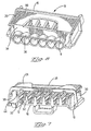
- Figure 6 is an isometric view of a first housing member looking towards the terminal receiving end;
- Figure 7 is an isometric view of the housing member of Figure 6 looking towards the mating end;
- Figure 8 is an isometric view of a terminal position assurance member looking towards the mating end;
- Figure 9 is an isometric view of the terminal position assurance member looking towards the terminal receiving end.
-
- Referring mainly to Figures 3 and 5, an
electrical connector 2 comprises ahousing 4 and terminals 6 (the terminal is shown only partially i.e. without connection end). Thehousing 4 extends from aterminal receiving end 8 to amating end 10. Theconnector 4 is pluggable to a complementary connector (not shown) in a mating direction M. Thehousing 4 is provided withterminal receiving cavities 12 extending from theterminal receiving end 8 to themating end 10 and receiving theterminals 6 therein. Eachterminal 6 is provided with a body 14 having a lockingshoulder 16. - The
housing 4 is provided with afirst housing member 18 and a terminalposition assurance member 20. Thefirst housing member 18 is provided withresilient locking lances 22 integral therewith, in the shape of cantilever beams and having alocking protrusion 24 proximate the free end for engaging thelocking shoulders 16 of the terminals 14 when fully inserted into thecavities 12. As shown in Figure 1, during insertion of theterminal 6 within thehousing cavity 12, thelance 22 is resiliently outwardly biased whereby theprojection 24 rides over the terminal. - Referring to Figures 6 and 7, the
first housing member 18 is shown, and comprises atop wall 26 opposed to a bottom wall 28, and extending therebetween at lateral ends are side-walls 30. Extending from the bottom wall 28 towards thetop wall 26, areseparation walls 32 that define theterminal receiving cavities 12. Theseparation walls 32 do not extend right up to thetop wall 26, thereby leaving a space enabling the terminal position assurance member to be inserted therein. Theseparation walls 32 do not extend right up to themating end 10 of the top and side-walls first housing member 18 further comprises a back or terminal receivingend wall 36 provided with inlets (see Figure 6) 38 to enable insertion of the terminals therethrough into thecavities 12. - Referring to Figures 8 and 9 the terminal
position assurance member 20 comprises theconnector front wall 34, atop wall 38 and side-walls 40. The side-walls 40 are provided withretaining projections 42 that cooperate with corresponding retaining protrusions 44 (see Figure 7) projecting inwardly from the side-walls 30 of thefirst housing member 18. Theretaining protrusions cavities 12. Thefront wall 34 is provided withcutouts 46 to enable insertion of complementary terminals of a complementary connector therethrough. - Referring to Figures 1,2 and 4 the terminal
position assurance member 20 is shown in the pre-assembled position. Themember 20 is assembled into thefirst housing member 18 by sliding it in the mating direction M into the cavity area or gap between theseparation walls 32 and thetop walls 26. In the pre-assembly position, the assurancemember front wall 34 is flush with themating end 10 of the first housing memberouter walls top wall 38 is substantially against the inside of the first housing membertop wall 36. Agap 50 is provided between the assurance member and thelocking lances 22 to enable resilient outward biasing thereof. As can be seen in Figure 9, the terminal position assurance membertop wall 38 is provided with protrusion orwall portions 52 for positioning proximate the locking lances in the fully locked position. - Once all of the terminals have been inserted into the
cavities 12, theposition assurance member 20 is depressed toward thelocking lances 22 to move into the fully locked position as shown in Figure 3, whereby thewall portions 52 are proximate thelocking lances 22 thereby blocking outward biasing thereof. The terminalposition assurance member 20 is held in the fully locked position by engagement of theretention protrusions 42 with theretention protrusions 44 of thefirst housing member 18. - As can be seen in Figures 3 and 4 the first housing member
top wall 26 is provided with acutout 56 that enables depression of the terminal position assurance member into the fully locked position, for example with a finger. As the terminal position assurance member does not have portions projecting outside of thefirst housing member 18, it is protected from accidental displacement by external objects into the fully locked position, for example during handling or transport. In view of the transverse displacement of the terminal position assurance member with respect to thefirst housing member 18, protection is achieved whilst enabling the connector to have amating face 10 of the outer shroud orwalls front wall 34 of the connector. - The terminal position assurance member can be provided with
protrusions 58 that extend through cutouts 60 (see Figures 8 and 6) of the housing membertop wall 26 that indicate that the terminal position assurance member is in the pre-assembly position, or in the locked position. The latter is particularly useful when the terminal position assurance member and housing are of different colors, providing a reliable visual indication of the state of assembly of the connector.
Claims (6)
- A connector comprising a housing (4) having terminal receiving cavities (12) extending therethrough from a terminal receiving end (8) to a mating end (10), and locking lances (22) for locking terminals (6) in the cavities; the connector having a first housing member (18) and a terminal position assurance member (20) mountable in the first housing member in a pre-assembly position such that terminals can be inserted into the housing cavities, and moveable to a fully locked position adjacent the locking lances such that unlocking of the terminals by biasing of the lances is prevented, characterized in that the position assurance member (20) is moveable transversely to a mating direction of the connector from the pre-assembly to the locked position, the position assurance member (20) being surrounded and protected by outer walls (26,30) of the first housing member (18) that prevent external objects from accidentally displacing the assurance member.
- The connector of claim 1 wherein the terminal position assurance member (20) is positioned and spaced above the locking lances (22) in the pre-assembly position, and moveable in a direction theretowards into the locked position.
- The connector of claim 1 or 2 wherein the terminal position assurance member (20) comprises a mating end wall (34) of the connector substantially flush with a mating end (10) of the first housing member (18) .
- The connector of any preceding claim wherein the first housing member has a top wall (26) and side-walls (30) forming an enclosure for surrounding the terminal position assurance member (20).
- The connector of claim 4 wherein in the pre-assembly position, the position assurance member (20) is positioned substantially against an inner surface of the top wall (26).
- The connector of claim 4 or 5 wherein the top wall (26) comprises a cutout (56) to enable passage of a finger therethrough for displacing the assurance member to the locked position.
Applications Claiming Priority (2)
| Application Number | Priority Date | Filing Date | Title |
|---|---|---|---|
| GB9608746 | 1996-04-26 | ||
| GBGB9608746.5A GB9608746D0 (en) | 1996-04-26 | 1996-04-26 | Connector with terminal position assurance member |
Publications (3)
| Publication Number | Publication Date |
|---|---|
| EP0803936A2 EP0803936A2 (en) | 1997-10-29 |
| EP0803936A3 EP0803936A3 (en) | 1999-11-17 |
| EP0803936B1 true EP0803936B1 (en) | 2002-09-25 |
Family
ID=10792751
Family Applications (1)
| Application Number | Title | Priority Date | Filing Date |
|---|---|---|---|
| EP97106358A Expired - Lifetime EP0803936B1 (en) | 1996-04-26 | 1997-04-17 | Connector with terminal position assurance member |
Country Status (5)
| Country | Link |
|---|---|
| US (1) | US5738543A (en) |
| EP (1) | EP0803936B1 (en) |
| JP (1) | JPH1050379A (en) |
| DE (1) | DE69715716T2 (en) |
| GB (1) | GB9608746D0 (en) |
Families Citing this family (8)
| Publication number | Priority date | Publication date | Assignee | Title |
|---|---|---|---|---|
| US6045404A (en) * | 1997-06-30 | 2000-04-04 | The Whitaker Corporation | Electrical connector having a terminal position assurance device |
| US6354873B1 (en) * | 1999-01-29 | 2002-03-12 | Delphi Technologies, Inc. | Snap rail and connector body combination |
| US6126484A (en) * | 1999-11-01 | 2000-10-03 | The Whitaker Corporation | Electrical connector with molded latch stop |
| ITTO20030709A1 (en) * | 2003-09-16 | 2005-03-17 | Framatome Connectors Int | ELECTRIC CONNECTOR |
| KR100809560B1 (en) | 2006-06-19 | 2008-03-04 | 한국몰렉스 주식회사 | TPA installation structure of female connector |
| WO2020176910A1 (en) | 2019-02-25 | 2020-09-03 | J.S.T. Corporation | Method for improving clearance and creepage in a high voltage connector assembly using a male or female terminal position assurance (tpa) device |
| US10892579B2 (en) * | 2019-02-25 | 2021-01-12 | J.S.T. Corporation | Female terminal position assurance (TPA) device for a connector and method for assembling thereof |
| US11605912B2 (en) * | 2021-06-08 | 2023-03-14 | Dinkle Enterprise Co., Ltd. | Terminal block for connecting a circuit board and wires with a slidable fastener on the body |
Family Cites Families (14)
| Publication number | Priority date | Publication date | Assignee | Title |
|---|---|---|---|---|
| US4357066A (en) * | 1980-05-27 | 1982-11-02 | Ford Motor Company | Printed circuit board edge terminal |
| US4431252A (en) * | 1980-05-27 | 1984-02-14 | Ford Motor Company | Printed circuit board edge connector |
| US4343523A (en) * | 1980-05-27 | 1982-08-10 | Ford Motor Company | Printed circuit board edge connector |
| JPH01197979A (en) * | 1988-01-31 | 1989-08-09 | Amp Inc | Double-lock connector |
| JP2700063B2 (en) * | 1989-06-27 | 1998-01-19 | 矢崎総業株式会社 | Electrical connector |
| JPH0758629B2 (en) * | 1989-08-24 | 1995-06-21 | 矢崎総業株式会社 | Connector with terminal locking device |
| JPH079343Y2 (en) * | 1990-04-10 | 1995-03-06 | 矢崎総業株式会社 | Connector with terminal locking device |
| JPH07114131B2 (en) * | 1990-05-16 | 1995-12-06 | 矢崎総業株式会社 | connector |
| US5044991A (en) * | 1990-11-05 | 1991-09-03 | Molex Incorporated | Electrical connector with terminal position assurance component |
| JP2510545Y2 (en) * | 1991-09-04 | 1996-09-11 | 矢崎総業株式会社 | Connector with double locking mechanism for terminals |
| GB9216994D0 (en) * | 1992-08-11 | 1992-09-23 | Amp Gmbh | Electrical connector having secondary locking mechanism |
| US5281168A (en) * | 1992-11-20 | 1994-01-25 | Molex Incorporated | Electrical connector with terminal position assurance system |
| JP2601787Y2 (en) * | 1993-08-31 | 1999-12-06 | 日本エー・エム・ピー株式会社 | connector |
| US5509828A (en) * | 1993-11-25 | 1996-04-23 | Sumitomo Wiring Systems, Ltd. | L-shaped bulb socket |
-
1996
- 1996-04-26 GB GBGB9608746.5A patent/GB9608746D0/en active Pending
-
1997
- 1997-04-01 US US08/831,032 patent/US5738543A/en not_active Expired - Fee Related
- 1997-04-17 DE DE69715716T patent/DE69715716T2/en not_active Expired - Fee Related
- 1997-04-17 EP EP97106358A patent/EP0803936B1/en not_active Expired - Lifetime
- 1997-04-25 JP JP9123258A patent/JPH1050379A/en active Pending
Also Published As
| Publication number | Publication date |
|---|---|
| DE69715716D1 (en) | 2002-10-31 |
| JPH1050379A (en) | 1998-02-20 |
| US5738543A (en) | 1998-04-14 |
| EP0803936A2 (en) | 1997-10-29 |
| EP0803936A3 (en) | 1999-11-17 |
| GB9608746D0 (en) | 1996-07-03 |
| DE69715716T2 (en) | 2003-05-22 |
Similar Documents
| Publication | Publication Date | Title |
|---|---|---|
| EP0726617B1 (en) | Connector with secondary locking and coupling mechanism | |
| US5695368A (en) | Electrical terminal with protected locking lance and a connector therefor | |
| US5281168A (en) | Electrical connector with terminal position assurance system | |
| US4571017A (en) | Electrical connector assembly | |
| KR100198412B1 (en) | Connector with a front end mounted terminal position assurance system | |
| KR100198413B1 (en) | Electrical connector with terminal position gurantee mechanism | |
| US6053753A (en) | Sealed electrical connector assembly | |
| KR20180093810A (en) | Electrical connector with a terminal position assurance device | |
| US5993255A (en) | Electrical connector with combination terminal guide and terminal position assurance member | |
| EP0125786A2 (en) | Electrical connector assembly | |
| EP0976175B1 (en) | Connector with secondary locking and coupling mechanism | |
| EP0963008B1 (en) | A connector and a cap therefor | |
| US6129574A (en) | Connector having a construction for preventing an erroneous assembling of a connector housing and a cover | |
| EP0836251B1 (en) | Electrical connector with shunt | |
| EP0803936B1 (en) | Connector with terminal position assurance member | |
| US5997359A (en) | Electrical connector assembly | |
| US5009615A (en) | Terminal assembly with fixed and flexible tab receptacle retainers | |
| WO2019111094A1 (en) | Connector assembly with independent secondary lock with resilient positioning member | |
| EP0147075B1 (en) | Connector having improved contact retainers | |
| GB2319673A (en) | Connector for airbag | |
| US6206716B1 (en) | Connector | |
| EP1012916B1 (en) | Connector with terminal position assurance member | |
| JPH1050386A (en) | Connector | |
| EP3460922B1 (en) | Connector | |
| EP0992083B1 (en) | Electrical connector having a secondary locking member |
Legal Events
| Date | Code | Title | Description |
|---|---|---|---|
| PUAI | Public reference made under article 153(3) epc to a published international application that has entered the european phase |
Free format text: ORIGINAL CODE: 0009012 |
|
| AK | Designated contracting states |
Kind code of ref document: A2 Designated state(s): DE FR GB IT |
|
| PUAL | Search report despatched |
Free format text: ORIGINAL CODE: 0009013 |
|
| AK | Designated contracting states |
Kind code of ref document: A3 Designated state(s): DE FR GB IT |
|
| 17P | Request for examination filed |
Effective date: 20000508 |
|
| GRAG | Despatch of communication of intention to grant |
Free format text: ORIGINAL CODE: EPIDOS AGRA |
|
| 17Q | First examination report despatched |
Effective date: 20011204 |
|
| GRAG | Despatch of communication of intention to grant |
Free format text: ORIGINAL CODE: EPIDOS AGRA |
|
| GRAH | Despatch of communication of intention to grant a patent |
Free format text: ORIGINAL CODE: EPIDOS IGRA |
|
| GRAH | Despatch of communication of intention to grant a patent |
Free format text: ORIGINAL CODE: EPIDOS IGRA |
|
| GRAH | Despatch of communication of intention to grant a patent |
Free format text: ORIGINAL CODE: EPIDOS IGRA |
|
| GRAA | (expected) grant |
Free format text: ORIGINAL CODE: 0009210 |
|
| AK | Designated contracting states |
Kind code of ref document: B1 Designated state(s): DE FR GB IT |
|
| REG | Reference to a national code |
Ref country code: GB Ref legal event code: FG4D |
|
| REF | Corresponds to: |
Ref document number: 69715716 Country of ref document: DE Date of ref document: 20021031 |
|
| ET | Fr: translation filed | ||
| PLBE | No opposition filed within time limit |
Free format text: ORIGINAL CODE: 0009261 |
|
| STAA | Information on the status of an ep patent application or granted ep patent |
Free format text: STATUS: NO OPPOSITION FILED WITHIN TIME LIMIT |
|
| 26N | No opposition filed |
Effective date: 20030626 |
|
| PGFP | Annual fee paid to national office [announced via postgrant information from national office to epo] |
Ref country code: FR Payment date: 20050418 Year of fee payment: 9 |
|
| PGFP | Annual fee paid to national office [announced via postgrant information from national office to epo] |
Ref country code: IT Payment date: 20060430 Year of fee payment: 10 |
|
| REG | Reference to a national code |
Ref country code: FR Ref legal event code: ST Effective date: 20061230 |
|
| PG25 | Lapsed in a contracting state [announced via postgrant information from national office to epo] |
Ref country code: FR Free format text: LAPSE BECAUSE OF NON-PAYMENT OF DUE FEES Effective date: 20060502 |
|
| PGFP | Annual fee paid to national office [announced via postgrant information from national office to epo] |
Ref country code: DE Payment date: 20080602 Year of fee payment: 12 |
|
| PGFP | Annual fee paid to national office [announced via postgrant information from national office to epo] |
Ref country code: GB Payment date: 20080429 Year of fee payment: 12 |
|
| PG25 | Lapsed in a contracting state [announced via postgrant information from national office to epo] |
Ref country code: IT Free format text: LAPSE BECAUSE OF NON-PAYMENT OF DUE FEES Effective date: 20070417 |
|
| GBPC | Gb: european patent ceased through non-payment of renewal fee |
Effective date: 20090417 |
|
| PG25 | Lapsed in a contracting state [announced via postgrant information from national office to epo] |
Ref country code: DE Free format text: LAPSE BECAUSE OF NON-PAYMENT OF DUE FEES Effective date: 20091103 |
|
| PG25 | Lapsed in a contracting state [announced via postgrant information from national office to epo] |
Ref country code: GB Free format text: LAPSE BECAUSE OF NON-PAYMENT OF DUE FEES Effective date: 20090417 |