EP0974837B1 - Verfahren und Vorrichtung zur zerstörungsfreien Ultraschallprüfung von zu walzendem, noch gut verformbarem Stahl auf Innenfehler - Google Patents
Verfahren und Vorrichtung zur zerstörungsfreien Ultraschallprüfung von zu walzendem, noch gut verformbarem Stahl auf Innenfehler Download PDFInfo
- Publication number
- EP0974837B1 EP0974837B1 EP99109512A EP99109512A EP0974837B1 EP 0974837 B1 EP0974837 B1 EP 0974837B1 EP 99109512 A EP99109512 A EP 99109512A EP 99109512 A EP99109512 A EP 99109512A EP 0974837 B1 EP0974837 B1 EP 0974837B1
- Authority
- EP
- European Patent Office
- Prior art keywords
- ultrasound
- accordance
- roll
- probe
- arrangement
- Prior art date
- Legal status (The legal status is an assumption and is not a legal conclusion. Google has not performed a legal analysis and makes no representation as to the accuracy of the status listed.)
- Expired - Lifetime
Links
Images

Classifications
-
- G—PHYSICS
- G01—MEASURING; TESTING
- G01N—INVESTIGATING OR ANALYSING MATERIALS BY DETERMINING THEIR CHEMICAL OR PHYSICAL PROPERTIES
- G01N29/00—Investigating or analysing materials by the use of ultrasonic, sonic or infrasonic waves; Visualisation of the interior of objects by transmitting ultrasonic or sonic waves through the object
- G01N29/44—Processing the detected response signal, e.g. electronic circuits specially adapted therefor
- G01N29/48—Processing the detected response signal, e.g. electronic circuits specially adapted therefor by amplitude comparison
-
- G—PHYSICS
- G01—MEASURING; TESTING
- G01N—INVESTIGATING OR ANALYSING MATERIALS BY DETERMINING THEIR CHEMICAL OR PHYSICAL PROPERTIES
- G01N29/00—Investigating or analysing materials by the use of ultrasonic, sonic or infrasonic waves; Visualisation of the interior of objects by transmitting ultrasonic or sonic waves through the object
- G01N29/04—Analysing solids
- G01N29/11—Analysing solids by measuring attenuation of acoustic waves
-
- G—PHYSICS
- G01—MEASURING; TESTING
- G01N—INVESTIGATING OR ANALYSING MATERIALS BY DETERMINING THEIR CHEMICAL OR PHYSICAL PROPERTIES
- G01N29/00—Investigating or analysing materials by the use of ultrasonic, sonic or infrasonic waves; Visualisation of the interior of objects by transmitting ultrasonic or sonic waves through the object
- G01N29/22—Details, e.g. general constructional or apparatus details
- G01N29/225—Supports, positioning or alignment in moving situation
-
- G—PHYSICS
- G01—MEASURING; TESTING
- G01N—INVESTIGATING OR ANALYSING MATERIALS BY DETERMINING THEIR CHEMICAL OR PHYSICAL PROPERTIES
- G01N2291/00—Indexing codes associated with group G01N29/00
- G01N2291/04—Wave modes and trajectories
- G01N2291/044—Internal reflections (echoes), e.g. on walls or defects
-
- G—PHYSICS
- G01—MEASURING; TESTING
- G01N—INVESTIGATING OR ANALYSING MATERIALS BY DETERMINING THEIR CHEMICAL OR PHYSICAL PROPERTIES
- G01N2291/00—Indexing codes associated with group G01N29/00
- G01N2291/26—Scanned objects
- G01N2291/263—Surfaces
- G01N2291/2632—Surfaces flat
Definitions
- the invention relates to a method and a device for the non-destructive testing of steel to be rolled, still readily deformable, for internal defects by means of at least one ultrasonic test head.
- the non-destructive material testing by means of ultrasound has been known for a long time.
- DE-PS 32 04 797 describes a method in which a finished workpiece, such as a pipe, is sonicated with a probe, wherein the coupling of the sound energy over a water distance between the head and the workpiece is effected.
- the detection of defects in the workpiece takes place in the so-called pulse-echo method, that is, the sound emitted by the probe is reflected on the one hand on the surface, on the other hand on the rear wall after irradiation of the workpiece. There are thus formed in the display two more or less sharp pulses with a certain amplitude. If the sound wave within the workpiece falls on a defect (crack, inclusion, etc.), it is also reflected at this point, and it forms a third pulse, the error pulse. Since the sound energy repeatedly reciprocates between the defect and the test head, the subject of the cited document is a method with which such additional, non-interest pulses can be hidden, or even pulses resulting from any impurities in Ankoppelmedium.
- the object of the present invention is therefore to be able to detect such defects within the rolling stock in the continuous process during the rolling process. This means that the material to be tested is hot, so that the coupling via grease or oil is not necessarily feasible.
- the steel to be rolled for example in the form of rods, is produced in particular in the continuous casting process in which the emerging from the mold, solidifying strand is guided in an arc in the horizontal to the rolling line.
- existing foreign bodies accumulate in the liquid steel more in the area between the Strand axis and the already solidified lower outer region of the strand.
- these inclusions are to be detected by the method according to the invention during the rolling process.
- this method is performed so that the ultrasonic waves are transmitted by means of an outside of the roller / roll aligned Ultraschallprüfkopfes by serving as a lead line roller / reel body itself or a peripheral part thereof before they hit the test material to be rolled, wherein they are aligned so that they meet there on the roll material surface, where this has the closest contact with the roller, namely, where the maximum backwall echo is achieved.
- test location and the rolling location thus coincide, so that it is possible to react quickly to the detection of significant errors.
- the back wall echo is an indication of this good synchronization between the blocks, it is also possible by the method according to the invention to generate a good synchronization between the blocks by optimizing the back wall echo.
- Another advantage of the method according to the invention is the fact that the lead and Einkoppelrange is formed by the roller / roller itself. This flow or Einkoppelrange is thus suitable because spontaneously changing defects do not occur as in the above-mentioned liquid coupling medium.
- the roll material especially in the peripheral region, particularly fine-grained and lacking in defects.
- the first reflection of the sound waves takes place, the non-reflected portion is refracted to the incidence solder due to the now different propagation velocity, passes through the sample and is reflected at the opposite interface. If defects, in particular inclusions, are present between the first reflection and the back wall echo, the sound waves are also reflected at the latter, as a result of which a pulse of specific amplitude is generated in the receiving part of the test head which lies between the two edge reflection pulses in the amplitude-time diagram.
- the ultrasonic waves are directed onto the rolling material surface in such a way that they are reflected back into the receiver after penetrating the rolling material. As a result, the test material is completely penetrated.
- the test described can be carried out with both normal and SE probes.
- the invention provides that in particular in a Mehrwalzengerüst, in which the disk-shaped rollers / rollers are arranged in a star shape around the nip (so-called Kocksblock), each of these rollers is associated with at least one Ultraschallprüfkopf.
- the arrangement of the probes is made so that the sound wave bundles of all probes capture the entire cross-section of the specimen.
- the device operates even more accurately and effectively when an ultrasonic probe is provided on both sides of each of the disc-shaped rollers.
- circumferential defects in the rolled material can also be detected by directing the ultrasonic waves onto the rolled material surface in such a way that they are reflected in the rolling material near the surface several times along the circumference before they reach the receiver.
- transmitter and receiver are separated.
- the device according to the invention is not limited only to the multi-roll stands just described.
- the probes can also be used in profile rolls, in which the probes are then positioned laterally next to the actual nip in these adjacent profile grooves and through which these grooves and the nip separating from each other rolling stock as a flow path
- This arrangement is suitable for rolls with Flachkantprofil.
- the probes can be positioned on the outer circumference of the rolls, so that the sound passes through the entire roll body before it hits the nip and thus on the rolling stock.
- test heads which sonicate the rolling stock from different sides.
- the at least one ultrasonic probe in the rolling direction and / or perpendicular thereto is pivotable and / or displaceable.
- the at least one probe has a plurality of independently controllable piezoelectric vibrators as a producer of a sound wave front.
- the individual piezoelectric transducers are actuated offset in time from one another. Depending on the time difference results in a sound wave front with different propagation direction.
- the coupling surface of the / the ultrasonic probe (heads) is convex or concave, resulting in a focusing or defocusing of the sound waves.
- the device according to the invention is preferably arranged on a rolling stand preceding the finishing stand of the rolling train.
- the device can work with longitudinal ultrasonic waves but also with transverse ultrasonic waves.
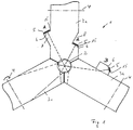
- a three-roll rolling stand is shown schematically and generally provided with the reference numeral 1.
- the coupling surface 6 is realized on the left of the roller 3a by an integrally formed on the side of the roller 3a, wedge-shaped in cross-annular shoulder 7, while on the right by a molded into the roll side (milled) in cross-section wedge-shaped annular groove 8 is realized.
- the orientation of the coupling surfaces 6 is selected in each case so that the sound waves produced and received by the ultrasonic probes 5 of the longitudinal type perpendicular to the rolling gap 2 located in Walzgzut after they have passed through the circumferential part of the roller 3a.
- the propagation direction of the sound waves can also be modified so that they meet at a different angle of 90 ° to the rolling stock and then run close to the specimen under multiple reflection at the interface.
- a third alternative of the coupling of ultrasonic waves is shown in the roller 3b.
- a trapezoidal annular shoulder 9 is placed on the roller side surface, wherein the inclined surface forms the coupling surface 6.
- the positioned at this coupling surface 6 ultrasonic probe 5 emits transverse ultrasonic waves which are refracted at the interface 10 between annular shoulder 9 and roller 3b so that they also meet perpendicular to the Walzgutober Design.
- All three rollers 3a, 3b and 3c can be equipped on both sides with one of these alternatives or else with combinations thereof.
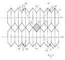
- the arrangement of the ultrasonic probes 5 is shown in a profile rolling mill. It is a Flachkantprofil 11 rolled. In addition to the roll gap 2 forming profile groove are in the roll 3 'further profiled grooves 12, wherein on / in the pointing to the nip 2 profile walls, the ultrasonic probes are arranged, which radiate horizontally through the roll material and arranged the sound propagation direction of both sides of the nip 2 Ultrasonic probes 5 are diametrically opposed.
- the roll gap 2 is formed here by cross-sectional triangular profile grooves 13, wherein in addition to this profile groove 13 more similar profile grooves are provided.
- the ultrasonic probes 5 are located here on the side facing away from the nip 2 side of the profile rollers 3 ', so that the sound waves emitted by them through the entire roller body before they meet perpendicular to the rolling stock.
- the ultrasonic probes 5 are preferably positioned on different sides of the roll gap 2 on / in the flanks 14 of the profile grooves.
- the probes 5 are arranged stationarily, while the rollers 3, 3 'or the coupling surfaces 6 pass the test head. Between the test head 5 and coupling surface 6 is a water film 15th
- the Einkoppelort the sound waves in the rolling stock to be tested is preferably located immediately behind the inlet point of the rolling stock in the nip, ie where roller and Walzgutober Design are in intimate contact with each other.
- test device is arranged on a rolling mill, which is positioned in the rolling process in front of the finishing stand.
Landscapes
- Physics & Mathematics (AREA)
- Analytical Chemistry (AREA)
- Health & Medical Sciences (AREA)
- Life Sciences & Earth Sciences (AREA)
- Chemical & Material Sciences (AREA)
- Biochemistry (AREA)
- General Health & Medical Sciences (AREA)
- General Physics & Mathematics (AREA)
- Immunology (AREA)
- Pathology (AREA)
- Signal Processing (AREA)
- Engineering & Computer Science (AREA)
- Acoustics & Sound (AREA)
- Investigating Or Analyzing Materials By The Use Of Ultrasonic Waves (AREA)
Description
- Die Erfindung betrifft ein Verfahren und eine Vorrichtung zur zerstörungsfreien Prüfung von zu walzendem, noch gut verformbarem Stahl auf Innenfehler mittels mindestens eines Ultraschallprüfkopfes.
- Die zerstörungsfreie Werkstoffprüfung mittels Ultraschall ist seit langem bekannt.
- So ist beispielsweise in der
DE-PS 32 04 797 ein Verfahren beschrieben, bei dem ein fertiges Werkstück, beispielsweise ein Rohr, mit einem Prüfkopf beschallt wird, wobei die Ankopplung der Schallenergie über eine Wasserstrecke zwischen Kopf und Werkstück bewirkt wird. - Die Detektion von Fehlstellen im Werkstück erfolgt im sogenannten Impuls-Echo-Verfahren, das heißt, daß der vom Prüfkopf ausgesendete Schall zum einen an der Oberfläche, zum anderen an der Rückwand nach Durchstrahlung des Werkstücks reflektiert wird. Es bilden sich in der Anzeige somit zwei mehr oder weniger scharfe Impulse mit bestimmter Amplitude. Fällt die Schallwelle innerhalb des Werkstücks auf eine Fehlstelle (Riß, Einschluß, etc.), wird sie auch an dieser Stelle reflektiert, und es bildet sich ein dritter Impuls, der Fehlerimpuls. Da die Schallenergie mehrfach zwischen Fehlstelle und Prüfkopf hin- und herläuft, ist Gegenstand der zitierten Druckschrift ein Verfahren, mit dem derartige zusätzliche, nicht interessierende Impulse ausgeblendet werden können, bzw. auch Impulse, die von eventuellen Verunreinigungen im Ankoppelmedium herrühren. Die
- Prüfung findet an einem fertigen Werkstück statt unter Benutzung eines flüssigen Ankoppelmediums, in welchem - wie erwähnt - ebenfalls Fremdkörper, die die Messungen stören, vorhanden sein können.
- Zusätzlich wird noch die
US-A 3 620 061 genannt, in der eine Vorrichtung beschrieben ist, die aus einer Walze besteht, in die ein Ultraschallsender eingebaut ist. Zweck dieser Vorrichtung ist jedoch durch Erzeugung von Vibrationen eine Entlastung beim Walzvorgang selbst. Die Ultraschallwellen dienen somit nicht dazu, das Walzgut zu durchdringen und auf etwaige Innenfehler zu untersuchen. - Schließlich muss noch die
US-A 3 401 547 erwähnt werden, in der ein Verfahren beschrieben wird, bei dem mittels Ultraschallwellen zu walzendes Material auf die korrekte Dicke überprüft wird. Es ist zwar dort auch schon darauf hingewiesen worden, dass auch Störungen im Metall dabei detektiert werden. Die Ultraschallköpfe sind jedoch bei der dort vorgestellen Vorrichtung innerhalb der Walzen angeordnet, was den Nachteil hat, dass die Prüfköpfe schwer zugänglich sind und auch individuell nicht ausgerichtet und verstellt werden können. Zudem wird als Ankoppelmedium Fett oder Öl vorgeschlagen, was unter Kostengesichtspunkten und Gesichtspunkten des Umweltschutzes bedenklich ist. - Gegenstand der vorliegenden Erfindung ist es daher, im kontinuierlichen Verfahren während des Walzprozesses derartige Fehler innerhalb des Walzgutes aufspüren zu können. Das heißt, daß das zu prüfende Material heiß ist, so dass die Ankopplung über Fett oder Öl nicht unbedingt machbar ist.
- Der zu walzende Stahl, beispielsweise in Form von Stäben, wird insbesondere im Kokillen-Stranggießverfahren hergestellt, bei dem der aus der Kokille heraustretende, sich verfestigende Strang in einem Bogen in die Horizontale zur Walzstrecke geführt wird. Infolge der Schwerkraft reichern sich im flüssigen Stahl vorhandene Fremdkörper mehr im Bereich zwischen der Strangachse und dem bereits verfestigten unteren Außenbereich des Stranges an.
- Insbesondere diese Einschlüsse gilt es mit dem erfindungsgemäßen Verfahren während des Walzprozesses zu detektieren.
- Gemäß Patentanspruch 1 wird dieses Verfahren so geführt, daß die Ultraschallwellen mittels eines außen an der Walze/Rolle ausgerichteten Ultraschallprüfkopfes durch den als Vorlaufstrecke dienenden walzen-/Rollenkörper selbst oder einen umfangnahen Teil davon gesendet werden, bevor sie auf das zu prüfende Walzmaterial treffen, wobei sie derart ausgerichtet werden, dass sie dort auf die Walzmaterialoberfläche treffen, wo dieses den innigsten Kontakt mit der Walze aufweist, dort nämlich, wo das maximale Rückwandecho erzielt wird.
- Der Prüfort und der Walzort fallen somit zusammen, so daß bei der Aufspürung signifikanter Fehler schnell reagiert werden kann.
- Es wird angestrebt, daß die Ultraschallwellen dort auf die Walzmaterialoberfläche auftreffen, wo noch intensiv in radialer Richtung verformt wird, d.h. im Bereich der Einlaufstelle des Walzgutes in das Walzgerüst. Versuche haben gezeigt, daß ein maximales Rückwandecho erzielt wird, wenn das Walzgut keinerlei Zug unterworfen ist, d.h. weiterhin, daß eine gute Synchronisation zwischen den Walzblöcken gewährleistet sein muß.
- Da das Rückwandecho ein Indiz für diese gute Synchronisation zwischen den Blöcken ist, besteht durch die erfindungsgemäße Methode ebenfalls die Möglichkeit, durch Optimierung des Rückwandechos eine gute Synchronisation zwischen den Blöcken zu generieren.
- Ein weiterer Vorteil des erfindungsgemäßen Verfahrens ist darin zu sehen, daß die Vorlauf- und Einkoppelstrecke durch die Walze/Rolle selbst gebildet wird. Diese Vorlauf- oder Einkoppelstrecke ist somit geeignet, da spontan wechselnde Fehlstellen wie in dem oben erwähnten flüssigen Einkoppelmedium nicht auftreten. Darüber hinaus ist das Walzenmaterial, insbesondere im umfangnahen Bereich, besonders feinkörnig und fehlstellenarm.
- An der Grenzfläche von relativ kalter Walze/Rolle zu heißem Stahl findet die erste Reflektion der Schallwellen statt, der nicht reflektierte Anteil wird aufgrund der nun anderen Ausbreitungsgeschwindigkeit zum Einfallslot gebrochen, durchläuft den Prüfling und wird an der gegenüberliegenden Grenzfläche reflektiert. Befinden sich zwischen erster Reflektion und Rückwandecho Fehlstellen, insbesondere Einschlüsse, werden die Schallwellen auch an diesen reflektiert, wodurch im Empfangsteil des Prüfkopfs ein Impuls bestimmter Amplitude erzeugt wird, der im Amplituden-Zeit-Diagramm zwischen den beiden Randreflektionsimpulsen liegt.
- Die Ultraschallwellen werden derart auf die Walzmaterialoberfläche gerichtet, daß sie nach Durchdringen des Walzmaterials in sich zum Empfänger zurückreflektiert werden. Hierdurch wird das Prüfmaterial vollständig durchschallt. Die beschriebene Prüfung ist sowohl mit Normal- als auch S-E-Prüfköpfen durchführbar.
- Da Fehlstellen im Randbereich infolge der endlichen Breite des Reflektionsimpulses mittels eines Prüfkopfes, der longitudinale Schallwellen aussendet, die lotrecht auf die Walzgutoberfläche treffen und darüber hinaus nur einen Teilbereich des Prüflings durchstrahlen, nicht detektiert werden können, ist erfindungsgemäß vorgesehen, daß insbesondere in einem Mehrwalzengerüst, bei dem die scheibenförmigen Walzen/Rollen sternförmig um den Walzspalt herum angeordnet sind (sogenannter Kocksblock), jeder dieser Walzen mindestens ein Ultraschallprüfkopf zugeordnet ist. Die Anordnung der Prüfköpfe wird so getroffen, daß die Schallwellenbündel aller Prüfköpfe den gesamten Querschnitt des Prüflings erfassen.
- Noch genauer und effektiver arbeitet die Vorrichtung, wenn auf beiden Seiten jeder der scheibenförmigen Walzen/Rollen ein Ultraschallprüfkopf vorgesehen ist.
- Umfangsnahe Fehler im Walzmaterial können jedoch auch dadurch aufgespürt werden, daß die Ultraschallwellen derart auf die Walzmaterialoberfläche gerichtet sind, daß sie im Walzmaterial oberflächennah mehrfach entlang dem Umfang reflektiert werden, bevor sie zum Empfänger gelangen.
- Hierbei sind Sender und Empfänger getrennt voneinander.
- Zur Positionierung der Prüfköpfe sind seitlich an den scheibenförmigen Walzen/Rollen entweder im Querschnitt keilförmige Ringnuten eingefräst oder im Querschnitt keilförmige Ringschultern angeformt. Die zum Walzenumfang zeigende Nutfläche bzw. Schulterfläche bewegt sich während des Walzens unter der Detektorfläche des stationären Prüfkopfes vorbei, wobei lediglich ein geringer, mit Wasser gefüllter Spalt zwischen Kopf und Walze vorhanden ist.
- Die erfindungsgemäße Vorrichtung ist jedoch nicht nur auf die eben beschriebene Mehrwalzengerüste beschränkt. Es können die Prüfköpfe auch bei Profilwalzen eingesetzt werden, bei denen dann die Prüfköpfe seitlich neben den eigentlichen Walzspalt in diesen benachbarten Profilnuten positioniert sind und das diese Nuten und den Walzspalt voneinander trennende Walzmaterial als Vorlaufstrecke durchstrahlen
- Dabei weisen jeweils zwei auf verschiedenen Seiten des Walzspalts angeordnete Ultraschallprüfköpfe einander diametral entgegengesetzte Schallausbreitungsrichtungen auf.
- Diese Anordnung bietet sich bei Walzen mit Flachkantprofil an.
- Bei Walzen mit Spießkantprofil können die Prüfköpfe am Außenumfang der Walzen positioniert sein, so daß der Schall den gesamten Walzenkörper durchläuft, bevor er auf den Walzspalt und somit auf das Walzgut trifft.
- Auch hierbei können mehrere Prüfköpfe vorgesehen sein, die das Walzgut von verschiedenen Seiten beschallen.
- Als besonders geeignete Prüfköpfe bei den bisher beschriebenen Anwendungen haben sich solche mit Piezoschwinger als Schallerzeuger erwiesen.
- Zur Einstellung der Beschallungsrichtung kann vorgesehen sein, daß der mindestens eine Ultraschall-Prüfkopf in Walzrichtung und/oder senkrecht dazu verschwenkbar und/oder verschiebbar ist.
- Eine Alternative hierzu schlägt vor, daß der mindestens eine Prüfkopf eine Vielzahl von unabhängig voneinander ansteuerbaren Piezoschwingern als Erzeuger einer Schallwellenfront aufweist.
- Die einzelnen Piezoschwinger werden zeitlich versetzt zueinander angesteuert. Abhängig von der Zeitdifferenz ergibt sich eine Schallwellenfront mit unterschiedlicher Ausbreitungsrichtung.
- Es kann vorgesehen sein, daß die Ankoppelfläche des/der Ultraschall-Prüfkopfes(-Köpfe) konvex oder konkav gewölbt ist, wodurch sich eine Fokussierung bzw. Defokussierung der Schallwellen ergibt.
- Vorzugsweise wird die erfindungsgemäße Vorrichtung an einem dem Fertiggerüst der Walzstraße vorausgehenden Walzgerüst angeordnet.
- An dieser Stelle liegt eine gute Verformbarkeit des Walzgutes vor. Besonders wichtig ist es jedoch, daß hier die Vorrichtung nur einmal justiert zu werden braucht, so daß der Montage- und Justieraufwand auf ein Minimum reduziert wird.
- Die Vorrichtung kann mit longitudinalen Ultraschallwellen aber auch mit transversalen Ultraschallwellen arbeiten.
- Das ist insbesondere von Vorteil, da durch entsprechende Verläufe des Ultraschalls bei entsprechender Wahl der Einstrahlwinkel sowohl mittels transversaler als auch mittels longitudinaler Wellen randnahe Fehler, die radial verlaufen, detektiert werden können.
- Die Erfindung wird im folgenden anhand einer Zeichnung dargestellt und näher erläutert.
- Es zeigen:
- Fig. 1:
- in abgebrochener Darstellung ein Mehrwalzengerüst mit drei verschiedenen Alternativen der Anordnung von Ultraschallprüfköpfen,
- Fig. 2:
- in schematischer Darstellung die Anordnung von Ultraschallprüfköpfen bei Profilwalzen (Flachkant),
- Fig. 3:
- in schematischer Darstellung die Anordnung von Ultraschallprüfköpfen bei Profilwalzen (Spießkant).
- In der Fig. 1 ist schematisch ein Dreiwalzen-Walzgerüst dargestellt und allgemein mit dem Bezugszeichen 1 versehen.
- Sternförmig um den in diesem Beispiel kreisförmigen Walzspalt 2 herum sind drei scheibenförmige Walzen 3a, 3b, 3c angeordnet, wobei die Drehachsen der Walzen mit 4 bezeichnet sind.
- Bei der Walze 3a sind zwei alternative Anordnungen von lediglich schematisch dargestellten Ultraschallprüfköpfen 5 gezeigt. Die Einkoppelfläche 6 ist links an der Walze 3a durch eine an die Seite der Walze 3a angeformte, im Querschnitt keilförmige Ringschulter 7 verwirklicht, während sie rechts durch eine in die Walzenseite eingeformte (eingefräste) im Querschnitt keilförmige Ringnut 8 verwirklicht ist.
- Die Orientierung der Einkoppelflächen 6 ist jeweils so gewählt, daß die von den Ultraschall-Prüfköpfen 5 erzeugten und empfangenen Schallwellen longitudinaler Art lotrecht auf das im Walzspalt 2 befindliche Walzgzut treffen, nachdem sie den umfangsnahen Teil der Walze 3a durchlaufen haben.
- Wie bei der Walze 3c lediglich angedeutet kann die Ausbreitungsrichtung der Schallwellen auch so modifiziert werden, daß sie in einem von 90° verschiedenen Winkel auf die Walzgutoberfläche treffen und dann im Prüfling randnah unter mehrfacher Reflektion an der Grenzfläche verlaufen.
- Eine dritte Alternative der Einkopplung von Ultraschallwellen ist bei der Walze 3b dargestellt. Hierbei ist auf die Walzenseitenfläche eine im Querschnitt trapezförmige Ringschulter 9 aufgesetzt, wobei die schräge Fläche die Einkoppelfläche 6 bildet. Der an dieser Einkoppelfläche 6 positionierte Ultraschall-Prüfkopf 5 sendet transversale Ultraschallwellen aus, die an der Grenzfläche 10 zwischen Ringschulter 9 und Walze 3b so gebrochen werden, daß sie ebenfalls lotrecht auf die Walzgutoberfläche treffen.
- Alle drei Walzen 3a, 3b und 3c können beidseitig mit einer dieser Alternativen ausgestattet sein oder aber auch mit Kombinationen derselben.
- In der Fig. 2 ist die Anordnung der Ultraschall-Prüfköpfe 5 in einer Profilwalzanlage dargestellt. Es wird ein Flachkantprofil 11 gewalzt. Neben der den Walzspalt 2 bildenden Profilnut befinden sich in der Walze 3' weitere Profilnuten 12, wobei an/in den auf den Walzspalt 2 weisenden Profilwänden die Ultraschall-Prüfköpfe angeordnet sind, die das Walzenmaterial horizontal durchstrahlen und die Schallausbreitungsrichtung der beidseitig des Walzspalts 2 angeordneten Ultraschall-Prüfköpfe 5 diametral entgegengesetzt sind.
- In der Fig. 3 schließlich ist die Anordnung der Ultraschall-Prüfköpfe 5 an einem Profilwalzsystem dargestellt, das Spießkantprofile walzt.
- Der Walzspalt 2 wird hier durch im Querschnitt dreieckförmige Profilnuten 13 gebildet, wobei neben dieser Profilnut 13 weitere gleichartige Profilnuten vorgesehen sind.
- Die Ultraschall-Prüfköpfe 5 befinden sich hier auf der vom Walzspalt 2 abgewandten Seite der Profilwalzen 3', so daß die von ihnen ausgesandten Schallwellen den gesamten Walzenkörper durchstrahlen, bevor sie lotrecht auf das Walzgut treffen.
- Die Ultraschall-Prüfköpfe 5 sind dabei auf verschiedenen Seiten des Walzspalts 2 vorzugsweise an/in den Flanken 14 der Profilnuten positioniert.
- In allen beschriebenen Fällen sind die Prüfköpfe 5 stationär angeordnet, während die Walzen 3, 3' bzw. die Einkoppelfächen 6 am Prüfkopf vorbeilaufen. Zwischen Prüfkopf 5 und Einkoppelfläche 6 befindet sich ein Wasserfilm 15.
- Der Einkoppelort der Schallwellen in das zu prüfende Walzgut befindet sich vorzugsweise unmittelbar hinter der Einlaufstelle des Walzguts in den Walzspalt, also dort, wo Walze und Walzgutoberfläche in innigem Kontakt miteinander sind.
- Dabei ist die Prüfvorrichtung an einem Walzgerüst angeordnet, welches im Walzablauf vor dem Fertiggerüst positioniert ist.
Claims (16)
- Verfahren zur zerstörungsfreien Prüfung beim Walzvorgang von zu walzendem, noch gut verformbaren Stahl auf Innenfehler mittels mindestens eines außen an der Walze/Rolle angeordneten Ultraschall-Prüfkopfes (5), der aus einem Ultraschallsender und einem Ultraschallempfänger besteht, bei welchem die Ultraschallwellen durch den als Vorlaufstrecke dienenden Walzen-/Rollenkörper (3a, 3b, 3c, 3') selbst oder einen umfangnahen Teil davon gesendet werden, bevor sie auf das zu prüfende Walzmaterial treffen, wobei sie derart ausgerichtet werden, dass sie dort auf die Walzmaterialoberfläche treffen, wo dieses den innigsten Kontakt mit der Walze/Rolle aufweist, dort nämlich, wo das maximale Rückwandecho erzielt wird, den zu prüfenden Stahl durchlaufen und von dem Ultraschallempfänger detektiert werden.
- Verfahren nach Anspruch 1,
dadurch gekennzeichnet,
dass die Ultraschallwellen derart auf die Walzmaterialoberfläche treffen, dass sie nach Durchdringen des Walzmaterials in sich zum Empfänger zurückreflektiert werden. - Verfahren nach Anspruch 1,
dadurch gekennzeichnet,
dass die Ultraschallwellen derart auf die Walzmaterialoberfläche gerichtet sind, dass sie im Walzmaterial oberflächennah mehrfach entlang dem Umfang reflektiert werden, bevor sie zum Empfänger gelangen. - Verfahren nach einem der Ansprüche 1 bis 3,
dadurch gekennzeichnet,
dass der mindestens eine Ultraschallprüfkopf longitudinale Ultraschallwellen aussendet. - Verfahren nach einem der Ansprüche 1 bis 3,
dadurch gekennzeichnet,
dass der mindestens eine Ultraschallprüfkopf transversale Ultraschallwellen aussendet. - Vorrichtung zur zerstörungsfreien Prüfung beim Walzvorgang von zu walzendem, noch gut verformbaren Stahl auf Innenfehler mittels mindestens eines Ultraschallprüfkopfes (5), der aus einem Ultraschallsender und einem Ultraschallempfänger besteht,
dadurch gekennzeichnet,
dass der mindestens eine Ultraschall-Prüfkopf auβen an mindestens einer der am Walzvorgang beteiligten Walzen/Rollen (3a, 3b, 3c, 3') angeordnet ist, derart, dass der Walzen/Rollenkörper selbst oder ein umfangnaher Teil davon die Vorlaufstrecke für die Ultraschallwellen bildet, bevor sie auf das zu prüfende Walzmaterial treffen, und der mindestens eine Ultraschall-Prüfkopf (5) als Sender und/oder Empfänger ausgebildet ist und seine Ausrichtung derart wählbar ist, dass die Ultraschallwellen dort auf die Walzmaterialoberfläche treffen, wo dieses den innigsten Kontakt mit der Walze/Rolle (3a, 3b, 3c, 3') aufweist, wobei der mindestens eine Ultraschall-Prüfkopf (5) in Walzrichtung und/oder senkrecht dazu verschwenkbar und/oder verschiebbar ist und sich zwischen Ultraschall-Prüfkopf (5) und der ihm zugeordneten Walze/Rolle (3a, 3b, 3c, 3') bzw. der Ankoppelfläche ein Wasserfilm (15) befindet. - Vorrichtung nach Anspruch 6,
dadurch gekennzeichnet,
dass die Walzvorrichtung ein Mehrwalzengerüst ist, bei dem die scheibenförmigen Walzen/Rollen (3a, 3b, 3c,) sternförmig um den Walzspalt (2) herum angeordnet sind und jeder dieser Walzen/Rollen (3a, 3b, 3c) mindestens ein Ultraschallprüfkopf (5) zugeordnet ist. - Vorrichtung nach Anspruch 7,
dadurch gekennzeichnet,
dass auf jeder Seite jeder Walze/Rolle (3a, 3b, 3c) mindestens ein Ultraschall-Prüfkopf (5) angeordnet ist. - Vorrichtung nach einem der Ansprüche 6 bis 8,
dadurch gekennzeichnet,
dass der/die Ultraschall-Prüfkopf (-Köpfe) (5) in seitlich in die Walzen/Rollen (3a,3b, 3c, 3') eingeformten Ringnuten (8) positioniert ist/sind. - Vorrichtung nach einem der Ansprüche 6 bis 8,
dadurch gekennzeichnet,
dass der/die Ultraschall-Prüfkopf (-Köpfe) (5) auf seitlich an die Walzen/Rollen (3a, 3b, 3c) angeformten ringschulterartigen Vorsprüngen (7) positioniert ist/sind. - Vorrichtung nach Anspruch 6,
dadurch gekennzeichnet,
dass die Walzvorrichtung aus zwei Profilwalzen (3') besteht und der/die Ultraschall-Prüfkopf (-Köpfe) (5) seitlich so angeordnet ist/sind, dass die Schallwellen im rechten Winkel auf die durch das Profil gebildete Walzspalt-Wand (2) ausgerichtet sind. - Vorrichtung nach Anspruch 11,
dadurch gekennzeichnet,
dass jeweils zwei auf verschiedenen Seiten des Walzspaltes (2) angeordnete Ultraschall-Prüfköpfe (5) einander diametral entgegengesetzte Schallausbreitungsrichtung aufweisen. - Vorrichtung nach einem der Ansprüche 6 bis 12,
dadurch gekennzeichnet,
dass der mindestens eine Prüfkopf (5) einen Piezoschwinger als Schallerzeuger aufweist. - Vorrichtung nach einem der Ansprüche 6 bis 13,
dadurch gekennzeichnet,
dass der mindestens eine Prüfkopf (5) eine Vielzahl von unabhängig voneinander ansteuerbaren Piezoschwingern als Erzeuger einer Schallwellenfront aufweist. - Vorrichtung nach einem der Ansprüche 6 bis 14,
dadurch gekennzeichnet,
dass die Ankoppelfläche des/der Ultraschall-Prüfkopfes (-köpfe) (5) konvex oder konkav gewölbt ist. - Vorrichtung nach einem der Ansprüche 6 bis 15,
gekennzeichnet durch
die Anordnung an einem dem Fertiggerüst der Walzstraße vorausgehenden Walzgerüst.
Applications Claiming Priority (4)
| Application Number | Priority Date | Filing Date | Title |
|---|---|---|---|
| DE19833386 | 1998-07-24 | ||
| DE19833386 | 1998-07-24 | ||
| DE19915203A DE19915203C2 (de) | 1998-07-24 | 1999-04-03 | Verfahren und Vorrichtung zur zerstörungsfreien Prüfung von zu walzendem, noch gut verformbarem Stahl auf Innenfehler |
| DE19915203 | 1999-04-03 |
Publications (3)
| Publication Number | Publication Date |
|---|---|
| EP0974837A2 EP0974837A2 (de) | 2000-01-26 |
| EP0974837A3 EP0974837A3 (de) | 2001-10-31 |
| EP0974837B1 true EP0974837B1 (de) | 2007-07-18 |
Family
ID=26047676
Family Applications (1)
| Application Number | Title | Priority Date | Filing Date |
|---|---|---|---|
| EP99109512A Expired - Lifetime EP0974837B1 (de) | 1998-07-24 | 1999-05-12 | Verfahren und Vorrichtung zur zerstörungsfreien Ultraschallprüfung von zu walzendem, noch gut verformbarem Stahl auf Innenfehler |
Country Status (7)
| Country | Link |
|---|---|
| US (1) | US6105408A (de) |
| EP (1) | EP0974837B1 (de) |
| JP (1) | JP3469133B2 (de) |
| AT (1) | ATE367579T1 (de) |
| DE (1) | DE59914412D1 (de) |
| DK (1) | DK0974837T3 (de) |
| ES (1) | ES2291005T3 (de) |
Families Citing this family (4)
| Publication number | Priority date | Publication date | Assignee | Title |
|---|---|---|---|---|
| KR100400184B1 (ko) * | 1997-10-31 | 2003-10-01 | 제이에프이 스틸 가부시키가이샤 | 원기둥체 표면의 초음파 탐상방법과 그 탐상장치및 이를 이용한 롤의 연삭방법 |
| DE102005044760B3 (de) * | 2005-09-20 | 2007-04-12 | Georgsmarienhütte Gmbh | Vorrichtung zur Ultraschallprüfung von heißem Walzmaterial |
| US8920320B2 (en) * | 2006-03-10 | 2014-12-30 | Liposonix, Inc. | Methods and apparatus for coupling a HIFU transducer to a skin surface |
| US20110077514A1 (en) | 2009-09-29 | 2011-03-31 | Medicis Technologies Corporation | Variable treatment site body contouring using an ultrasound therapy device |
Family Cites Families (11)
| Publication number | Priority date | Publication date | Assignee | Title |
|---|---|---|---|---|
| US3620061A (en) * | 1969-10-03 | 1971-11-16 | Us Navy | Design of ultrasonic transducers for use with rolling mill rolls |
| ZA822586B (en) * | 1981-05-06 | 1983-03-30 | Automation Ind Inc | An ultrasonic rail testing method and system |
| DE3204797C2 (de) * | 1982-02-11 | 1983-12-29 | Nukem Gmbh, 6450 Hanau | Impuls-Echo-Verfahren zur zerstörungsfreien Ultraschall-Werkstoffprüfung |
| GB2137344A (en) * | 1983-03-16 | 1984-10-03 | Standard Telephones Cables Ltd | Flaw protection in wire drawing |
| FR2580813B1 (fr) * | 1985-04-17 | 1987-07-03 | Aerospatiale | Dispositif de controle par ultra-sons pourvu d'un organe de roulement |
| US4927299A (en) * | 1987-05-21 | 1990-05-22 | Regents Of The University Of Minnesota | Integral acoustic emission sensor for manufacturing processes and mechanical components |
| FR2629586B1 (fr) * | 1988-03-30 | 1992-01-03 | Cezus Co Europ Zirconium | Procede de controle ultrasonore de l'epaisseur de placage d'un tube metallique, dispositif correspondant et application a des tubes en alliage de zr plaque |
| US5048340A (en) * | 1988-05-23 | 1991-09-17 | Iowa State University Research Foundation, Inc. | Semi-automatic system for ultrasonic measurement of texture |
| DE3905956A1 (de) * | 1989-02-25 | 1990-09-13 | Fraunhofer Ges Forschung | Vorrichtung zur messung von ultraschallaufzeiten |
| DE9110922U1 (de) * | 1991-06-21 | 1992-10-22 | Siemens Ag, 8000 Muenchen | Inspektion einer dynamoelektrischen Maschine in einem Spalt zwischen Stator und Rotor |
| GB9323482D0 (en) * | 1993-11-13 | 1994-01-05 | Palmer Stuart B | Electromagnetic acoustic transducers |
-
1999
- 1999-05-12 DK DK99109512T patent/DK0974837T3/da active
- 1999-05-12 DE DE59914412T patent/DE59914412D1/de not_active Expired - Lifetime
- 1999-05-12 ES ES99109512T patent/ES2291005T3/es not_active Expired - Lifetime
- 1999-05-12 EP EP99109512A patent/EP0974837B1/de not_active Expired - Lifetime
- 1999-05-12 AT AT99109512T patent/ATE367579T1/de active
- 1999-06-18 US US09/335,667 patent/US6105408A/en not_active Expired - Lifetime
- 1999-07-22 JP JP20762499A patent/JP3469133B2/ja not_active Expired - Fee Related
Non-Patent Citations (1)
| Title |
|---|
| None * |
Also Published As
| Publication number | Publication date |
|---|---|
| EP0974837A2 (de) | 2000-01-26 |
| JP2000046805A (ja) | 2000-02-18 |
| ATE367579T1 (de) | 2007-08-15 |
| EP0974837A3 (de) | 2001-10-31 |
| DK0974837T3 (da) | 2007-10-29 |
| JP3469133B2 (ja) | 2003-11-25 |
| ES2291005T3 (es) | 2008-02-16 |
| DE59914412D1 (de) | 2007-08-30 |
| US6105408A (en) | 2000-08-22 |
Similar Documents
| Publication | Publication Date | Title |
|---|---|---|
| EP0577599B1 (de) | Ultraschall-messverfahren für den wanddickenverlauf einer schweissnaht eines rohres | |
| EP1102033B1 (de) | Verfahren und Vorrichtung zur berührungslosen online Heisswanddickenmessung an Rohren | |
| DE102010025144A1 (de) | Berührungslose Rohrwanddickenmessvorrichtung und Rohrwanddickenmessung | |
| DE4027161A1 (de) | Vorrichtung zur pruefung von laenglichen gegenstaenden mittels ultraschallwellen | |
| DE69908117T2 (de) | Verfahren zur überwachung des abstandes zwischen den walzen eines walzenpaares und mittel zur durchführung des verfahrens | |
| EP1733224B1 (de) | Verfahren und vorrichtung zur ultraschallprüfung von oberflächenfehlern, wie bspw. risse, ausbrüche u. dgl. an einer walze eines walzwerks | |
| DE10224635A1 (de) | Verfahren und Vorrichtung zur Bestimmung der Exzentrizität eines Hohlblockes | |
| DE102012112121B4 (de) | Verfahren und Vorrichtung zur zerstörungsfreien Prüfung eines rotationssymmetrischen Werkstücks, welches Abschnitte verschiedener Durchmesser aufweist | |
| EP1378299A1 (de) | Verfahren und Vorrichtung zur Bestimmung der Exzentrizität eines Hohlblocks | |
| DE19915203C2 (de) | Verfahren und Vorrichtung zur zerstörungsfreien Prüfung von zu walzendem, noch gut verformbarem Stahl auf Innenfehler | |
| DE2118595B2 (de) | Vorrichtung zur Ultraschall-Werkstoffprüfung auf in einem Werkstück enthaltene Fehlerstellen | |
| EP0974837A2 (de) | Verfahren und Vorrichtung zur zerstörungsfreien prüfung von zu walzendem, noch gut verformbarem Stahl auf Innenfehler | |
| DE69025037T2 (de) | Ultraschallprüfverfahren zur Feststellung von Fehlstellen in Kugeln und Vorrichtung dazu | |
| DE102005009482B3 (de) | Verfahren und Vorrichtung zur Überwachung des Fertigungsprozesses zur Herstellung von warmgefertigten Rohren aus Stahl | |
| DE102005043122A1 (de) | Verfahren und Einrichtung zur Ultraschallprüfung eines Werkstückes mit einer unebenen Oberfläche | |
| DE102012112120B4 (de) | Verfahren und Vorrichtung zur oberflächennahen zerstörungsfreien Prüfung eines rotationssymmetrischen Werkstücks mit abschnittsweise wechselndem Durchmesser mittels Ultraschall | |
| AT515767B1 (de) | Materialprüfungsverfahren, Verwendung einer Ziehsteinanordnung und Ziehsteinanordnung | |
| DE102005044760B3 (de) | Vorrichtung zur Ultraschallprüfung von heißem Walzmaterial | |
| WO2007147765A1 (de) | Verfahren und vorrichtung zur prozesskontrolle beim walzen von metallen | |
| DE102009040748B4 (de) | Vorrichtung zur zerstörungsfreien Prüfung von Schweißnähten in Werkstücken mittels Ultraschall | |
| WO2007147764A1 (de) | Verfahren und vorrichtung zur zustandsüberwachung von walzen | |
| DE4239159C2 (de) | Vorrichtung zum zerstörungsfreien Messen der Dicke einer Härteschicht | |
| CH668484A5 (de) | Verfahren zur ultraschallpruefung von werkstuecken. | |
| DE19804298B4 (de) | Verfahren zur Ultraschallprüfung mit Echostart und Vorrichtung hierfür | |
| DE102012112119A1 (de) | Verfahren und Vorrichtung zur oberflächennahen zerstörungsfreien Prüfung eines rotationssymmetrischen Werkstücks mit abschnittsweise wechselndem Durchmesser mittels Ultraschall |
Legal Events
| Date | Code | Title | Description |
|---|---|---|---|
| PUAI | Public reference made under article 153(3) epc to a published international application that has entered the european phase |
Free format text: ORIGINAL CODE: 0009012 |
|
| AK | Designated contracting states |
Kind code of ref document: A2 Designated state(s): AT BE CH CY DE DK ES FI FR GB GR IE IT LI LU MC NL PT SE Kind code of ref document: A2 Designated state(s): AT BE CH DE DK ES FI FR GB GR IT LI LU NL PT SE |
|
| AX | Request for extension of the european patent |
Free format text: AL;LT;LV;MK;RO;SI |
|
| PUAL | Search report despatched |
Free format text: ORIGINAL CODE: 0009013 |
|
| AK | Designated contracting states |
Kind code of ref document: A3 Designated state(s): AT BE CH CY DE DK ES FI FR GB GR IE IT LI LU MC NL PT SE |
|
| AX | Request for extension of the european patent |
Free format text: AL;LT;LV;MK;RO;SI |
|
| RIC1 | Information provided on ipc code assigned before grant |
Free format text: 7G 01N 29/10 A, 7G 01N 29/04 B |
|
| 17P | Request for examination filed |
Effective date: 20020129 |
|
| AKX | Designation fees paid |
Free format text: AT BE CH DE DK ES FI FR GB GR IT LI LU NL PT SE |
|
| 17Q | First examination report despatched |
Effective date: 20041115 |
|
| GRAP | Despatch of communication of intention to grant a patent |
Free format text: ORIGINAL CODE: EPIDOSNIGR1 |
|
| RIC1 | Information provided on ipc code assigned before grant |
Ipc: G01N 29/04 20060101ALI20070109BHEP Ipc: G01N 29/22 20060101AFI20070109BHEP |
|
| RTI1 | Title (correction) |
Free format text: METHOD AND DEVICE FOR THE NONDESTRUCTIVE ULTRASONIC TESTING OF STEEL TO BE ROLLED, IN A STILL EASILY DEFORMABLE STATE |
|
| GRAS | Grant fee paid |
Free format text: ORIGINAL CODE: EPIDOSNIGR3 |
|
| GRAA | (expected) grant |
Free format text: ORIGINAL CODE: 0009210 |
|
| AK | Designated contracting states |
Kind code of ref document: B1 Designated state(s): AT BE CH DE DK ES FI FR GB GR IT LI LU NL PT SE |
|
| REG | Reference to a national code |
Ref country code: GB Ref legal event code: FG4D Free format text: NOT ENGLISH |
|
| REG | Reference to a national code |
Ref country code: CH Ref legal event code: EP |
|
| REF | Corresponds to: |
Ref document number: 59914412 Country of ref document: DE Date of ref document: 20070830 Kind code of ref document: P |
|
| RAP2 | Party data changed (patent owner data changed or rights of a patent transferred) |
Owner name: GEORGSMARIENHUETTE GMBH |
|
| REG | Reference to a national code |
Ref country code: PT Ref legal event code: SC4A Free format text: AVAILABILITY OF NATIONAL TRANSLATION Effective date: 20071004 |
|
| REG | Reference to a national code |
Ref country code: SE Ref legal event code: TRGR |
|
| GBT | Gb: translation of ep patent filed (gb section 77(6)(a)/1977) |
Effective date: 20071003 |
|
| REG | Reference to a national code |
Ref country code: PT Ref legal event code: TE4A Owner name: GEORGSMARIENHUETTE GMBH, DE Effective date: 20071008 |
|
| REG | Reference to a national code |
Ref country code: DK Ref legal event code: T3 |
|
| REG | Reference to a national code |
Ref country code: CH Ref legal event code: PFA Owner name: GEORGSMARIENHUETTE GMBH Free format text: GEORGSMARIENHUETTE GMBH#KLOECKNERSTRASSE 30#49124 GEORGSMARIENHUETTE (DE) -TRANSFER TO- GEORGSMARIENHUETTE GMBH#NEUE HUETTENSTRASSE 1#49124 GEORGSMARIENHUETTE (DE) Ref country code: CH Ref legal event code: NV Representative=s name: ISLER & PEDRAZZINI AG |
|
| REG | Reference to a national code |
Ref country code: GR Ref legal event code: EP Ref document number: 20070403087 Country of ref document: GR |
|
| NLT2 | Nl: modifications (of names), taken from the european patent patent bulletin |
Owner name: GEORGSMARIENHUETTE GMBH Effective date: 20071017 |
|
| ET | Fr: translation filed | ||
| REG | Reference to a national code |
Ref country code: ES Ref legal event code: FG2A Ref document number: 2291005 Country of ref document: ES Kind code of ref document: T3 |
|
| PLBE | No opposition filed within time limit |
Free format text: ORIGINAL CODE: 0009261 |
|
| STAA | Information on the status of an ep patent application or granted ep patent |
Free format text: STATUS: NO OPPOSITION FILED WITHIN TIME LIMIT |
|
| 26N | No opposition filed |
Effective date: 20080421 |
|
| PGFP | Annual fee paid to national office [announced via postgrant information from national office to epo] |
Ref country code: GB Payment date: 20140528 Year of fee payment: 16 |
|
| PGFP | Annual fee paid to national office [announced via postgrant information from national office to epo] |
Ref country code: FI Payment date: 20140530 Year of fee payment: 16 Ref country code: IT Payment date: 20140528 Year of fee payment: 16 Ref country code: AT Payment date: 20140527 Year of fee payment: 16 Ref country code: FR Payment date: 20140530 Year of fee payment: 16 Ref country code: PT Payment date: 20140512 Year of fee payment: 16 Ref country code: ES Payment date: 20140527 Year of fee payment: 16 Ref country code: GR Payment date: 20140527 Year of fee payment: 16 Ref country code: LU Payment date: 20140604 Year of fee payment: 16 Ref country code: SE Payment date: 20140527 Year of fee payment: 16 Ref country code: CH Payment date: 20140527 Year of fee payment: 16 Ref country code: NL Payment date: 20140528 Year of fee payment: 16 Ref country code: DE Payment date: 20140526 Year of fee payment: 16 |
|
| PGFP | Annual fee paid to national office [announced via postgrant information from national office to epo] |
Ref country code: DK Payment date: 20140528 Year of fee payment: 16 |
|
| PGFP | Annual fee paid to national office [announced via postgrant information from national office to epo] |
Ref country code: BE Payment date: 20140630 Year of fee payment: 16 |
|
| REG | Reference to a national code |
Ref country code: PT Ref legal event code: MM4A Free format text: LAPSE DUE TO NON-PAYMENT OF FEES Effective date: 20151112 |
|
| REG | Reference to a national code |
Ref country code: DE Ref legal event code: R119 Ref document number: 59914412 Country of ref document: DE |
|
| REG | Reference to a national code |
Ref country code: DK Ref legal event code: EBP Effective date: 20150531 |
|
| REG | Reference to a national code |
Ref country code: CH Ref legal event code: PL |
|
| REG | Reference to a national code |
Ref country code: AT Ref legal event code: MM01 Ref document number: 367579 Country of ref document: AT Kind code of ref document: T Effective date: 20150512 |
|
| GBPC | Gb: european patent ceased through non-payment of renewal fee |
Effective date: 20150512 |
|
| PG25 | Lapsed in a contracting state [announced via postgrant information from national office to epo] |
Ref country code: CH Free format text: LAPSE BECAUSE OF NON-PAYMENT OF DUE FEES Effective date: 20150531 Ref country code: LU Free format text: LAPSE BECAUSE OF NON-PAYMENT OF DUE FEES Effective date: 20150512 Ref country code: FI Free format text: LAPSE BECAUSE OF NON-PAYMENT OF DUE FEES Effective date: 20150512 Ref country code: LI Free format text: LAPSE BECAUSE OF NON-PAYMENT OF DUE FEES Effective date: 20150531 Ref country code: IT Free format text: LAPSE BECAUSE OF NON-PAYMENT OF DUE FEES Effective date: 20150512 Ref country code: GR Free format text: LAPSE BECAUSE OF NON-PAYMENT OF DUE FEES Effective date: 20151208 |
|
| REG | Reference to a national code |
Ref country code: NL Ref legal event code: MM Effective date: 20150601 |
|
| REG | Reference to a national code |
Ref country code: FR Ref legal event code: ST Effective date: 20160129 |
|
| PG25 | Lapsed in a contracting state [announced via postgrant information from national office to epo] |
Ref country code: SE Free format text: LAPSE BECAUSE OF NON-PAYMENT OF DUE FEES Effective date: 20150513 Ref country code: AT Free format text: LAPSE BECAUSE OF NON-PAYMENT OF DUE FEES Effective date: 20150512 Ref country code: PT Free format text: LAPSE BECAUSE OF NON-PAYMENT OF DUE FEES Effective date: 20151112 |
|
| REG | Reference to a national code |
Ref country code: GR Ref legal event code: ML Ref document number: 20070403087 Country of ref document: GR Effective date: 20151208 |
|
| PG25 | Lapsed in a contracting state [announced via postgrant information from national office to epo] |
Ref country code: DE Free format text: LAPSE BECAUSE OF NON-PAYMENT OF DUE FEES Effective date: 20151201 Ref country code: DK Free format text: LAPSE BECAUSE OF NON-PAYMENT OF DUE FEES Effective date: 20150531 Ref country code: GB Free format text: LAPSE BECAUSE OF NON-PAYMENT OF DUE FEES Effective date: 20150512 Ref country code: NL Free format text: LAPSE BECAUSE OF NON-PAYMENT OF DUE FEES Effective date: 20150601 |
|
| PG25 | Lapsed in a contracting state [announced via postgrant information from national office to epo] |
Ref country code: FR Free format text: LAPSE BECAUSE OF NON-PAYMENT OF DUE FEES Effective date: 20150601 |
|
| REG | Reference to a national code |
Ref country code: ES Ref legal event code: FD2A Effective date: 20170203 |
|
| PG25 | Lapsed in a contracting state [announced via postgrant information from national office to epo] |
Ref country code: ES Free format text: LAPSE BECAUSE OF NON-PAYMENT OF DUE FEES Effective date: 20150513 |
|
| PG25 | Lapsed in a contracting state [announced via postgrant information from national office to epo] |
Ref country code: BE Free format text: LAPSE BECAUSE OF NON-PAYMENT OF DUE FEES Effective date: 20150531 |