EP0974448A1 - A tyre manufacturing process and apparatus - Google Patents
A tyre manufacturing process and apparatus Download PDFInfo
- Publication number
- EP0974448A1 EP0974448A1 EP99113761A EP99113761A EP0974448A1 EP 0974448 A1 EP0974448 A1 EP 0974448A1 EP 99113761 A EP99113761 A EP 99113761A EP 99113761 A EP99113761 A EP 99113761A EP 0974448 A1 EP0974448 A1 EP 0974448A1
- Authority
- EP
- European Patent Office
- Prior art keywords
- drum
- profile
- lateral
- receiving surface
- carcass reinforcement
- Prior art date
- Legal status (The legal status is an assumption and is not a legal conclusion. Google has not performed a legal analysis and makes no representation as to the accuracy of the status listed.)
- Granted
Links
Images


Classifications
-
- B—PERFORMING OPERATIONS; TRANSPORTING
- B29—WORKING OF PLASTICS; WORKING OF SUBSTANCES IN A PLASTIC STATE IN GENERAL
- B29D—PRODUCING PARTICULAR ARTICLES FROM PLASTICS OR FROM SUBSTANCES IN A PLASTIC STATE
- B29D30/00—Producing pneumatic or solid tyres or parts thereof
- B29D30/06—Pneumatic tyres or parts thereof (e.g. produced by casting, moulding, compression moulding, injection moulding, centrifugal casting)
- B29D30/08—Building tyres
- B29D30/20—Building tyres by the flat-tyre method, i.e. building on cylindrical drums
- B29D30/24—Drums
- B29D30/244—Drums for manufacturing substantially cylindrical tyre components with cores or beads, e.g. carcasses
- B29D30/248—Drums of the undercut type without toroidal expansion, e.g. with provisions for folding down the plies, for positioning the beads under the surface of the drum
-
- B—PERFORMING OPERATIONS; TRANSPORTING
- B29—WORKING OF PLASTICS; WORKING OF SUBSTANCES IN A PLASTIC STATE IN GENERAL
- B29D—PRODUCING PARTICULAR ARTICLES FROM PLASTICS OR FROM SUBSTANCES IN A PLASTIC STATE
- B29D30/00—Producing pneumatic or solid tyres or parts thereof
- B29D30/06—Pneumatic tyres or parts thereof (e.g. produced by casting, moulding, compression moulding, injection moulding, centrifugal casting)
- B29D30/08—Building tyres
- B29D30/20—Building tyres by the flat-tyre method, i.e. building on cylindrical drums
- B29D30/32—Fitting the bead-rings or bead-cores; Folding the textile layers around the rings or cores
- B29D2030/3214—Locking the beads on the drum; details of the drum in the bead locking areas, e.g. drum shoulders
-
- B—PERFORMING OPERATIONS; TRANSPORTING
- B29—WORKING OF PLASTICS; WORKING OF SUBSTANCES IN A PLASTIC STATE IN GENERAL
- B29D—PRODUCING PARTICULAR ARTICLES FROM PLASTICS OR FROM SUBSTANCES IN A PLASTIC STATE
- B29D30/00—Producing pneumatic or solid tyres or parts thereof
- B29D30/06—Pneumatic tyres or parts thereof (e.g. produced by casting, moulding, compression moulding, injection moulding, centrifugal casting)
- B29D30/08—Building tyres
- B29D30/20—Building tyres by the flat-tyre method, i.e. building on cylindrical drums
- B29D30/32—Fitting the bead-rings or bead-cores; Folding the textile layers around the rings or cores
- B29D2030/3221—Folding over means, e.g. bladders or rigid arms
- B29D2030/3228—Folding over means, e.g. bladders or rigid arms using one bladder acting on each side of the drum
-
- B—PERFORMING OPERATIONS; TRANSPORTING
- B29—WORKING OF PLASTICS; WORKING OF SUBSTANCES IN A PLASTIC STATE IN GENERAL
- B29D—PRODUCING PARTICULAR ARTICLES FROM PLASTICS OR FROM SUBSTANCES IN A PLASTIC STATE
- B29D30/00—Producing pneumatic or solid tyres or parts thereof
- B29D30/06—Pneumatic tyres or parts thereof (e.g. produced by casting, moulding, compression moulding, injection moulding, centrifugal casting)
- B29D30/08—Building tyres
- B29D30/20—Building tyres by the flat-tyre method, i.e. building on cylindrical drums
- B29D30/32—Fitting the bead-rings or bead-cores; Folding the textile layers around the rings or cores
- B29D2030/3221—Folding over means, e.g. bladders or rigid arms
- B29D2030/3235—Folding over means, e.g. bladders or rigid arms using two or more bladders acting on each side of the drum
Definitions
- the present invention relates to a method of manufacturing tires and drums assembly allowing the implementation of the process.
- the invention relates more particularly to the manufacture of tires comprising a carcass reinforcement and, in the beads, at least one reinforcing rod around which the carcass reinforcement is wound up forming a reversal so that, contrary to what is generally carried out, the inversion of the carcass reinforcement is disposed between the rod and the carcass reinforcement itself.
- Certain manufacturing processes use assembly drums having in particular shoulders against which the rod is brought in describing an axial movement.
- the rod is held against the shoulder by simply gluing the products together or by a accessory device.
- Such drums can directly use rods or semi-finished products manufactured separately and constituted by the rod radially surmounted by a rubber mix profile.
- rod-complex a rod single or a rod surmounted by a rubber mix profile, comprising optionally additionally a rod coating product such as another mixing profile rubbery or a rubber mat comprising cables.
- Patent application EP 99/107552 filed on April 15, 1999 describes a drum with two grooves for positioning a rod, and designed for production of such a tire, as well as a suitable method. This drum belongs to the category of drums sometimes called flat drums.
- Patent application BP 99/107551 filed April 15, 1999 describes a drum similar to the previous one, except that it is specially designed for the manufacture of a tire with rods of diameters different in each of the beads.
- the invention aims to propose, still for the manufacture of a tire using rod complexes and in which the inversion of the carcass reinforcement is positioned between the rod and said frame, assembly drums of the so-called “semi-core” type ", Also called” shoulders ", that is to say drums devoid of throats positioning for rods.
- the invention also provides suitable methods for these shoulder drums.
- both sides of the drum are designed the same way, so that the other of the lateral ends of the carcass reinforcement is also placed vertically of one and cantilevered with respect to another first cylindrical bearing surface, arranged axially on the other side, also coaxial and of diameter smaller than the surface of main reception.
- the end of the carcass reinforcement is raised radially by pressing radially outward in an area of said end located axially externally to the rubber mix profile.
- the invention also finds advantage in being used when the the tire beads are symmetrical or have different diameters.
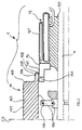
- the apparatus 1 comprises an assembly drum 10 mounted on a shaft 11, a device roll-up 12, a device (not shown) for feeding the translatable rod-complex axially to and from the drum 10, leaving free the volume inside the rod complexes.
- the rod complex feeding device can take the form by example of a ring carrying rod complex attachment fingers, or of a ring with magnetic attachment or a crown.
- the equipment also includes a device comprising folding fingers 13, shown diagrammatically in FIG. 4B. This last can be integrated with the rod complex supply device.
- the rolling-up device 12 disposed axially outside the drum 10, comprises a support 122 slidably mounted on the shaft 11.
- the roll-up device 12 also includes inflatable membranes 121 carried by said support 122.
- the assembly drum 10 has a main receiving surface 101, generally cylindrical, and has at least one shoulder 102.
- the main receiving surface 101 consists of segments 103 juxtaposed circumferentially in the working position of the drum and mounted, by means of rods 105, with radial displacement relative to supports 104, mounted on the shaft 11.
- the segments 103 make it possible to retract radially the drum 10 for the extraction (axially) of the carcasses produced on said drum.
- the segments 103 constitute a system of several adjacent segments circumferentially, the circumferentially lateral faces of some (B) being converging inside the drum (let's call them by convention “the vaults”), and the faces circumferentially side of the others (A) being convergent outside the drum (let's call them by convention "the keys”).
- the vaults the circumferentially lateral faces of some (B) being converging inside the drum (let's call them by convention “the vaults”), and the faces circumferentially side of the others (A) being convergent outside the drum (let's call them by convention "the keys”).
- This drum 10 therefore has only one radial working position used for the assembly of a tire casing, and a single retracted position for extraction of the carcass.
- the drum 10 also has a lateral protuberance 106 integral with said drum 10 and fixed on the latter, having a generally cylindrical support surface 107, of diameter lower than that of the main receiving surface 101, so that the shoulder 102 remains cleared to allow the installation of the rod complex on said shoulder by a lateral approach.
- the shape of the radial section of the segments 103 i.e. the shape of the surface exterior constituted by the main receiving surface 101 extended by the shoulders 102 may vary somewhat. For example, it may be less square at the shoulders, as appears for example in US Patent 1,911,594. That is to say that the shoulders may be slightly inclined with respect to the radial direction, without presenting of portion included in a plane perpendicular to the axis. Seen in radial section, the shoulders are then bent enough, while keeping rounded connections.
- the apparatus 1 also includes a crown lateral 14 (14 ') coaxial with said drum 10, having a bearing surface 141 (141') generally cylindrical, with a diameter smaller than that of the lateral protuberance 106. This lateral crown 14 is (14 ') mounted on the shaft 11 and is axially movable relative to the drum 10, as explained below.
- the side ring 14 is mounted on the device rolling up 12 axially internally with respect to the center of the apparatus 1, and is secured in axial translation of said device
- the diameter of the bearing surface 141 of the lateral crown 14 is less than the internal diameter of the segments 103 in their position of work to allow its retraction under said segments.
- the axial displacement of the rolling-up device 12 makes it possible, in fact, to actuate the lateral crown 14 between a transversely advanced position, shown in Figure 1, where the latter exceeds axially of the drum 10 and a retracted position where the lateral ring 14 is hidden by the drum 10.
- the lateral crown 14 ′ is mounted on the assembly drum 10 radially under the lateral protuberance 106, and with possible axial translation relative to the segments 103 between an advanced position where it protrudes axially relative to the lateral protuberance 106 at above the roll-up device 12 and a retracted position under the lateral protuberance 106.
- This arrangement allows the length of the membrane actually used to be adjusted. for rolling up, the lateral crown 14 'being susceptible, during the movement of axial sliding, partially covering the roll-up device. Indeed, during a expansion of the rolling-up membranes 121, the lateral crown 14 'being in position advanced, the membranes do not act on the products placed on the lateral protuberance 106 as will be seen in more detail in the description of the manufacturing process.
- the different means used to control the rotation around the axis of rotation of the various elements of the apparatus do not require detailed explanations. Let's point out simply that it is necessary to control in rotation not only the drum 10, but also preferably the roll-up device 12 because it also serves as a laying surface for various constituent products of the tire to be manufactured.
- the rotation control of the rolling-up device 12 can come directly from the shaft 11, or else the device for rolling up can be engaged on demand on the drum 10, for example by a chamber inflatable tubular 109 inserted on the bearing surface 141, on the axially inner side of this one.
- the clutch of the rolling-up device 12 is then inflated.
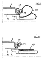
- FIGS. 4A to 4J schematically illustrate this method in the first embodiment of the invention according to the first variant of the apparatus 1 shown in Figure 1, the setting implementing the method with the second variant of the apparatus 1 easily deduced from this one.
- the drum 10 being in the working position and the lateral crown 14 in deployed position, that is to say axially separated, it is deposited on the receiving surface main 101 a rubber tablecloth called the NI "inner tablecloth”, then a textile cables, called “carcass ply” NC. All of these NI and NC layers constitute what is collectively called here “carcass reinforcement” A.
- the end A 'of the carcass reinforcement A protrudes axially from the main receiving surface 101 and overhangs the lateral protuberance 106 and the lateral crown 14, as well as part of the roll-up membranes.
- the end A ′ of the carcass reinforcement A is then folded radially inwards, on respectively the bearing surface 107 of the lateral protuberance 106, the bearing surface 141 of the lateral crown 14 and partially on the membranes 121 using the fingers of folding down 13, as shown in FIG. 4B.
- the carcass ply can also be laid in slight tension.
- the propensity for the resulting shrinkage spontaneously causes diametrical retension of ends A ', which can be completed by a folding down as described above or a rolling, to correctly apply said carcass reinforcement to the surfaces of reception and support.
- a rubber mix profile is deposited.
- This profile P1 has in the example described a front section the shape of a quadrilateral but we can consider other forms of section.
- the roll-up membranes are then inflated, which raise the end A 'situated radially. axially externally to the lateral crown 14 and therefore to the profile P1. So the area of the raised end A 'rotates around the profile P1 so that the latter is oriented substantially radially, as shown in Figures 4D and 4E. Note at passage that at least the portion of the membranes 121 in contact with the carcass reinforcement A is chosen and / or treated so that the carcass reinforcement A does not stick to said portion (for example example because its surface is covered with a suitable textile fabric).
- the roll-up membranes 121 are then deflated, the raised end A ′ remaining in its substantially radially oriented position, and is brought together axially, thanks to the rod-complex supply device, a rod-complex CT.
- the rod complex CT is constituted in this example by a rod T of section square, made of wires or cables, radially surmounted by a mixing profile rubbery P2.
- the CT rod complex is brought axially until it is pressed against the end AT'. We then continue the axial approximation of the rod complex CT thus entraining with it the end A 'which is turned over, and passing above the section P1 covered by a part of the end A '. The CT rod complex is thus brought together until it comes into contact with the shoulder 102 via the inverted end A ′, which is thus found between the rod T and the carcass reinforcement A, as seen in FIG. 4G.
- the deposit of the rod rod complex CT on the inversion of the end A 'of the reinforcement carcass A is thus carried out directly above the second cylindrical bearing surface 107 coaxial, disposed between the main receiving surface 101 and the first bearing surface 141 (or 141 '), the diameter of the main receiving surface 101 being greater than that of the second bearing surface, itself greater than the diameter of the first bearing surface (see also 741, 711, 751 below).
- the lateral crown 14 is then moved axially towards the center (plane CP), which retracts under the lateral protuberance 106 the first bearing surface 141 (141 'in the variant illustrated in Figure 3), so that the section P1 surrounded by the carcass reinforcement A is now just over the rolling membranes 121 (Figure 4H).
- the roll-up membranes 121 are inflated again, this time making a tilting of the profile P1 (FIG. 4I) against the rod complex, or at least which raises it radially somewhat from the rod rod complex and help to press it laterally against the CT rod complex.
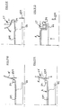
- the apparatuses 5, 6, 7 respectively comprise an assembly drum 50, 60, 70, radially expandable, comprises a central body 51, 61, 71 mounted on a shaft 52, 62, 72, having a receiving surface 511, 611, 711 of the products to be assembled and the shoulders 514, 614, 714.
- These devices 5, 6, 7 also include a system for feeding the rod complexes, not shown, axially translatable to the drum 50, 60, 70 leaving the diameter free interior of the rod complexes as described for the previous example. But unlike in the previous example, the devices 5, 6, 7 are used here without folding fingers, as will be understood on reading the manufacturing process using these equipment.
- drums 50, 60, 70 described in this exemplary embodiment of the invention being symmetrical with respect to a plane P represented in FIGS. 5, 6, 7, we will not describe in the following the description as the half-drums located to the right of the plane P in said figures.
- the choice of drums described here does not limit the scope of the invention to drums symmetrical.
- the central body 51 (61, 71) comprises an axially displaceable half-body 512 (612, 712) around the shaft 52 (62, 72) in order to adjust the spacing of the bead wires of the tire to be produced, and a central ring 513 (613, 713) fixed axially relative to the shaft 52 (62, 72).
- the half-body 512 (612, 712) and the central crown 513 (613, 713) are constituted by a plurality of lateral segments 522 (622, 722) and central 523 (623, 723) respectively in vis-a-vis.
- the lateral segments 522 (622, 722) are juxtaposed circumferentially around of the shaft 52 (62, 72) and, similarly, the central segments 523 (623, 723) are juxtaposed circumferentially around the shaft 52 (62, 72).
- each lateral segment 522 (622, 722) is guided relative to the central segment 523 (623, 723) opposite by means of a rod 515 (615, 715), one of which end crosses the central segment 523 (623, 723) and the other end of which is mounted at sliding in a bore 516 (616, 716) carried by the lateral segment 522 (622, 722) in vis-a-vis.
- the segments 522 (622, 722) are radially movable under the action of an inflatable expansion chamber 517 (617, 717) disposed under said lateral segments 522 (622, 722). Lateral segments 522 (622, 722) entrain in their radial movement the central segments 523 (623, 723) of the central crown 513 (613, 713), which are integral in radial displacement with the segments lateral 522 (622, 722) via the rods 515 (615, 715).
- Platelets 518 (618, 718) are fixed by screws on the segments 523 (623, 723) of the central crown 513 (613, 713). These plates 518 (618, 718) cover at least partially the segments 522 (622, 722) of the half-body 512 (612, 712) in order to ensure a continuity between the central crown 513 (613, 713) and said half-body 512 (612, 712) for the products to be assembled regardless of the axial position of the half-body 512 (612, 712).
- the central crown 513 (613, 713) also makes it possible to ensure axial retention of the inserts 518 (618, 718) during the radial expansion of the drum 50 (60, 70). Of course, we can consider elements other than expansion chambers in order to achieve expansion radial of the drum.
- the receiving surface 511 (611, 711) of the products to be assembled is thus constituted by all the external surfaces of the plates 518 (618, 718) and of the zones of the segments 522 (622, 722) not covered by said plates 518 (618, 718).
- the drum 50 (60) has a radially expandable lateral protuberance 54 (64), integral with the body 51 (61) and having a bearing surface 541 (641) of the products to to assemble.
- the lateral protuberance 54 (64) is juxtaposed coaxially with the shoulder 514 (614) of the body 51 (61) and forms a bearing surface 541 (641) of diameter smaller than that of said main receiving surface 511 (611).
- a possible realization of the protuberance lateral 54 (64) consists in forming it in the form of segments respectively coming in extension of the segments 522 (622) of the half-body 512 (612). We can also, without depart from the scope of the invention, consider that the lateral protuberance 54 (64) is an element reported relative to body 51 (61).
- the apparatus 5 (6) comprises a rolling-up device 55 (65) mounted on the shaft 52 (62) axially externally to the lateral protuberance 54 (64).
- This roll-up device 55 (65) can be constituted, as in the example of the apparatus 1, by membranes of roll up.
- a roll-up device 55 (65) has been chosen comprising lifting fingers; the term “finger” is understood to mean a profile of small cross section.
- the roll-up device 55 (65) is independent of the drum 50 (60) and can be axially translated, however it can also be envisaged that this device is integral with the drum 50 (60) in which case it is advantageous to use the segments 522 (622) of the half-body (512, 612) as respective supports for the lifting fingers.
- the roll-up device 55 (65) therefore comprises a plurality of lifting fingers 551 (651), of rectangular section (if seen radially), distributed circularly around the shaft 52 (62) and extending in radial directions.
- lifting fingers 551 (651) are arranged axially outwardly relative to the center of drum 50 (60), a short distance from the free end of the lateral protuberance 54 (64), and respectively have a contact surface 552 (652) of the products to to assemble.
- the lifting fingers 551 (651) are mounted with possible radial displacement respectively on a cylindrical support 553 (653) mounted in axial translation on the shaft 52 (62) by means of cylinders 554 (654).
- each lifting finger 551 (651) carries an axial extension 558 (658) on which is fixed, by means of screws, the jack 554 (654) corresponding which slides radially in a housing 555 (655) carried by the cylindrical support 553 (653).
- the lifting fingers 551 (651) can be deployed radially outwards from the drum 50 (60) from a rest position to a deployed position. And, in order to ensure the return of the lifting fingers 551 (651) to the rest position, an elastic belt of recall 559 (659) surrounds all of the axial extensions 558 (658).
- lifting fingers 551 thus offer the products to be assembled a plurality of contact surfaces 552 (652) discontinuous and distributed circumferentially.
- the free ends of the lifting fingers 551 (651), that is to say radially external to the drum 50 (60), are constituted by a roller 557 (657) mounted free in rotation about an axis and which thus carries the contact surface 552 (652).
- This pebble 557 (657) avoids creating tension in the products raised during deployment of the lifting fingers 551 (651) ensuring, in this phase, a contact "Rolling" between fingers and products.
- the drum 50 carries expansion means 57, which comprise in particular the expansion chambers 517, towards two distinct expanded positions and which allow to reach its two positions successively.
- expansion means 57 comprise in particular the expansion chambers 517
- the drum can take three distinct stable positions, characterized by three circumferential developments different than a rope wrapped around the main receiving surface.
- the expansion means 57 comprise a ring Control 572 mounted on a support ring 573, the two rings being mounted on the shaft 52 and disposed axially outside the body 51 near the free end of the lateral protuberance 54.
- the support ring 573 carries an inner cylindrical shoulder 573 'which cooperates with the control ring 572.
- the control ring 572 is rotatably mounted relative to the body 51 of the drum 50, the support ring 573 being integral in rotation with said body 51.
- the lateral protuberance 54 carries at least one pin engagement 542 in a cam 574 carried by the control ring 572 and, simultaneously, in a light 575 oriented in a radial direction and carried by the support ring 573.
- each of the segments constituting the protuberance side 54 carries an engagement pin in a cam and a corresponding light.
- the expanded position accessible to the drum 51 is dependent on the angular position of the control ring 572. Indeed, depending on the rotation of the control ring 572 and therefore from its angular position and that of the cams 574, the engagement pins 542 have a different radial positioning range, which therefore limits the radial expansion of the drum 50, the slots 575 ensuring the radially guiding of the engagement pins 542.
- each cam 574 has a shape resembling a Z, the possible positions of the corresponding engagement pin 542 in each side of the Z corresponding to the three positions of the drum 50, that is to say one position retracted, an intermediate expanded position and a maximum expanded position.
- the drum 50 being in the contracted position, the surface of reception 511 the layers NI and NC constituting the carcass reinforcement A.
- the end A 'of the carcass reinforcement extends axially from the receiving surface 511 and covers the lateral protuberance 54 as well as the lifting fingers 551 of the roll-up device 55.
- the end A ′ of the carcass reinforcement A is then folded over respectively the bearing surface 541 of the lateral protuberance 541 by making a first expansion of the drum 50 thanks to the control rings 572 and support 573.
- the expansion of the drum 50 in the intermediate position makes it possible to press the end A ′ on the bearing surface 541 and that formed by the contact surfaces 557 of the roll up 55.
- the rubber mix profile is deposited P1 on the area of the end A ′ of the carcass reinforcement A disposed on the bearing surface 541 of the lateral protuberance 54.
- the lifting fingers 551 are then deployed radially to the deployed position in which the contact surfaces 557 substantially constitute a cylindrical surface of diameter greater than the diameter of the bearing surface 541 so that the fingers 551 are raised radially the end A 'located axially outside the lateral protuberance 54 and therefore to profile P1.
- the raised end area A ' rotates around the profile P1 so that the latter is oriented substantially radially, as shown in the Figure 10D.
- the rod complex is brought together axially, thanks to the rod-complex supply device CT until pressing on the latter from end A '.
- the lifting fingers 551 can be recalled in the rest position thanks to the elastic belt 559 and we continue the axial approximation of the rod complex CT thus resulting with it the end A 'which is turned over, and passing above the section P1 covered by a part of the end A ', as seen in Figure 10F. Note, however, that we can also recall fingers 551 before pressing the end A 'on the rod complex.
- the control ring is then actuated simultaneously in advance of the rod complex CT 572 in order to bring the drum 50 into its maximum expanded position.
- the radial expansion of the resulting bearing surface 541 raises radially the profile P1 relative to the CT rod complex (see Figure 10G).
- the apparatus 6 comprises in addition to the elements already described (namely the drum 60, the shaft 62, the lateral protuberance 64 integral with the drum 60 and the roll-up device 65) an axially movable ferrule 66, for example mounted on the shaft 62.
- This ferrule 66 has a diameter substantially identical to that of the receiving surface 611 and is mounted, in a translatable manner relative to the shaft 62, between a retracted position and a position for covering the surface 641 of the lateral protuberance 64 in which the ferrule 66 covers said surface 541 as shown in FIG. 6.
- the presence of the ferrule 66 provides a firm support for the installation of a rubber mix profile.
- the ferrule 66 is carried by a support 67 mounted on the shaft 62.
- the support 67 comprises a outer ring 671, concentric with the shaft 62 and which covers the ferrule 66 in the position retracted from the latter.
- the diameter of the outer ring 671 is chosen closest possible from that of ferrule 66, to allow the passage of the rod complex above of the outer ring.
- the support 67 is mounted axially displaceable on the shaft 62 so in particular, to facilitate disassembly operations or access to the drum 60.
- the support 67 carries a chamber annular 672 concentric with the shaft 62 inside which axially slides a piston 673 for actuating the ferrule 66, connected to the latter by a connecting rod 674, rotatably mounted around the axis 674A, itself mounted on the support 67.
- the connection of the connecting rod 674 with the ferrule 66 is produced by mounting an axis integral with a bearing 675, said penetrating axis in an elongated orifice 674B arranged at one end of the rod 674.
- the bearing 675 is also sliding relative to the outer ring 671, which provides guidance in translation of the ferrule 66.
- the drum 60 has in this example only two working positions: a position retracted corresponding to the deflated position of the inflation bladder expansion chamber 617 and an expanded position to the inflated position of the expansion chamber 617.
- a position retracted corresponding to the deflated position of the inflation bladder expansion chamber 617 and an expanded position to the inflated position of the expansion chamber 617.
- the roll-up device it is preferable to use a roll-up device using fingers 651 linkage, described above, with the roll-up membranes. Indeed, as the showed in more detail the description of the process, the roll-up device must be capable a large radial displacement, which is more easily achievable with fingers lifting.
- FIGS. 11A to 11G schematically illustrate this process in the third mode of realization of the invention using the apparatus 6.
- the drum 60 being in the contracted position and the ferrule 66 in the position transversely advanced and covering the lateral protuberance 64, it is deposited on the surface receiving 611 the layers NI and NC constituting the carcass reinforcement A, the end A 'of the carcass reinforcement A resting on the ferrule 66.
- the ferrule 66 is not essential for installing the carcass reinforcement A as shown in the examples previous.
- the rubber mix profile P1 is then deposited on the area of the end A ′ of the carcass reinforcement A disposed on the ferrule 66. It is for this removal that it is very favorable to have a support under the end A ′ of the carcass reinforcement A.
- the lifting fingers 651 are deployed radially which raise the end A 'radially located axially outside the lateral protuberance 64 and therefore the profile P1. So the raised end area A 'rotates around profile P1 so that this the latter is oriented substantially radially, as shown in FIG. 11D.
- the rod complex is brought together axially, thanks to the rod-complex supply device CT until pressing on the latter from end A '.
- the lifting fingers 651 can be recalled in the rest position thanks to the elastic belt 659 and we then continue the axial approximation of the rod complex CT which thus results with it the end A 'which is thus turned over, and passes over the section P1 covered by part of the end A ', as seen in Figure 11F.
- the drum 70 also includes a first ring and an intermediate ring, mounted on the shaft 72, respectively 75 and 74, the intermediate ring 74 being arranged between one of the shoulders 714 of the body 71 (appearing clearly in the expanded position said central body 71) and the first ring 75.
- Each of the first ring and intermediate ring 74, 75 has a bearing surface for the products to be assembled, which are will name with reference to the crowns first bearing surface 751 for the first crown and second bearing surface 741 for the intermediate ring 74.
- the two rings 74, 75 are integral in axial translation with the central body 71 and radially expandable individually and independently of said body, thanks to a expansion chamber 742 and 752 respectively. It is possible to envisage using other means expansion than the rooms listed above.
- the outer diameters of the first ring and of the intermediate ring 75, 74 i.e. the diameters of the first and second bearing surfaces 751, 741 in the retracted position crowns 75, 74 are substantially identical to the diameter of the receiving surface 711 in the retracted position of the central body 71, and the diameter of the first bearing surface 751 in expanded position of the crown 75 is less than the diameter of the second bearing surface 741 also in the expanded position of the intermediate crown 74, which is itself less than the diameter of the receiving surface 711 in the expanded position of the central body 71.
- the apparatus 7 comprises a rolling-up device 76 mounted on the shaft 72 axially externally to the first ring 75.
- This rolling-up device 76 can be formed, as in the previous examples, by rolling up membranes or fingers lifting.
- FIGS. 12A to 12F schematically illustrate this method in the fourth mode of realization of the invention using the apparatus 7.
- the central body 71 and the two rings 75 and 74 being respectively in retracted position, deposit on the receiving surface 711 the layers NI and NC constituting the carcass reinforcement A, the end A 'of the carcass reinforcement A resting on the first and the second bearing surfaces 751 and 741 of the rings 75, 74 and protruding axially outwardly of these.
- the rubber mixture profile P1 is then deposited on the area of the end A 'of the carcass reinforcement A disposed on the first bearing surface 741, as shown in the figure 12C.
- the roll-up membranes 761 are then deflated and, thanks to the supply device for rod-complex, the CT-rod complex is brought together axially until the the end A 'on the latter. We then continue the axial approximation of the rod complex CT thus bringing with it the end A 'which is turned over, and passing above the profile P1 covered by part of the end A '.
- the CT rod complex is thus brought together up to its contact with the shoulder 714 via the inverted end A ', which is thus found between the rod T and the carcass reinforcement A, as seen in the figure 12E.
- the expansion chamber 752 is then inflated in order to bring the first bearing surface 751 bearing the profile P1 with the same diameter as that of the second bearing surface 741 bearing the rod complex CT, which raises the profile P1 radially with respect to the rod complex CT (see Figure 12F).
Landscapes
- Engineering & Computer Science (AREA)
- Mechanical Engineering (AREA)
- Manufacturing & Machinery (AREA)
- Tyre Moulding (AREA)
- Tires In General (AREA)
Abstract
Description
La présente invention concerne un procédé de fabrication de pneumatiques et des tambours d'assemblage permettant la mise en oeuvre du procédé.The present invention relates to a method of manufacturing tires and drums assembly allowing the implementation of the process.
L'invention concerne plus particulièrement la fabrication de pneumatiques comprenant une armature de carcasse et, dans les bourrelets, au moins une tringle de renforcement autour de laquelle l'armature de carcasse est enroulée en formant un retournement de telle façon que, contrairement à ce qui est généralement réalisé, le retournement de l'armature de carcasse soit disposé entre la tringle et l'armature de carcasse elle-même.The invention relates more particularly to the manufacture of tires comprising a carcass reinforcement and, in the beads, at least one reinforcing rod around which the carcass reinforcement is wound up forming a reversal so that, contrary to what is generally carried out, the inversion of the carcass reinforcement is disposed between the rod and the carcass reinforcement itself.
Certains procédés de fabrication utilisent des tambours d'assemblage possédant notamment des épaulements contre lesquels la tringle est amenée en décrivant un mouvement axial. La tringle est maintenue contre l'épaulement par simple collage des produits entre eux ou par un dispositif accessoire. De tels tambours peuvent utiliser directement des tringles ou des produits semi-finis fabriqués à part et constitués par la tringle surmontée radialement d'un profilé de mélange caoutchouteux. Dans la suite, on nommera « complexe-tringle » une tringle seule ou une tringle surmontée d'un profilé de mélange caoutchouteux, comportant éventuellement en outre un produit d'enrobage de la tringle tel qu'un autre profilé de mélange caoutchouteux ou une nappe de caoutchouc comprenant des câbles.Certain manufacturing processes use assembly drums having in particular shoulders against which the rod is brought in describing an axial movement. The rod is held against the shoulder by simply gluing the products together or by a accessory device. Such drums can directly use rods or semi-finished products manufactured separately and constituted by the rod radially surmounted by a rubber mix profile. In the following, we will call "rod-complex" a rod single or a rod surmounted by a rubber mix profile, comprising optionally additionally a rod coating product such as another mixing profile rubbery or a rubber mat comprising cables.
A titre d'exemple on peut citer la publication FR-1 397 751 décrivant un tel tambour d'assemblage à épaulements, qui possède une seule position de travail, non expansible, pour enrouler la carcasse, et une position rétractée (radialement) afin d'extraire axialement la carcasse de pneumatique réalisée. Les complexes-tringle sont déposés lors de la fabrication de la carcasse respectivement sur chaque épaulement, et sont maintenus en place par un dispositif accessoire translatable axialement.By way of example, mention may be made of the publication FR-1 397 751 describing such a drum shoulder assembly, which has a single working position, not expandable, for wind the carcass, and a retracted position (radially) in order to extract axially the tire carcass made. Rod complexes are removed during the manufacture of the carcass respectively on each shoulder, and are held in place by a device axially translatable accessory.
Ces tambours permettent la fabrication de pneumatiques selon des étapes de procédé consistant, une fois l'armature de carcasse positionnée sur le tambour, ses extrémités dépassant axialement de ta surface du tambour,:
- à appliquer ces extrémités contre les épaulements du tambour généralement à l'aide de doigts de rabattage déplacés axialement.
- puis à positionner les complexes-tringle contre les épaulements du tambour,
- enfin à actionner des dispositifs de retroussage, généralement constitués par des vessies gonflables, afin de relever les extrémités de l'armature de carcasse sur les complexes-tringle et de réaliser ainsi un retournement de l'armature de carcasse autour desdits complexes-tringle sans modifier leur positionnement.
- applying these ends against the shoulders of the drum generally using axially displaced folding fingers.
- then to position the rod complexes against the shoulders of the drum,
- finally to actuate roll-up devices, generally constituted by inflatable bladders, in order to raise the ends of the carcass reinforcement on the rod complexes and thus to produce a reversal of the carcass reinforcement around said rod complexes without modifying their positioning.
Il n'est donc pas possible, avec de tels tambours, de disposer le retournement de l'armature de carcasse entre la tringle et l'armature de carcasse elle-même. En effet, ce procédé n'est pas capable de rabattre les extrémités de l'armature de carcasse sous les complexes-tringle lorsque ceux-ci sont déjà positionnés contre la carcasse.It is therefore not possible, with such drums, to arrange the inversion of the armature of carcass between the rod and the carcass reinforcement itself. Indeed, this process is not able to fold the ends of the carcass reinforcement under the rod complexes when these are already positioned against the carcass.
L'invention a donc pour objet la fabrication d'un pneumatique utilisant des complexes-tringle et dans lequel le retournement de l'armature de carcasse est positionné entre la tringle et ladite armature de carcasse. La demande de brevet EP 99/107552 déposée le 15 avril 1999 décrit un tambour comportant deux gorges pour le positionnement d'une tringle, et conçu pour la réalisation d'un tel pneumatique, ainsi qu'un procédé convenable. Ce tambour appartient à la catégorie des tambours parfois appelés tambours plats. La demande de brevet BP 99/107551 déposée le 15 avril 1999 décrit un tambour semblable au précédent, sauf qu'il est spécialement conçu pour la fabrication d'un pneumatique dont les tringles sont de diamètres différents dans l'un et l'autre des bourrelets.The invention therefore relates to the manufacture of a tire using bead complexes and in which the inversion of the carcass reinforcement is positioned between the rod and said carcass reinforcement. Patent application EP 99/107552 filed on April 15, 1999 describes a drum with two grooves for positioning a rod, and designed for production of such a tire, as well as a suitable method. This drum belongs to the category of drums sometimes called flat drums. Patent application BP 99/107551 filed April 15, 1999 describes a drum similar to the previous one, except that it is specially designed for the manufacture of a tire with rods of diameters different in each of the beads.
L'invention a pour objectif de proposer, toujours pour la fabrication d'un pneumatique utilisant des complexes-tringle et dans lequel le retournement de l'armature de carcasse est positionné entre la tringle et ladite armature, des tambours d'assemblage du type dit «semi-noyau », encore appelés « à épaulements », c'est à dire des tambours dépourvus de gorges de positionnement pour les tringles. L'invention propose également des procédés convenables pour ces tambours à épaulements.The invention aims to propose, still for the manufacture of a tire using rod complexes and in which the inversion of the carcass reinforcement is positioned between the rod and said frame, assembly drums of the so-called “semi-core” type ", Also called" shoulders ", that is to say drums devoid of throats positioning for rods. The invention also provides suitable methods for these shoulder drums.
Selon l'invention, le procédé de fabrication d'un pneumatique comporte les étapes suivantes:
- déposer une armature de carcasse sur une surface de réception principale généralement cylindrique, l'une au moins des extrémités latérales de l'armature de carcasse étant déposée à l'aplomb d'une et en porte-à-faux par rapport à une première surface d'appui cylindrique, coaxiale et de diamètre inférieur à la surface de réception principale,
- déposer un profilé de mélange caoutchouteux sur cette extrémité de l'armature de carcasse,
- retourner ladite extrémité latérale autour du profilé de mélange caoutchouteux tout en maintenant ledit profilé substantiellement immobile.
- déposer un complexe-tringle sur le retournement ainsi réalisé et axialement à l'intérieur de l'endroit de dépose du profilé.
- depositing a carcass reinforcement on a generally cylindrical main receiving surface, at least one of the lateral ends of the carcass reinforcement being placed directly above and in overhang with respect to a first surface cylindrical, coaxial support and diameter smaller than the main receiving surface,
- deposit a rubber mix profile on this end of the carcass reinforcement,
- turning said lateral end around the rubber mix profile while keeping said profile substantially immobile.
- deposit a rod complex on the reversal thus produced and axially inside the place where the profile is removed.
De façon pratique, les deux côtés du tambour sont conçus de la même façon, de sorte que l'autre des extrémités latérales de l'armature de carcasse est également déposée à l'aplomb d'une et en porte-à-faux par rapport à une autre première surface d'appui cylindrique, disposée axialement de l'autre côté, également coaxiale et de diamètre inférieur à la surface de réception principale.Conveniently, both sides of the drum are designed the same way, so that the other of the lateral ends of the carcass reinforcement is also placed vertically of one and cantilevered with respect to another first cylindrical bearing surface, arranged axially on the other side, also coaxial and of diameter smaller than the surface of main reception.
Avantageusement, le retournement de l'extrémité de l'armature de carcasse autour du profilé de mélange caoutchouteux est réalisé:
- en relevant radialement ladite extrémité de sorte qu'elle soit orientée sensiblement radialement,
- puis en rapprochant axialement le complexe-tringle vers le centre de l'armature de carcasse jusqu'à l'appui de l'extrémité sur le complexe-tringle,
- et en poursuivant le rapprochement axial du complexe-tringle qui passe au-dessus du profilé de mélange caoutchouteux.
- by raising said end radially so that it is oriented substantially radially,
- then by bringing the rod complex axially towards the center of the carcass reinforcement until the end rests on the rod complex,
- and continuing the axial reconciliation of the rod complex which passes over the rubber mix profile.
Plus particulièrement, on relève radialement l'extrémité de l'armature de carcasse en appuyant radialement vers l'extérieur dans une zone de ladite extrémité située axialement extérieurement au profilé de mélange caoutchouteux.More particularly, the end of the carcass reinforcement is raised radially by pressing radially outward in an area of said end located axially externally to the rubber mix profile.
Sous un autre aspect, l'invention propose un procédé de fabrication d'un pneumatique, comportant les étapes suivantes :
- déposer une armature de carcasse sur une surface de réception principale généralement cylindrique, l'une au moins des extrémités latérales de l'armature de carcasse étant déposée à l'aplomb d'une première surface d'appui cylindrique, coaxiale à la surface de réception principale.
- déposer un profilé de mélange caoutchouteux sur cette extrémité de l'armature de carcasse,
- retourner ladite extrémité latérale autour du profilé de mélange caoutchouteux tout en maintenant ledit profilé substantiellement immobile,
- déposer un complexe-tringle sur le retournement ainsi réalisé et axialement à l'intérieur de l'endroit de dépose du profilé. Comme évoqué ci-dessus, en pratique, les deux extrémités latérales de l'armature de carcasse font l'objet de manipulations si pas en tous points identiques (car il peut s'agir de fabriquer des pneumatiques dont le diamètres des tringles n'est pas le même dans chacun des bourrelets), du moins semblables en leur principe.
- depositing a carcass reinforcement on a generally cylindrical main reception surface, at least one of the lateral ends of the carcass reinforcement being placed directly above a first cylindrical bearing surface, coaxial with the reception surface main.
- deposit a rubber mix profile on this end of the carcass reinforcement,
- turning said lateral end around the rubber mix profile while keeping said profile substantially stationary,
- deposit a rod complex on the reversal thus produced and axially inside the place where the profile is removed. As mentioned above, in practice, the two lateral ends of the carcass reinforcement are manipulated if not in all respects identical (because it may involve manufacturing tires whose bead diameters are not not the same in each of the beads), at least similar in principle.
D'autres caractéristiques et avantages de l'invention apparaítront à la lecture des différentes variantes de réalisation de l'invention en référence au dessin annexé dans lequel :
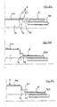
- la figure 1 est une coupe axiale partielle d'un appareillage pour la fabrication de pneumatique selon un premier mode de réalisation de l'invention,
- la figure 2 est une coupe partielle selon le plan P, du tambour de l'appareillage représenté sur la figure 1,
- la figure 3 est une coupe axiale partielle d'un appareillage selon une variante du premier mode de réalisation de l'invention,
- les figures 4A à 4J sont des représentations schématiques en coupe axiale partielle illustrant les différentes phases de la fabrication d'un pneumatique avec l'appareillage selon le premier mode de réalisation de l'invention,
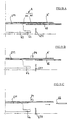
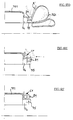
- la figure 5 est une coupe axiale partielle d'un appareillage pour la fabrication de pneumatique selon un deuxième mode de réalisation de l'invention,
- la figure 6 est une coupe axiale partielle d'un appareillage pour la fabrication de pneumatique selon un troisième mode de réalisation de l'invention,
- la figure 7 est une coupe axiale partielle d'un appareillage pour la fabrication de pneumatique selon un quatrième mode de réalisation de l'invention,
- la figure 8 est une coupe transversale de l'appareillage représenté sur la figure 5 selon la ligne VIII de ladite figure 5.
- la figure 9 est une coupe axiale partielle de l'appareillage illustré à la figure 6, pris dans une configuration différente,
- les figures 10A à 10G sont des représentations schématiques en coupe axiale partielle illustrant les différentes phases de la fabrication d'un pneumatique avec l'appareillage selon le deuxième mode de réalisation de l'invention.
- les figures 11A à 11G sont des représentations schématiques en coupe axiale partielle illustrant les différentes phases de la fabrication d'un pneumatique avec l'appareillage selon le troisième mode de réalisation de l'invention.
- les figures 12A à 12F sont des représentations schématiques en coupe axiale partielle illustrant les différentes phases de la fabrication d'un pneumatique avec l'appareillage selon le quatrième mode de réalisation de l'invention.
- FIG. 1 is a partial axial section of an apparatus for the manufacture of tires according to a first embodiment of the invention,
- FIG. 2 is a partial section along the plane P, of the drum of the apparatus shown in FIG. 1,
- FIG. 3 is a partial axial section of an apparatus according to a variant of the first embodiment of the invention,
- FIGS. 4A to 4J are schematic representations in partial axial section illustrating the different phases of the manufacture of a tire with the device according to the first embodiment of the invention,
- FIG. 5 is a partial axial section of an apparatus for the manufacture of tires according to a second embodiment of the invention,
- FIG. 6 is a partial axial section of an apparatus for manufacturing a tire according to a third embodiment of the invention,
- FIG. 7 is a partial axial section of an apparatus for manufacturing a tire according to a fourth embodiment of the invention,
- FIG. 8 is a cross section of the apparatus shown in FIG. 5 along line VIII of said FIG. 5.
- FIG. 9 is a partial axial section of the apparatus illustrated in FIG. 6, taken in a different configuration,
- FIGS. 10A to 10G are schematic representations in partial axial section illustrating the different phases of the manufacture of a tire with the device according to the second embodiment of the invention.
- FIGS. 11A to 11G are schematic representations in partial axial section illustrating the different phases of the manufacture of a tire with the device according to the third embodiment of the invention.
- FIGS. 12A to 12F are schematic representations in partial axial section illustrating the different phases of the manufacture of a tire with the device according to the fourth embodiment of the invention.
On propose ci-dessous différents types d'appareillage pour mettre en oeuvre l'invention. Dans l'ensemble de la description, on désignera par les mêmes références les éléments communs aux différentes variantes. A la lumière de la présente description, l'homme du métier pourra très facilement exécuter des appareillages symétriques ou non. Il suffit, pour exposer le concept de l'invention, d'expliquer en détails une seule moitiée axiale. On se limitera donc, dans ce qui suit, à la description de la partie de l'appareillage situé à droite du plan CP sur les différentes figures.Various types of apparatus are proposed below for implementing the invention. In the whole description, the common elements will be designated by the same references to the different variants. In the light of the present description, a person skilled in the art can very easily execute symmetrical or non-symmetrical equipment. It suffices to expose the concept of the invention, to explain in detail a single axial half. So we will limit ourselves, in the following, to the description of the part of the equipment located to the right of the CP plan on the different figures.
Comme évoqué par ailleurs, l'invention trouve également intérêt à être utilisé lorsque les bourrelets du pneumatique sont symétriques ou sont de diamètres différents. As mentioned elsewhere, the invention also finds advantage in being used when the the tire beads are symmetrical or have different diameters.
L'appareillage 1 comporte un tambour d'assemblage 10 monté sur un arbre 11, un dispositif
de retroussage 12, un dispositif (non représenté) d'amenée du complexe-tringle translatable
axialement vers et depuis le tambour 10, en laissant libre le volume à l'intérieur des
complexes-tringle. Le dispositif d'amenée du complexe-tringle peut prendre la forme par
exemple d'un anneau portant des doigts d'accrochage du complexe-tringle, ou d'un anneau
avec accrochage magnétique ou encore d'une couronne. L'appareillage comprend également
un dispositif comportant des doigts de rabattage 13, schématisés sur la figure 4B. Ce dernier
peut être intégré avec le dispositif d'amenée du complexe-tringle.The apparatus 1 comprises an
Le dispositif de retroussage 12 disposé axialement extérieurement au tambour 10, comporte
un support 122 monté à coulissement possible sur l'arbre 11. Le dispositif de retroussage 12
comprend aussi des membranes gonflables 121 portées par ledit support 122.On peut
également envisager d'utiliser, à la place des membranes, un dispositif de retroussage
comportant essentiellement des doigts de relevage. Un tel dispositif sera décrit plus
précisément dans la suite de la description en référence aux figures 5 et 6.The rolling-up
Le tambour d'assemblage 10 présente une surface de réception principale 101, généralement
cylindrique, et présente au moins un épaulement 102. La surface de réception principale 101
est constituée par des segments 103 juxtaposés circonférentiellement en position de travail du
tambour et montés, par l'intermédiaire de biellettes 105, à déplacement radial par rapport à
des supports 104, montés sur l'arbre 11. Les segments 103 permettent de rétracter radialement
le tambour 10 pour l'extraction (axialement) des carcasses réalisées sur ledit tambour. Ainsi
les segments 103 constituent un système de plusieurs segments adjacents
circonférentiellement, les faces latérales circonférentiellement de certains (B) étant
convergentes à l'intérieur du tambour (appelons-les par convention «les voûtes »), et les faces
latérales circonférentiellement des autres (A) étant convergentes à l'extérieur du tambour
(appelons-les par convention « les clés »). Cela permet de déplacer radialement vers l'intérieur
d'abord les voûtes, comme le montre la figure 2. Sur cette figure 2, sont représentés en traits
pleins les segments 103 en position de travail du tambour 10, les segments A et B successifs
constituant une surface continue cylindrique, et sont représentés en pointillés les mêmes
segments A et B en position rétractée, l'enveloppe constituée par les surfaces des segments B
étant de diamètre inférieur à celle constituée par les surfaces des segments A.The
Ce tambour 10 ne possède donc qu'une seule position radiale de travail utilisée pour
l'assemblage d'une carcasse de pneumatique, et une seule position rétractée pour l'extraction
de la carcasse. This
Le tambour 10 possède de plus une protubérence latérale 106 solidaire dudit tambour 10 et
fixe sur ce dernier, présentant une surface d'appui 107 généralement cylindrique, de diamètre
inférieur à celui de la surface de réception principale 101, de sorte que l'épaulement 102 reste
dégagé pour permettre d'effectuer la pose du complexe-tringle sur ledit épaulement par une
approche latérale.The
Notons que l'allure de la coupe radiale des segments 103, c'est à dire la forme de la surface
extérieure constituée par la surface de réception principale 101 prolongée par les épaulements
102 peut varier quelque peu. Par exemple, elle peut être moins carrée aux épaulements,
comme cela apparaít par exemple dans le brevet US 1 911 594. C'est à dire que les
épaulements peuvent être quelque peu inclinés par rapport à la direction radiale, sans présenter
de portion comprise dans un plan perpendiculaire à l'axe. Vus en section radiale, les
épaulements sont alors assez penchés, tout en gardant des raccordements arrondis.
Comme le montrent les figures 1 et 3, l'appareillage 1 comporte également une couronne
latérale 14 (14') coaxiale audit tambour 10, présentant une surface d'appui 141 (141')
généralement cylindrique, de diamètre inférieur à celui de la protubérence latérale 106. Cette
couronne latérale 14 est (14') montée sur l'arbre 11 et est mobile axialement par rapport au
tambour 10, comme expliqué ci-après.Note that the shape of the radial section of the
Selon la variante représentée à la figure 1, la couronne latérale 14 est montée sur le dispositif
de retroussage 12 axialement intérieurement par rapport au centre de l'appareillage 1, et est
solidaire en translation axiale dudit dispositif Le diamètre de la surface d'appui 141 de la
couronne latérale 14 est inférieur au diamètre intérieur des segments 103 dans leur position de
travail afin de permettre son escamotage sous lesdits segments. Le déplacement axial du
dispositif de retroussage 12 permet, en effet, d'actionner la couronne latérale 14 entre une
position avancée transversalement, représentée sur la figure 1, où cette dernière dépasse
axialement du tambour 10 et une position escamotée où la couronne latérale 14 est masquée
par le tambour 10.According to the variant shown in Figure 1, the
Selon une deuxième variante de réalisation de l'appareillage représentée sur la figure 3, la
couronne latérale 14' est montée sur le tambour d'assemblage 10 radialement sous la
protubérence latérale 106, et à translation axiale possible par rapport aux segments 103 entre
une position avancée où elle dépasse axialement par rapport à la protubérence latérale 106 au
dessus du dispositif de retroussage 12 et une position escamotée sous la protubérence latérale
106. Cette disposition permet de moduler la longueur de la membrane utilisée effectivement
pour un retroussage, la couronne latérale 14' étant susceptible, lors du mouvement de
glissement axial, de recouvrir partiellement le dispositif de retroussage. En effet, lors d'une
expansion des membranes de retroussage 121, la couronne latérale 14' étant en position
avancée, les membranes n'agissent pas sur les produits posés sur la protubérence latérale 106
comme on le verra plus en détails dans la description du procédé de fabrication.According to a second alternative embodiment of the apparatus shown in FIG. 3, the
Notons que si l'on souhaite fabriquer un pneumatique ayant deux bourrelets de diamètres différents avec pour chaque bourrelet un retournement de l'armature de carcasse entre la tringle et l'armature elle-même, on peut prévoir un appareillage asymétrique par rapport au plan P de sorte que les couronnes, et respectivement les protubérences latérales, disposées de part et d'autre du plan P présentent des surfaces d'appui de diamètres différents, en respectant bien entendu pour chaque côté dudit plan, l'agencement relatif de la couronne et de la protubérence latérale décrit précédemment.Note that if one wishes to manufacture a tire having two beads of diameters different with for each bead a reversal of the carcass reinforcement between the rod and the frame itself, one can provide an asymmetrical fitting with respect to the plane P so that the crowns, and respectively the lateral protuberances, arranged in on either side of plane P have bearing surfaces of different diameters, respecting of course for each side of said plane, the relative arrangement of the crown and the lateral protuberance described above.
Les différents moyens mis en oeuvre pour commander la rotation autour de l'axe de rotation
des différents éléments de l'appareillage ne requièrent pas d'explications détaillées. Signalons
simplement qu'il convient de commander en rotation non seulement le tambour 10, mais aussi
de préférence le dispositif de retroussage 12 car il sert lui aussi de surface de pose de
différents produits constitutifs du pneumatique à fabriquer. La commande en rotation du
dispositif de retroussage 12 peut provenir directement de l'arbre 11, ou bien le dispositif de
retroussage peut être embrayé à la demande sur le tambour 10, par exemple par une chambre
tubulaire gonflable 109 insérée sur la surface d'appui 141, du côté axialement intérieur de
celle-ci. L'embrayage du dispositif de retroussage 12 se fait alors par gonflage.The different means used to control the rotation around the axis of rotation
of the various elements of the apparatus do not require detailed explanations. Let's point out
simply that it is necessary to control in rotation not only the
On décrira dans ce qui suit, pour ce premier mode de réalisation de l'invention, en référence aux figures 4A à 4J, le procédé de fabrication d'un pneumatique à armature de carcasse radiale de tourisme comprenant une armature de carcasse, au moins une tringle de renforcement dans chacun des bourrelets dudit pneumatique, et plus particulièrement la réalisation d'un de ces bourrelets dans lequel l'armature de carcasse forme un retournement disposé entre la tringle et l'armature de carcasse elle-même.We will describe in the following, for this first embodiment of the invention, with reference in FIGS. 4A to 4J, the method of manufacturing a tire with a carcass reinforcement radial of tourism comprising a carcass reinforcement, at least one rod of reinforcement in each of the beads of said tire, and more particularly the production of one of these beads in which the carcass reinforcement forms a reversal disposed between the rod and the carcass reinforcement itself.
Bien entendu, le procédé de fabrication permet indifféremment la réalisation d'un pneumatique avec un seul bourrelet du type décrit ci-dessus ou deux bourrelets de ce type, et l'exemple choisi d'un pneumatique de tourisme à carcasse radiale ne saurait limiter l'invention à ce seul type de pneumatique.Of course, the manufacturing process indifferently allows the realization of a pneumatic with a single bead of the type described above or two beads of this type, and the example chosen for a passenger car tire with a radial carcass cannot limit the invention only to this type of tire.
Les figures 4A à 4J illustrent schématiquement ce procédé dans le premier mode de réalisation de l'invention selon la première variante de l'appareillage 1 représentée sur la figure 1, la mise en oeuvre du procédé avec la deuxième variante de l'appareillage 1 se déduisant aisément de celui-ci. FIGS. 4A to 4J schematically illustrate this method in the first embodiment of the invention according to the first variant of the apparatus 1 shown in Figure 1, the setting implementing the method with the second variant of the apparatus 1 easily deduced from this one.
Selon la figure 4A, le tambour 10 étant en position de travail et la couronne latérale 14 en
position déployée, c'est à dire écartée axialement, on dépose sur la surface de réception
principale 101 une nappe de caoutchouc appelée «nappe intérieure» NI, puis une nappe de
câbles textiles, appelée «nappe carcasse» NC. L'ensemble de ces nappes NI et NC constitue
ce que l'on appelle ici collectivement «armature de carcasse» A. L'extrémité A' de
l'armature de carcasse A dépasse axialement de la surface de réception principale 101 et
surplombe la protubérence latérale 106et la couronne latérale 14, ainsi qu'une partie des
membranes de retroussage.According to FIG. 4A, the
On rabat ensuite l'extrémité A' de l'armature de carcasse A radialement vers l'intérieur, sur
respectivement la surface d'appui 107 de la protubérence latérale 106, la surface d'appui 141
de la couronne latérale 14 et partiellement sur les membranes 121 à l'aide des doigts de
rabattage 13, comme le montre la figure 4B.The end A ′ of the carcass reinforcement A is then folded radially inwards, on
respectively the bearing
Selon une variante, on peut également poser la nappe de carcasse en légère tension. La propension au retrait qui en résulte provoque spontanément une rétrainte diamétrale des extrémités A', que l'on peut compléter par un rabattage comme décrit ci-dessus ou un rouletage, pour appliquer correctement ladite armature de carcasse sur les surfaces de réception et d'appui.Alternatively, the carcass ply can also be laid in slight tension. The propensity for the resulting shrinkage spontaneously causes diametrical retension of ends A ', which can be completed by a folding down as described above or a rolling, to correctly apply said carcass reinforcement to the surfaces of reception and support.
On dépose ensuite, comme représenté sur la figure 4C, un profilé de mélange caoutchouteux
P1 sur la zone de l'extrémité A' de l'armature de carcasse A disposée sur la surface d'appui
141 de la couronne latérale 14. Ce profilé P1 possède dans l'exemple décrit une section avant
la forme d'un quadrilatère mais on peut envisager d'autres formes de section. De façon
avantageuse, on choisit pour réaliser le profilé P1 un mélange caoutchouteux ayant à une
viscosité Mooney ML (1+4) à 100°C mesurée selon la norme ASTM:D-1646, supérieure ou
égale à 70, afin que le profilé P1 soit suffisamment dur et la rotation de l'extrémité A' autour
dudit profilé P1 s'en trouve facilitée.Next, as shown in FIG. 4C, a rubber mix profile is deposited.
P1 on the area of the end A ′ of the carcass reinforcement A disposed on the
On gonfle alors les membranes de retroussage qui relèvent radialement l'extrémité A' situé
axialement extérieurement à la couronne latérale 14 et donc au profilé P1. Ainsi la zone de
l'extrémité A' soulevée fait une rotation autour du profilé P1 de sorte à ce que cette dernière
est orientée sensiblement radialement, comme le montrent les figures 4D et 4E. Notons au
passage qu'au moins la portion des membranes 121 au contact avec l'armature de carcasse A
est choisie et/ou traitée pour que l'armature de carcasse A ne colle pas sur ladite portion (par
exemple parce que sa surface est recouverte d'un tissu textile approprié). The roll-up membranes are then inflated, which raise the end A 'situated radially.
axially externally to the
Conformément à la figure 4F, on dégonfle ensuite les membranes de retroussage 121,
l'extrémité A' soulevée se maintenant dans sa position orientée sensiblement radialement, et
on rapproche axialement, grâce au dispositif d'amenée de complexe-tringle, un complexe-tringle
CT. Le complexe-tringle CT est constitué dans cet exemple par une tringle T de section
carrée, faite de fils ou de câbles, surmontée radialement par un profilé de mélange
caoutchouteux P2.In accordance with FIG. 4F, the roll-up
On rapproche axialement le complexe-tringle CT jusqu'à l'appui sur ce dernier de l'extrémité
A'. On continue alors le rapprochement axial du complexe-tringle CT entraínant ainsi avec lui
l'extrémité A' qui est retournée, et passant au dessus du profilé P1 recouvert par une partie de
l'extrémité A'. Le complexe-tringle CT est ainsi rapproché jusqu'à son contact avec
l'épaulement 102 par l'intermédiaire de l'extrémité A' retournée, qui se retrouve ainsi entre la
tringle T et l'armature de carcasse A, comme on le voit sur la figure 4G.The CT rod complex is brought axially until it is pressed against the end
AT'. We then continue the axial approximation of the rod complex CT thus entraining with it
the end A 'which is turned over, and passing above the section P1 covered by a part of
the end A '. The CT rod complex is thus brought together until it comes into contact with
the
Le dépôt du complexe-tringle CT sur le retournement de l'extrémité A' de l'armature de
carcasse A est ainsi effectué à l'aplomb de la deuxième surface d'appui cylindrique 107
coaxiale, disposée entre la surface de réception principale 101 et la première surface d'appui
141 (ou 141'), le diamètre de la surface de réception principale 101 étant supérieur à celui de
la deuxième surface d'appui, lui-même supérieur au diamètre de la première surface d'appui
(voir aussi 741, 711, 751 ci-dessous).The deposit of the rod rod complex CT on the inversion of the end A 'of the reinforcement
carcass A is thus carried out directly above the second
La couronne latérale 14 est ensuite déplacée axialement vers le centre (plan CP), ce qui
escamote sous la protubérence latérale 106 la première surface d'appui 141 (141' dans la
variante illustrée à la figure 3), de sorte que le profilé P1 entouré de l'armature de carcasse A
est désormais juste par dessus les membranes de retroussage 121 (figure 4H).The
On gonfle une nouvelle fois les membranes de retroussage 121 qui réalisent cette fois un
basculement du profilé P1 (figure 4I) contre le complexe-tringle, ou au moins qui le relève
radialement quelque peu par rapport au complexe-tringle CT et aident à le plaquer
latéralement contre le complexe-tringle CT.The roll-up
Cette étape étant réalisée, on dégonfle les membranes de retroussage 121. Le bourrelet cru de la carcasse garde sa forme (figure 4J).This step having been carried out, the roll-up membranes are deflated 121. The raw bead of the carcass retains its shape (Figure 4J).
On pose ensuite les autres produits constitutifs du pneumatique et on procède à la vulcanisation de ce dernier. L'invention ne concerne pas cette partie de la fabrication. De nombreuses méthodes sont disponibles à l'homme du métier, c'est pourquoi il est inutile d'aborder cet aspect de la fabrication dans le contexte de la présente invention. The other constituent products of the tire are then placed and the vulcanization of the latter. The invention does not relate to this part of the manufacturing. Of many methods are available to those skilled in the art, which is why it is unnecessary to address this aspect of manufacturing in the context of the present invention.
Dans ce qui suit on utilisera des références identiques pour les constituants communs d'une carcasse de pneumatique réalisée par l'un quelconque des appareillages conformes à l'invention.In what follows, identical references will be used for the common constituents of a tire casing produced by any of the equipment conforming to the invention.
On peut également envisager de réaliser le procédé selon l'invention avec des appareillages comportant des tambours expansibles radialement par rapport à une première position de travail et possédant des épaulements afin de permettre l'utilisation de complexes-tringle déposés sur lesdits épaulements.It is also possible to envisage carrying out the method according to the invention with apparatus comprising radially expandable drums relative to a first position of working and having shoulders to allow the use of rod complexes deposited on said shoulders.
De tels appareillages sont représentés sur les figures 5, 6 et 7. On désignera respectivement ces appareillages par des références débutant par 5, 6 et 7.Such devices are shown in Figures 5, 6 and 7. We will respectively denote these devices with references starting with 5, 6 and 7.
Les appareillages 5, 6, 7 comprennent respectivement un tambour d'assemblage 50, 60, 70,
expansible radialement, comprend un corps central 51, 61, 71 monté sur un arbre 52, 62, 72,
présentant une surface de réception 511, 611, 711 des produits à assembler et des épaulements
514, 614, 714.The
Ces appareillages 5, 6, 7 comprennent également un système d'amenée des complexes-tringle,
non représenté, translatable axialement vers le tambour 50, 60, 70 en laissant libre le diamètre
intérieur des complexes-tringle comme décrit pour l'exemple précédent. Mais, contrairement
à l'exemple précédent, les appareillages 5, 6, 7 sont ici utilisés sans doigts de rabattage,
comme on le comprendra à la lecture du procédé de fabrication mettant en oeuvre ces
appareillages.These
Les tambours 50, 60, 70 décrits dans cet exemple de réalisation de l'invention étant
symétriques par rapport à un plan P représenté sur les figures 5, 6, 7, on ne décrira dans la
suite de la description que les demi-tambours situés à droite du plan P sur lesdites figures. Le
choix des tambours décrits ici ne limite pas la portée de l'invention à des tambours
symétriques.The
Le corps central 51 (61, 71) comprend un demi-corps 512 (612, 712) déplaçable axialement autour de l'arbre 52 (62, 72) afin de régler l'écartement des tringles du pneumatique à réaliser, et une couronne centrale 513 (613, 713) fixe axialement par rapport à l'arbre 52 (62, 72).The central body 51 (61, 71) comprises an axially displaceable half-body 512 (612, 712) around the shaft 52 (62, 72) in order to adjust the spacing of the bead wires of the tire to be produced, and a central ring 513 (613, 713) fixed axially relative to the shaft 52 (62, 72).
Le demi-corps 512 (612, 712) et la couronne centrale 513 (613, 713) sont constitués par une pluralité de segments latéraux 522 (622, 722) et centraux 523 (623, 723) respectivement en vis-a-vis. Les segments latéraux 522 (622, 722) sont juxtaposés circonférentiellement autour de l'arbre 52 (62, 72) et, de même, les segments centraux 523 (623, 723) sont juxtaposés circonférentiellement autour de l'arbre 52 (62, 72). Pour assurer la liaison des différents éléments du corps 51 (61, 71), chaque segment latéral 522 (622, 722) est guidé par rapport au segment central 523 (623, 723) en vis-à-vis au moyen d'une tige 515 (615, 715) dont une extrémité traverse le segment central 523 (623, 723) et dont l'autre extrémité est montée à coulissement dans un alésage 516 (616, 716) porté par le segment latéral 522 (622, 722) en vis-à-vis.The half-body 512 (612, 712) and the central crown 513 (613, 713) are constituted by a plurality of lateral segments 522 (622, 722) and central 523 (623, 723) respectively in vis-a-vis. The lateral segments 522 (622, 722) are juxtaposed circumferentially around of the shaft 52 (62, 72) and, similarly, the central segments 523 (623, 723) are juxtaposed circumferentially around the shaft 52 (62, 72). To ensure the connection of the different body elements 51 (61, 71), each lateral segment 522 (622, 722) is guided relative to the central segment 523 (623, 723) opposite by means of a rod 515 (615, 715), one of which end crosses the central segment 523 (623, 723) and the other end of which is mounted at sliding in a bore 516 (616, 716) carried by the lateral segment 522 (622, 722) in vis-a-vis.
Afin de permettre au tambour 50 (60, 70) d'atteindre sa position expansée, les segments 522 (622, 722) sont mobiles radialement sous l'action d'une chambre d'expansion gonflable 517 (617, 717) disposée sous lesdits segments latéraux 522 (622, 722). Les segments latéraux 522 (622, 722) entraínent dans leur mouvement radial les segments centraux 523 (623, 723) de la couronne centrale 513 (613, 713), qui sont solidaires en déplacement radial des segments latéraux 522 (622, 722) par l'intermédiaire des tiges 515 (615, 715).In order to allow the drum 50 (60, 70) to reach its expanded position, the segments 522 (622, 722) are radially movable under the action of an inflatable expansion chamber 517 (617, 717) disposed under said lateral segments 522 (622, 722). Lateral segments 522 (622, 722) entrain in their radial movement the central segments 523 (623, 723) of the central crown 513 (613, 713), which are integral in radial displacement with the segments lateral 522 (622, 722) via the rods 515 (615, 715).
Des plaquettes 518 (618, 718) sont fixées par des vis sur les segments 523 (623, 723) de la couronne centrale 513 (613, 713). Ces plaquettes 518 (618, 718) recouvrent au moins partiellement les segments 522 (622, 722) du demi-corps 512 (612, 712) afin d'assurer une continuité entre la couronne centrale 513 (613, 713) et ledit demi-corps 512 (612, 712) pour les produits à assembler quelle que soit la position axiale du demi-corps 512 (612, 712). La couronne centrale 513 (613, 713) permet, de plus, d'assurer un maintien axial des plaquettes 518 (618, 718) lors de l'expansion radial du tambour 50 (60, 70). Bien entendu, on peut envisager d'autres éléments que les chambres d'expansion afin de réaliser une expansion radiale du tambour.Platelets 518 (618, 718) are fixed by screws on the segments 523 (623, 723) of the central crown 513 (613, 713). These plates 518 (618, 718) cover at least partially the segments 522 (622, 722) of the half-body 512 (612, 712) in order to ensure a continuity between the central crown 513 (613, 713) and said half-body 512 (612, 712) for the products to be assembled regardless of the axial position of the half-body 512 (612, 712). The central crown 513 (613, 713) also makes it possible to ensure axial retention of the inserts 518 (618, 718) during the radial expansion of the drum 50 (60, 70). Of course, we can consider elements other than expansion chambers in order to achieve expansion radial of the drum.
La surface de réception 511 (611, 711) des produits à assembler est ainsi constituée par l'ensemble des surfaces extérieures des plaquettes 518 (618, 718) et des zones des segments 522 (622, 722) non recouvertes par lesdites plaquettes 518 (618, 718).The receiving surface 511 (611, 711) of the products to be assembled is thus constituted by all the external surfaces of the plates 518 (618, 718) and of the zones of the segments 522 (622, 722) not covered by said plates 518 (618, 718).
On décrira plus précisément dans ce qui suit dans un premier temps les éléments communs
aux appareillages 5 et 6 en référence aux figures 5 et 6 puis leurs caractéristiques spécifiques,
et dans une deuxième temps l'appareillage 7 en référence à la figure 7.We will describe more precisely in the following first the common elements
to apparatuses 5 and 6 with reference to FIGS. 5 and 6 then their specific characteristics,
and in a second step the
Le tambour 50 (60) comporte une protubérence latérale 54 (64) expansible radialement, solidaire du corps 51 (61) et présentant une surface d'appui 541 (641) des produits à assembler. La protubérence latérale 54 (64) est juxtaposée coaxialement à l'épaulement 514 (614) du corps 51 (61) et forme une surface d'appui 541(641) de diamètre inférieur à celui de ladite surface de réception principale 511 (611) . Une réalisation possible de la protubérence latérale 54 (64) consiste à la former sous forme de segments venant respectivement en prolongement des segments 522 (622) du demi-corps 512 (612). On peut également, sans sortir du cadre de l'invention, envisager que la protubérence latérale 54 (64) soit un élément rapporté par rapport au corps 51 (61).The drum 50 (60) has a radially expandable lateral protuberance 54 (64), integral with the body 51 (61) and having a bearing surface 541 (641) of the products to to assemble. The lateral protuberance 54 (64) is juxtaposed coaxially with the shoulder 514 (614) of the body 51 (61) and forms a bearing surface 541 (641) of diameter smaller than that of said main receiving surface 511 (611). A possible realization of the protuberance lateral 54 (64) consists in forming it in the form of segments respectively coming in extension of the segments 522 (622) of the half-body 512 (612). We can also, without depart from the scope of the invention, consider that the lateral protuberance 54 (64) is an element reported relative to body 51 (61).
L'appareillage 5 (6) comporte un dispositif de retroussage 55 (65) monté sur l'arbre 52 (62) axialement extérieurement à la protubérence latérale 54 (64). Ce dispositif de retroussage 55 (65) peut être constitué, comme dans l'exemple de l'appareillage 1, par des membranes de retroussage. On a choisi pour cet exemple un dispositif de retroussage 55 (65) comprenant des doigts de relevage; on entend par le terme « doigt » un profilé de faible section.The apparatus 5 (6) comprises a rolling-up device 55 (65) mounted on the shaft 52 (62) axially externally to the lateral protuberance 54 (64). This roll-up device 55 (65) can be constituted, as in the example of the apparatus 1, by membranes of roll up. For this example, a roll-up device 55 (65) has been chosen comprising lifting fingers; the term “finger” is understood to mean a profile of small cross section.
Sur les figures 5 et 6, le dispositif de retroussage 55 (65) est indépendant du tambour 50 (60) et peut être translaté axialement, cependant on peut également envisager que ce dispositif soit solidaire du tambour 50 (60) auquel cas il est intéressant d'utiliser les segments 522 (622) du demi-corps (512, 612) comme supports respectifs des doigts de relevage.In FIGS. 5 and 6, the roll-up device 55 (65) is independent of the drum 50 (60) and can be axially translated, however it can also be envisaged that this device is integral with the drum 50 (60) in which case it is advantageous to use the segments 522 (622) of the half-body (512, 612) as respective supports for the lifting fingers.
Le dispositif de retroussage 55 (65) comporte donc une pluralité de doigts de relevage 551 (651), de section rectangulaire (si vus radialement), répartis circulairement autour de l'arbre 52 (62) et s'étendant dans des directions radiales.The roll-up device 55 (65) therefore comprises a plurality of lifting fingers 551 (651), of rectangular section (if seen radially), distributed circularly around the shaft 52 (62) and extending in radial directions.
Ces doigts de relevage 551 (651) sont disposés axialement extérieurement par rapport au centre du tambour 50 (60), à une faible distance de l'extrémité libre de la protubérence latérale 54 (64), et présentent respectivement une surface de contact 552 (652) des produits à assembler. Les doigts de relevage 551 (651) sont montés à déplacement radial possible respectivement sur un support cylindrique 553 (653) monté à translation axiale sur l'arbre 52 (62) par l'intermédiaire de vérins 554 (654).These lifting fingers 551 (651) are arranged axially outwardly relative to the center of drum 50 (60), a short distance from the free end of the lateral protuberance 54 (64), and respectively have a contact surface 552 (652) of the products to to assemble. The lifting fingers 551 (651) are mounted with possible radial displacement respectively on a cylindrical support 553 (653) mounted in axial translation on the shaft 52 (62) by means of cylinders 554 (654).
En effet, l'extrémité radialement intérieure au corps 51 de chaque doigt de relevage 551 (651)
porte un prolongement 558 (658) axial sur lequel est fixé, par l'intermédiaire de vis, le vérin
554 (654) correspondant qui coulisse radialement dans un logement 555 (655) portée par le
support cylindrique 553 (653).Indeed, the end radially inside the
Ainsi, les doigts de relevage 551 (651) sont déployables radialement vers l'extérieur du tambour 50 (60) à partir d'une position de repos vers une position déployée. Et, afin d'assurer le retour en position de repos des doigts de relevage 551 (651), une ceinture élastique de rappel 559 (659) entoure l'ensemble des prolongements axiaux 558 (658).Thus, the lifting fingers 551 (651) can be deployed radially outwards from the drum 50 (60) from a rest position to a deployed position. And, in order to ensure the return of the lifting fingers 551 (651) to the rest position, an elastic belt of recall 559 (659) surrounds all of the axial extensions 558 (658).
Ces doigts de relevage 551 (651) offrent ainsi aux produits à assembler une pluralité de surfaces de contact 552 (652) discontinues et réparties circonférentiellement. These lifting fingers 551 (651) thus offer the products to be assembled a plurality of contact surfaces 552 (652) discontinuous and distributed circumferentially.
Avantageusement, les extrémités libres des doigts de relevage 551 (651), c'est-à-dire radialement extérieures au tambour 50 (60), sont constituées par un galet 557 (657) monté libre en rotation autour d'un axe et qui porte ainsi la surface de contact 552 (652). Ce galet 557 (657) permet d'éviter de créer des tensions au niveau des produits soulevés lors du déploiement des doigts de relevage 551 (651) en assurant, dans cette phase, un contact « roulant » entre les doigts et les produits.Advantageously, the free ends of the lifting fingers 551 (651), that is to say radially external to the drum 50 (60), are constituted by a roller 557 (657) mounted free in rotation about an axis and which thus carries the contact surface 552 (652). This pebble 557 (657) avoids creating tension in the products raised during deployment of the lifting fingers 551 (651) ensuring, in this phase, a contact "Rolling" between fingers and products.
Selon la figure 5, le tambour 50 porte des moyens d'expansion 57, qui comprennent
notamment les chambres d'expansion 517, vers deux positions expansées distinctes et qui
permettent d'atteindre ses deux positions successivement. De la sorte, le tambour peut prendre
trois positions stables distinctes, caractérisées par trois développements circonférentiels
différents que présenterait une corde enroulée autour de la surface de réception principale.According to Figure 5, the
Différentes solutions peuvent être envisagées afin de réaliser ces deux expansions successives
du tambour 50. Dans l'exemple choisi, les moyens d'expansion 57 comprennent un anneau
572 de commande monté sur un anneau support 573, les deux anneaux étant montés sur
l'arbre 52 et disposés axialement extérieurement au corps 51 à proximité de l'extrémité libre
de la protubérence latérale 54. Aux fins d'une plus grande compacité, l'anneau support 573
porte un épaulement cylindrique intérieur 573' qui coopère avec l'anneau de commande 572.Different solutions can be envisaged in order to achieve these two successive expansions
of the
L'anneau de commande 572 est monté de façon rotative par rapport au corps 51 du tambour
50, l'anneau support 573 étant solidaire en rotation dudit corps 51.The
Comme le montrent les figures 5 et 8, la protubérence latérale 54 porte au moins un pion
d'engagement 542 dans une came 574 portée par l'anneau de commande 572 et,
simultanément, dans une lumière 575 orientée dans une direction radiale et portée par
l'anneau support 573. Dans l'exemple choisi, chacun des segments constituant la protubérence
latérale 54 porte un pion d'engagement dans une came et une lumière correspondantes.As shown in FIGS. 5 and 8, the
La position expansée accessible au tambour 51 est tributaire de la position angulaire de
l'anneau de commande 572. En effet, en fonction de la rotation de l'anneau de commande 572
et donc de sa position angulaire et de celle des cames 574, les pions d'engagement 542 ont une
plage de positionnement radial différente, ce qui limite donc l'expansion radiale du tambour
50, les lumières 575 assurant le guidage radialement des pions d'engagement 542.The expanded position accessible to the
La rotation angulaire de l'anneau de commande 572 est obtenue par l'utilisation d'un vérin
d'actionnement non représenté. Selon la figure 8, chaque came 574 présente une forme
ressemblant à un Z, les positions possibles du pion d'engagement 542 correspondant dans
chaque côté du Z correspondant aux trois positions du tambour 50, c'est-à-dire une position
rétractée, une position expansée intermédiaire et une position expansée maximale.The angular rotation of the
Sans sortir du cadre de l'invention, on peut envisager des éléments autres que les chambres
d'expansion 517 afin de réaliser une expansion radiale du tambour 50. Le système
d'assujettissement du positionnement radial du tambour 50 au positionnement circonférentiel
de l'anneau de commande 572 n'est pas lié au choix de chambres d'expansion 517.Without departing from the scope of the invention, it is possible to envisage elements other than the
On peut envisager d'utiliser un seul ensemble anneau de commande - anneau support. Cependant, on préférera en utiliser deux, un à chaque extrémité du corps du tambour afin d'assurer un bon synchronisme d'expansion entre les deux extrémités du tambour.We can consider using a single set of control ring - support ring. However, we prefer to use two, one at each end of the drum body in order to ensure good expansion synchronism between the two ends of the drum.
Comme on le comprendra mieux à la lecture du fonctionnement de cet appareillage 5, le dispositif de retroussage 55 est réalisé de sorte que les surfaces de contact 552 des doigts de relevage 551 constituent sensiblement une surface cylindrique coaxiale à l'arbre 52 dont le diamètre est :
- en position de repos desdits doigts, inférieur ou égal au diamètre de la
surface d'appui 541 de la protubérence latérale 54 dans la position expansée intermédiaire du tambour 50, - et en position déployée, supérieur au diamètre de la
surface d'appui 541 de la protubérence latérale 54 dans la position expansée intermédiaire du tambour 50.
- in the rest position of said fingers, less than or equal to the diameter of the bearing
surface 541 of thelateral protuberance 54 in the intermediate expanded position of thedrum 50, - and in the deployed position, greater than the diameter of the bearing
surface 541 of thelateral protuberance 54 in the intermediate expanded position of thedrum 50.
Les fleures 10A à 10G illustrent schématiquement ce procédé dans le deuxième mode de réalisation de l'invention utilisant l'appareillage 5.Flowers 10A to 10G schematically illustrate this process in the second mode of realization of the invention using the apparatus 5.
Selon la figure 10A, le tambour 50 étant en position contractée, on dépose sur la surface de
réception 511 les nappes NI et NC constituant l'armature de carcasse A. L'extrémité A' de
l'armature de carcasse dépasse axialement de la surface de réception 511 et couvre la
protubérence latérale 54 ainsi que les doigts de relevage 551 du dispositif de retroussage 55.According to FIG. 10A, the
Selon la figure 10B, on rabat ensuite l'extrémité A' de l'armature de carcasse A sur
respectivement la surface d'appui 541 de la protubérence latérale 541 en réalisant une
première expansion du tambour 50 grâce aux anneaux de commande 572 et support 573.
L'expansion du tambour 50 en position intermédiaire permet de plaquer l'extrémité A' sur la
surface d'appui 541 et celle constituée par les surfaces de contact 557 du dispositif de
retroussage 55. According to FIG. 10B, the end A ′ of the carcass reinforcement A is then folded over
respectively the bearing
On dépose ensuite, comme représenté sur la figure 10C, le profilé de mélange caoutchouteux
P1 sur la zone de l'extrémité A' de l'armature de carcasse A disposée sur la surface d'appui
541 de la protubérence latérale 54.Next, as shown in FIG. 10C, the rubber mix profile is deposited
P1 on the area of the end A ′ of the carcass reinforcement A disposed on the
On déploie alors radialement les doigts de relevage 551 jusqu'à la position déployée dans
laquelle les surfaces de contact 557 constituent sensiblement une surface cylindrique de
diamètre supérieur au diamètre de la surface d'appui 541 de sorte que les doigts 551 relèvent
radialement l'extrémité A' située axialement extérieurement à la protubérence latérale 54 et
donc au profilé P1. Ainsi la zone de l'extrémité A' soulevée fait une rotation autour du profilé
P1 de sorte à ce que cette dernière est orientée sensiblement radialement, comme le montre la
figure 10D.The lifting
Conformément à la figure 10E, les doigts de relevage 551 étant toujours en position déployée,
on rapproche axialement, grâce au dispositif d'amenée de complexe-tringle, le complexe-tringle
CT jusqu'à l'appui sur ce dernier de l'extrémité A'.In accordance with FIG. 10E, the lifting
On peut rappeler en position de repos les doigts de relevage 551 grâce à la ceinture élastique
559 et on continue le rapprochement axial du complexe-tringle CT entraínant ainsi avec lui
l'extrémité A' qui est retournée, et passant au dessus du profilé P1 recouvert par une partie de
l'extrémité A', comme on le voit sur la figure 10F. On notera cependant que l'on peut
également rappeler les doigts 551 avant l'appui de l'extrémité A' sur le complexe-tringle.The lifting
On actionne alors, simultanément à l'avance du complexe-tringle CT, l'anneau de commande
572 afin d'amener le tambour 50 dans sa position expansée maximale. L'expansion radiale de
la surface d'appui 541 qui en résulte relève radialement le profilé P1 par rapport au
complexe-tringle CT (voir figure 10G).The control ring is then actuated simultaneously in advance of the
Quant à l'appareillage 6, il comporte en plus des éléments déjà décrits (à savoir le tambour 60,
l'arbre 62, la protubérence latérale 64 solidaire du tambour 60 et le dispositif de retroussage
65) une virole 66 mobile axialement, par exemple montée sur l'arbre 62.As for the apparatus 6, it comprises in addition to the elements already described (namely the
Cette virole 66 possède un diamètre sensiblement identique à celui de la surface de réception
611 et est montée, de façon translatable par rapport à l'arbre 62, entre une position escamotée
et une position de recouvrement de la surface 641 de la protubérence latérale 64 dans laquelle
la virole 66 recouvre ladite surface 541 comme le montre la figure 6. Comme on le verra plus
précisément dans la description du fonctionnement de l'appareillage 6, la présence de la virole
66 assure un support ferme pour la pose d'un profilé de mélange caoutchouteux. This
La virole 66 est portée par un support 67 monté sur l'arbre 62. Le support 67 comporte un
anneau extérieur 671, concentrique à l'arbre 62 et qui recouvre la virole 66 dans la position
escamotée de cette dernière. Le diamètre de l'anneau extérieur 671 est choisi le plus proche
possible de celui de la virole 66, afin de permettre le passage du complexe-tringle au-dessus
de l'anneau extérieur. Le support 67 est monté déplaçable axialement sur l'arbre 62 afin
notamment, de faciliter des opérations de démontage ou d'accès au tambour 60.The
A son extrémité latérale orientée à l'opposé du tambour 61, le support 67 porte une chambre
annulaire 672 concentrique à l'arbre 62 à l'intérieur de laquelle coulisse axialement un piston
673 d'actionnement de la virole 66, relié à cette dernière par une bielle 674, montée rotative
autour de l'axe 674A, lui-même monté sur le support 67. La liaison de la bielle 674 avec la
virole 66 est réalisée par le montage d'un axe solidaire d'un palier 675, ledit axe pénétrant
dans un orifice allongé 674B aménagé à une des extrémités de la bielle 674. Le palier 675 est
par ailleurs coulissant par rapport à l'anneau extérieur 671, ce qui assure le guidage en
translation de la virole 66. L'autre exprémité de la bille 674 coopère avec le piston 673 qui
assure la commande du basculement de la bielle (par exemple par un galet engagé dans une
came solidaire du piston 673). Le lecteur est invité à consulter la figure 9 qui montre, dans sa
partie supérieure, la virole dans la même position que celle occupée à la figure 6, et qui
montre, dans sa partie inférieure, la bielle 674 basculée et la virole 66 escamotée sous
l'anneau extérieur 671.At its lateral end oriented opposite the
Le tambour 60 ne possède dans cet exemple que deux positions de travail : une position
retractée correspondant à la position dégonflée de la chambre d'expansion vessies de gonflage
617 et une position expansée à la position gonflée de la chambre d'expansion 617. Notons
cependant que dans une réalisation asymétrique de l'appareillage aux fins de réaliser un
pneumatique avec deux bourrelets de diamètres différents et par conséquent un appareillage
avec deux couronnes solidaires du tambour de diamètres différents, il est utile de prévoir sur
le tambour un dispositif d'expansion permettant d'atteindre deux positions d'expansion
successives permettant de gérer lors de la fabrication cette différence de diamètre.The
Dans cette réalisation on préfère utiliser un dispositif de retroussage utilisant des doigts de
relevage 651, décrits précédemment, aux membranes de retroussage. En effet, comme le
montra plus en détails la description du procédé, le dispositif de retroussage doit être capable
d'un déplacement radial important, ce qui est plus aisément réalisable avec des doigts de
relevage. In this embodiment, it is preferable to use a roll-up
Ce dispositif de retroussage 65 est réalisé de sorte que les surfaces de contact 652 des doigts de relevage 651 constituent sensiblement une surface cylindrique coaxiale à l'arbre 62 dont le diamètre est :
- en position de repos desdits doigts, inférieur à celui de surface de réception 611 en position contractée du tambour 61 afin de permettre le déploiement de la virole 66,
- et en position avancée, supérieur à celui de la surface de réception 611 en position contractée du tambour 61.
- in the rest position of said fingers, less than that of the receiving
surface 611 in the contracted position of thedrum 61 in order to allow the deployment of theferrule 66, - and in the advanced position, greater than that of the receiving
surface 611 in the contracted position of thedrum 61.
Les figures 11A à 11G illustrent schématiquement ce procédé dans le troisième mode de réalisation de l'invention utilisant l'appareillage 6.FIGS. 11A to 11G schematically illustrate this process in the third mode of realization of the invention using the apparatus 6.
Selon la figure 11A, le tambour 60 étant en position contractée et la virole 66 en position
avancée transversalement et recouvrant la protubérence latérale 64, on dépose sur la surface
de réception 611 les nappes NI et NC constituant l'armature de carcasse A, l'extrémité A' de
l'armature de carcasse A reposant sur la virole 66. A ce stade, la virole 66 n'est pas
indispensable pour la pose de l'armature de carcasse A comme l'ont montré les exemples
précédents.According to FIG. 11A, the
Selon la figure 11B, on dépose ensuite le profilé de mélange caoutchouteux P1 sur la zone de
l'extrémité A' de l'armature de carcasse A disposée sur la virole 66. C'est pour cette dépose
qu'il est très favorable d'avoir un support sous l'extrémité A' de l'armature de carcasse A.According to FIG. 11B, the rubber mix profile P1 is then deposited on the area of
the end A ′ of the carcass reinforcement A disposed on the
Ensuite on escamote la virole 66 sous l'anneau extérieur 67, l'extrémité A' portant le profilé
P1 se maintenant seule en position comme le montre la figure 11 C.Then the
Puis on déploie radialement les doigts de relevage 651 qui relèvent radialement l'extrémité A'
située axialement extérieurement à la protubérence latérale 64 et donc au profilé P1. Ainsi la
zone de l'extrémité A' soulevée fait une rotation autour du profilé P1 de sorte que cette
dernière soit orientée sensiblement radialement, comme le montre la figure 11D.Then the lifting
Conformément à la figure 11E, les doigts de relevage 651 étant toujours en position déployée,
on rapproche axialement, grâce au dispositif d'amenée de complexe-tringle, le complexe-tringle
CT jusqu'à l'appui sur ce dernier de l'extrémité A'.In accordance with FIG. 11E, the lifting
On peut rappeler en position de repos les doigts de relevage 651 grâce à la ceinture élastique
659 et on continue alors le rapprochement axial du complexe-tringle CT qui entraíne ainsi
avec lui l'extrémité A' qui est ainsi retournée, et passe au dessus du profilé P1 recouvert par
une partie de l'extrémité A', comme on le voit sur la figure 11F. The lifting
On synchronise alors le rapprochement axial du complexe-tringle CT et le gonflage de la
chambre d'expansion 617 afin d'amener le tambour 60 dans sa position expansée maximale,
ce qui relève radialement la deuxième surface d'appui 641 et expanse le profilé P1 par rapport
au complexe-tringle CT (voir figure 11G).We then synchronize the axial approximation of the rod complex CT and the inflation of the
On décrira enfin dans ce qui suit les caractéristiques spécifiques relatives à l'appareillage 7 en
référence à la figure 7, le corps central 71 du tambour 70 ayant déjà été décrit précédemment.Finally, the specific characteristics relating to the
Le tambour 70 comporte également une première couronne et une couronne intermédiaire,
montées sur l'arbre 72, respectivement 75 et 74, la couronne intermédiaire 74 étant disposée
entre l'un des épaulements 714 du corps 71 (apparaissant nettement en position expansée
dudit corps central 71) et la première couronne 75. Chacune des première couronne et
couronne intermédiaire 74, 75 possède une surface d'appui des produits à assembler, que l'on
nommera en référence aux couronnes première surface d'appui 751 pour la première couronne
et deuxième surface d'appui 741 pour la couronne intermédiaire 74.The
Les deux couronnes 74, 75 sont solidaires en translation axiale du corps central 71 et
expansibles radialement individuellement et indépendamment dudit corps, grâce à une
chambre d'expansion respectivement 742 et 752. On peut envisager d'utiliser d'autres moyens
d'expansion que les chambres citées ci-dessus.The two rings 74, 75 are integral in axial translation with the
Les diamètres extérieurs de la première couronne et de la couronne intermédiaire 75, 74 c'est-à-dire
les diamètres des première et deuxième surfaces d'appui 751, 741 en position rétractée
des couronnes 75, 74 sont sensiblement identiques au diamètre de la surface de réception 711
en position rétractée du corps central 71, et le diamètre de la première surface d'appui 751 en
position expansée de la couronne 75 est inférieur au diamètre de la deuxième surface d'appui
741 également en position expansée de la couronne intermédiaire 74, qui est lui-même
inférieur au diamètre de la surface de réception 711 en position expansée du corps central 71.The outer diameters of the first ring and of the
Notons que dans une réalisation asymétrique de l'appareillage 7 aux fins de réaliser un
pneumatique avec deux bourrelets de diamètres différents, les diamètres extérieurs des
première et couronne intermédiaires seront différents à droite et à gauche du plan P.Note that in an asymmetrical embodiment of the
L'appareillage 7 comporte un dispositif de retroussage 76 monté sur l'arbre 72 axialement
extérieurement à la première couronne 75. Ce dispositif de retroussage 76 peut être constitué,
comme dans les exemples précédents, par des membranes de retroussage ou des doigts de
relevage. On a choisi pour cet exemple des membranes de retroussage 761 portées par un
support 762 monté à translation axiale sur l'arbre 72. The
Les figures 12A à 12F illustrent schématiquement ce procédé dans le quatrième mode de
réalisation de l'invention utilisant l'appareillage 7.FIGS. 12A to 12F schematically illustrate this method in the fourth mode of
realization of the invention using the
Selon la figure 12A, le corps central 71 et les deux couronnes 75 et 74 étant respectivement en
position rétractée, on dépose sur la surface de réception 711 les nappes NI et NC constituant
l'armature de carcasse A, l'extrémité A' de l'armature de carcasse A reposant sur la première
et la deuxième surfaces d'appui 751 et 741 des couronnes 75, 74 et dépassant axialement
extérieurement de ces dernières.According to FIG. 12A, the
Selon la figure 12B, on réalise l'expansion successivement du corps central 71 et de la
couronne intermédiaire 74 de sorte que l'on crée pour l'armature de carcasse A deux
« marches d'escalier » sur lesquelles elle est appliquée.According to FIG. 12B, the expansion of the
On dépose ensuite le profilé de mélange caoutchouteux P1 sur la zone de l'extrémité A' de
l'armature de carcasse A disposée sur la première surface d'appui 741, comme le montre la
figure 12C.The rubber mixture profile P1 is then deposited on the area of the end A 'of
the carcass reinforcement A disposed on the
Puis on déploie radialement les membranes de retroussage 761 qui relèvent radialement
l'extrémité A' située axialement extérieurement à la première couronne 75 et donc au profilé
P1. Ainsi la zone de l'extrémité A' soulevée fait une rotation autour du profilé P1 de sorte que
cette dernière soit orientée sensiblement radialement, comme le montre la figure 12D.Then the roll-up
On dégonfle alors les membranes de retroussage 761 et, grâce au dispositif d'amenée de
complexe-tringle, on rapproche axialement le complexe-tringle CT jusqu'à l'appui de
l'extrémité A' sur ce dernier. On continue alors le rapprochement axial du complexe-tringle
CT entraínant ainsi avec lui l'extrémité A' qui est retournée, et passant au dessus du profilé
P1 recouvert par une partie de l'extrémité A'. Le complexe-tringle CT est ainsi rapproché
jusqu'à son contact avec l'épaulement 714 par l'intermédiaire de l'extrémité A' retournée, qui
se retrouve ainsi entre la tringle T et l'armature de carcasse A, comme on le voit sur la figure
12E.The roll-up
On gonfle alors la chambre d'expansion 752 afin d'amener la première surface d'appui 751
portant le profilé P1 au même diamètre que celui de la deuxième surface d'appui 741 portant
le complexe-tringle CT, ce qui relève radialement le profilé P1 par rapport au complexe-tringle
CT (voir figure 12F).The
Claims (32)
Applications Claiming Priority (2)
| Application Number | Priority Date | Filing Date | Title |
|---|---|---|---|
| FR9809594A FR2781412A1 (en) | 1998-07-23 | 1998-07-23 | PROCESS FOR THE MANUFACTURE OF TIRES |
| FR9809594 | 1998-07-23 |
Publications (2)
| Publication Number | Publication Date |
|---|---|
| EP0974448A1 true EP0974448A1 (en) | 2000-01-26 |
| EP0974448B1 EP0974448B1 (en) | 2004-05-06 |
Family
ID=9529070
Family Applications (1)
| Application Number | Title | Priority Date | Filing Date |
|---|---|---|---|
| EP99113761A Expired - Lifetime EP0974448B1 (en) | 1998-07-23 | 1999-07-14 | A tyre manufacturing process and apparatus |
Country Status (8)
| Country | Link |
|---|---|
| EP (1) | EP0974448B1 (en) |
| KR (1) | KR100641591B1 (en) |
| CN (1) | CN1193871C (en) |
| BR (1) | BR9902890A (en) |
| CA (1) | CA2278412A1 (en) |
| DE (1) | DE69916938T2 (en) |
| ES (1) | ES2219955T3 (en) |
| FR (1) | FR2781412A1 (en) |
Cited By (6)
| Publication number | Priority date | Publication date | Assignee | Title |
|---|---|---|---|---|
| WO2004037522A1 (en) * | 2002-10-28 | 2004-05-06 | Pirelli Pneumatici S.P.A. | Method and apparatus for manufacturing a pneumatic tyre for vehicle wheels |
| WO2004037523A1 (en) * | 2002-10-28 | 2004-05-06 | Pirelli Pneumatici S.P.A. | Method and apparatus for manufacturing a pneumatic tyre for vehicle wheels |
| WO2004060644A1 (en) * | 2002-12-30 | 2004-07-22 | Societe De Technologie Michelin | Tire building apparatus and assembly process |
| WO2004060642A2 (en) * | 2002-12-30 | 2004-07-22 | Societe De Technologie Michelin | Tire building apparatus and assembly process |
| US6827119B2 (en) | 2002-03-11 | 2004-12-07 | The Goodyear Tire & Rubber Company | Radially expansible tire assembly drum and method for forming tires |
| JP2008307865A (en) * | 2007-06-18 | 2008-12-25 | Bridgestone Corp | Tire molding device and tire molding method |
Families Citing this family (3)
| Publication number | Priority date | Publication date | Assignee | Title |
|---|---|---|---|---|
| EP1729951B1 (en) * | 2004-03-31 | 2009-01-21 | Pirelli Tyre S.p.A. | Method and apparatus for manufacturing tyres for vehicle wheels |
| CN100355555C (en) * | 2005-07-27 | 2007-12-19 | 天津市橡塑机械研究所有限公司 | Forming block of four segments combined for radial tires for big scale work |
| CN1323828C (en) * | 2005-09-08 | 2007-07-04 | 三角轮胎股份有限公司 | Engineered meridian tyre blank molding method |
Citations (5)
| Publication number | Priority date | Publication date | Assignee | Title |
|---|---|---|---|---|
| US1911594A (en) * | 1926-08-23 | 1933-05-30 | Paul A Frank | Tire building drum |
| US2605198A (en) * | 1946-08-14 | 1952-07-29 | Wingfoot Corp | Tire building machine and method |
| US2951526A (en) * | 1956-10-02 | 1960-09-06 | Goodyear Tire & Rubber | Tire building machine |
| LU43253A1 (en) * | 1962-02-28 | 1963-04-26 | ||
| DE2511160A1 (en) * | 1975-03-14 | 1976-09-23 | Continental Gummi Werke Ag | Appts for building automobile tyre carcases - having extensible drum, and inflatable bodies on radially extensible annular pieces |
-
1998
- 1998-07-23 FR FR9809594A patent/FR2781412A1/en active Pending
-
1999
- 1999-07-14 DE DE69916938T patent/DE69916938T2/en not_active Expired - Fee Related
- 1999-07-14 EP EP99113761A patent/EP0974448B1/en not_active Expired - Lifetime
- 1999-07-14 ES ES99113761T patent/ES2219955T3/en not_active Expired - Lifetime
- 1999-07-22 BR BR9902890-5A patent/BR9902890A/en not_active Application Discontinuation
- 1999-07-22 CA CA002278412A patent/CA2278412A1/en not_active Abandoned
- 1999-07-23 KR KR1019990029953A patent/KR100641591B1/en not_active IP Right Cessation
- 1999-07-23 CN CNB99111499XA patent/CN1193871C/en not_active Expired - Fee Related
Patent Citations (5)
| Publication number | Priority date | Publication date | Assignee | Title |
|---|---|---|---|---|
| US1911594A (en) * | 1926-08-23 | 1933-05-30 | Paul A Frank | Tire building drum |
| US2605198A (en) * | 1946-08-14 | 1952-07-29 | Wingfoot Corp | Tire building machine and method |
| US2951526A (en) * | 1956-10-02 | 1960-09-06 | Goodyear Tire & Rubber | Tire building machine |
| LU43253A1 (en) * | 1962-02-28 | 1963-04-26 | ||
| DE2511160A1 (en) * | 1975-03-14 | 1976-09-23 | Continental Gummi Werke Ag | Appts for building automobile tyre carcases - having extensible drum, and inflatable bodies on radially extensible annular pieces |
Cited By (9)
| Publication number | Priority date | Publication date | Assignee | Title |
|---|---|---|---|---|
| US6827119B2 (en) | 2002-03-11 | 2004-12-07 | The Goodyear Tire & Rubber Company | Radially expansible tire assembly drum and method for forming tires |
| WO2004037522A1 (en) * | 2002-10-28 | 2004-05-06 | Pirelli Pneumatici S.P.A. | Method and apparatus for manufacturing a pneumatic tyre for vehicle wheels |
| WO2004037523A1 (en) * | 2002-10-28 | 2004-05-06 | Pirelli Pneumatici S.P.A. | Method and apparatus for manufacturing a pneumatic tyre for vehicle wheels |
| CN100418750C (en) * | 2002-10-28 | 2008-09-17 | 倍耐力轮胎公司 | Method and apparatus for manufacturing a pneumatic type for vehicle wheels |
| CN100441404C (en) * | 2002-10-28 | 2008-12-10 | 倍耐力轮胎公司 | Method and apparatus for manufacturing a pneumatic type for vehicle wheels |
| WO2004060644A1 (en) * | 2002-12-30 | 2004-07-22 | Societe De Technologie Michelin | Tire building apparatus and assembly process |
| WO2004060642A2 (en) * | 2002-12-30 | 2004-07-22 | Societe De Technologie Michelin | Tire building apparatus and assembly process |
| WO2004060642A3 (en) * | 2002-12-30 | 2004-11-04 | Michelin Soc Tech | Tire building apparatus and assembly process |
| JP2008307865A (en) * | 2007-06-18 | 2008-12-25 | Bridgestone Corp | Tire molding device and tire molding method |
Also Published As
| Publication number | Publication date |
|---|---|
| CA2278412A1 (en) | 2000-01-23 |
| EP0974448B1 (en) | 2004-05-06 |
| ES2219955T3 (en) | 2004-12-01 |
| KR20000011923A (en) | 2000-02-25 |
| DE69916938T2 (en) | 2005-05-04 |
| BR9902890A (en) | 2000-04-11 |
| KR100641591B1 (en) | 2006-11-02 |
| CN1193871C (en) | 2005-03-23 |
| DE69916938D1 (en) | 2004-06-09 |
| CN1249236A (en) | 2000-04-05 |
| FR2781412A1 (en) | 2000-01-28 |
Similar Documents
| Publication | Publication Date | Title |
|---|---|---|
| JP4943702B2 (en) | High crown single stage tire building drum | |
| EP1674249B1 (en) | A method of making a tire using a high crown single stage tire building drum | |
| EP0906186A1 (en) | Tyre assembly drum | |
| EP0974448B1 (en) | A tyre manufacturing process and apparatus | |
| US20170225421A1 (en) | Process for manufacturing tyres for vehicle wheels | |
| EP0953434B1 (en) | Tyre building drum | |
| KR101440897B1 (en) | Process and apparatus for manufacturing tyres for vehicle wheels | |
| EP0953435A1 (en) | Tyre manufacturing process and building drum to be used for carrying out the process. | |
| FR2628032A1 (en) | FORMING DEVICE FOR THE MANUFACTURE OF TIRES | |
| EP0718090A1 (en) | Tyre building drum | |
| US6506274B1 (en) | Apparatus and method for manufacture of tires | |
| CA2128558C (en) | Pneumatic tires manufacturing process and apparatus | |
| FR2467685A1 (en) | APPARATUS FOR PREPARING TIRES | |
| US6770160B2 (en) | Method and apparatus for manufacturing tires | |
| EP0976532B1 (en) | Vehicle tyre mould, and adapted vulcanisation press for holding such a mould | |
| EP0844066B1 (en) | Manufacture of a tyre reinforcement using two half-carcasses | |
| EP1347874B1 (en) | Assembly drum for manufacturing tyres | |
| US20030041975A1 (en) | Apparatus and method for manufacture of tires | |
| JP2001038821A (en) | Apparatus and method for producing tire | |
| EP1864787A1 (en) | Method of manufacturing a self-supporting tyre and devices for manufacturing such a tyre | |
| EP1121242A1 (en) | Method for making a tyre without tyre bead core | |
| EP1623820B1 (en) | Device for winding a cylindrical sleeve around an o-ring | |
| WO2021191555A1 (en) | Drum for building a tire adapter on a rim | |
| WO2011073045A1 (en) | Device and method for assembling a tire blank |
Legal Events
| Date | Code | Title | Description |
|---|---|---|---|
| PUAI | Public reference made under article 153(3) epc to a published international application that has entered the european phase |
Free format text: ORIGINAL CODE: 0009012 |
|
| AK | Designated contracting states |
Kind code of ref document: A1 Designated state(s): DE ES FR GB IT |
|
| AX | Request for extension of the european patent |
Free format text: AL;LT;LV;MK;RO;SI |
|
| 17P | Request for examination filed |
Effective date: 20000726 |
|
| AKX | Designation fees paid |
Free format text: DE ES FR GB IT |
|
| 17Q | First examination report despatched |
Effective date: 20011205 |
|
| GRAP | Despatch of communication of intention to grant a patent |
Free format text: ORIGINAL CODE: EPIDOSNIGR1 |
|
| GRAS | Grant fee paid |
Free format text: ORIGINAL CODE: EPIDOSNIGR3 |
|
| GRAA | (expected) grant |
Free format text: ORIGINAL CODE: 0009210 |
|
| AK | Designated contracting states |
Kind code of ref document: B1 Designated state(s): DE ES FR GB IT |
|
| REG | Reference to a national code |
Ref country code: GB Ref legal event code: FG4D Free format text: NOT ENGLISH |
|
| REF | Corresponds to: |
Ref document number: 69916938 Country of ref document: DE Date of ref document: 20040609 Kind code of ref document: P |
|
| GBT | Gb: translation of ep patent filed (gb section 77(6)(a)/1977) |
Effective date: 20040810 |
|
| REG | Reference to a national code |
Ref country code: ES Ref legal event code: FG2A Ref document number: 2219955 Country of ref document: ES Kind code of ref document: T3 |
|
| PLBE | No opposition filed within time limit |
Free format text: ORIGINAL CODE: 0009261 |
|
| STAA | Information on the status of an ep patent application or granted ep patent |
Free format text: STATUS: NO OPPOSITION FILED WITHIN TIME LIMIT |
|
| 26N | No opposition filed |
Effective date: 20050208 |
|
| PGFP | Annual fee paid to national office [announced via postgrant information from national office to epo] |
Ref country code: ES Payment date: 20050727 Year of fee payment: 7 |
|
| REG | Reference to a national code |
Ref country code: ES Ref legal event code: FD2A Effective date: 20060715 |
|
| PGFP | Annual fee paid to national office [announced via postgrant information from national office to epo] |
Ref country code: GB Payment date: 20070711 Year of fee payment: 9 |
|
| PG25 | Lapsed in a contracting state [announced via postgrant information from national office to epo] |
Ref country code: ES Free format text: LAPSE BECAUSE OF NON-PAYMENT OF DUE FEES Effective date: 20060715 |
|
| PGFP | Annual fee paid to national office [announced via postgrant information from national office to epo] |
Ref country code: DE Payment date: 20080717 Year of fee payment: 10 |
|
| PGFP | Annual fee paid to national office [announced via postgrant information from national office to epo] |
Ref country code: IT Payment date: 20080730 Year of fee payment: 10 Ref country code: FR Payment date: 20080718 Year of fee payment: 10 |
|
| GBPC | Gb: european patent ceased through non-payment of renewal fee |
Effective date: 20080714 |
|
| PG25 | Lapsed in a contracting state [announced via postgrant information from national office to epo] |
Ref country code: GB Free format text: LAPSE BECAUSE OF NON-PAYMENT OF DUE FEES Effective date: 20080714 |
|
| REG | Reference to a national code |
Ref country code: FR Ref legal event code: ST Effective date: 20100331 |
|
| PG25 | Lapsed in a contracting state [announced via postgrant information from national office to epo] |
Ref country code: FR Free format text: LAPSE BECAUSE OF NON-PAYMENT OF DUE FEES Effective date: 20090731 |
|
| PG25 | Lapsed in a contracting state [announced via postgrant information from national office to epo] |
Ref country code: DE Free format text: LAPSE BECAUSE OF NON-PAYMENT OF DUE FEES Effective date: 20100202 |
|
| PG25 | Lapsed in a contracting state [announced via postgrant information from national office to epo] |
Ref country code: IT Free format text: LAPSE BECAUSE OF NON-PAYMENT OF DUE FEES Effective date: 20090714 |