EP0973683B1 - Switching device for conveyor system installation - Google Patents
Switching device for conveyor system installation Download PDFInfo
- Publication number
- EP0973683B1 EP0973683B1 EP98920594A EP98920594A EP0973683B1 EP 0973683 B1 EP0973683 B1 EP 0973683B1 EP 98920594 A EP98920594 A EP 98920594A EP 98920594 A EP98920594 A EP 98920594A EP 0973683 B1 EP0973683 B1 EP 0973683B1
- Authority
- EP
- European Patent Office
- Prior art keywords
- lines
- conveying
- barrel
- objects
- line
- Prior art date
- Legal status (The legal status is an assumption and is not a legal conclusion. Google has not performed a legal analysis and makes no representation as to the accuracy of the status listed.)
- Expired - Lifetime
Links
- 238000009434 installation Methods 0.000 title claims description 26
- 238000011144 upstream manufacturing Methods 0.000 claims description 3
- 230000008859 change Effects 0.000 description 7
- 238000007664 blowing Methods 0.000 description 6
- 210000003739 neck Anatomy 0.000 description 4
- 230000008901 benefit Effects 0.000 description 2
- 241000289669 Erinaceus europaeus Species 0.000 description 1
- 102000000591 Tight Junction Proteins Human genes 0.000 description 1
- 108010002321 Tight Junction Proteins Proteins 0.000 description 1
- 230000009471 action Effects 0.000 description 1
- 230000001747 exhibiting effect Effects 0.000 description 1
- 230000010354 integration Effects 0.000 description 1
- 230000001737 promoting effect Effects 0.000 description 1
- 230000009467 reduction Effects 0.000 description 1
- 230000033764 rhythmic process Effects 0.000 description 1
- 210000001578 tight junction Anatomy 0.000 description 1
Images

Classifications
-
- B—PERFORMING OPERATIONS; TRANSPORTING
- B65—CONVEYING; PACKING; STORING; HANDLING THIN OR FILAMENTARY MATERIAL
- B65G—TRANSPORT OR STORAGE DEVICES, e.g. CONVEYORS FOR LOADING OR TIPPING, SHOP CONVEYOR SYSTEMS OR PNEUMATIC TUBE CONVEYORS
- B65G51/00—Conveying articles through pipes or tubes by fluid flow or pressure; Conveying articles over a flat surface, e.g. the base of a trough, by jets located in the surface
- B65G51/02—Directly conveying the articles, e.g. slips, sheets, stockings, containers or workpieces, by flowing gases
- B65G51/03—Directly conveying the articles, e.g. slips, sheets, stockings, containers or workpieces, by flowing gases over a flat surface or in troughs
- B65G51/035—Directly conveying the articles, e.g. slips, sheets, stockings, containers or workpieces, by flowing gases over a flat surface or in troughs for suspended articles, e.g. bottles
-
- B—PERFORMING OPERATIONS; TRANSPORTING
- B65—CONVEYING; PACKING; STORING; HANDLING THIN OR FILAMENTARY MATERIAL
- B65G—TRANSPORT OR STORAGE DEVICES, e.g. CONVEYORS FOR LOADING OR TIPPING, SHOP CONVEYOR SYSTEMS OR PNEUMATIC TUBE CONVEYORS
- B65G51/00—Conveying articles through pipes or tubes by fluid flow or pressure; Conveying articles over a flat surface, e.g. the base of a trough, by jets located in the surface
- B65G51/02—Directly conveying the articles, e.g. slips, sheets, stockings, containers or workpieces, by flowing gases
- B65G51/03—Directly conveying the articles, e.g. slips, sheets, stockings, containers or workpieces, by flowing gases over a flat surface or in troughs
-
- G—PHYSICS
- G10—MUSICAL INSTRUMENTS; ACOUSTICS
- G10L—SPEECH ANALYSIS TECHNIQUES OR SPEECH SYNTHESIS; SPEECH RECOGNITION; SPEECH OR VOICE PROCESSING TECHNIQUES; SPEECH OR AUDIO CODING OR DECODING
- G10L19/00—Speech or audio signals analysis-synthesis techniques for redundancy reduction, e.g. in vocoders; Coding or decoding of speech or audio signals, using source filter models or psychoacoustic analysis
- G10L19/02—Speech or audio signals analysis-synthesis techniques for redundancy reduction, e.g. in vocoders; Coding or decoding of speech or audio signals, using source filter models or psychoacoustic analysis using spectral analysis, e.g. transform vocoders or subband vocoders
-
- G—PHYSICS
- G10—MUSICAL INSTRUMENTS; ACOUSTICS
- G10L—SPEECH ANALYSIS TECHNIQUES OR SPEECH SYNTHESIS; SPEECH RECOGNITION; SPEECH OR VOICE PROCESSING TECHNIQUES; SPEECH OR AUDIO CODING OR DECODING
- G10L19/00—Speech or audio signals analysis-synthesis techniques for redundancy reduction, e.g. in vocoders; Coding or decoding of speech or audio signals, using source filter models or psychoacoustic analysis
- G10L19/04—Speech or audio signals analysis-synthesis techniques for redundancy reduction, e.g. in vocoders; Coding or decoding of speech or audio signals, using source filter models or psychoacoustic analysis using predictive techniques
- G10L19/08—Determination or coding of the excitation function; Determination or coding of the long-term prediction parameters
- G10L19/10—Determination or coding of the excitation function; Determination or coding of the long-term prediction parameters the excitation function being a multipulse excitation
Definitions
- the present invention relates to a switching device for installation for transporting objects such as, in particular, bottles, flasks or others, as well as an air jet transport installation equipped with such a device.
- referral devices that can fill all of these functions without having to be duplicated.
- This is, for example, referral to turntable with transfer lines, orthogonal to the axis of rotation of said plate and likely to correspond, according to the different alternatives possible, with conveyor lines at the input and output of the switch.
- tray switching devices turning point lies in the fact that they are not optimum when it comes to them use in installations with three or more conveyor lines in parallel. They only offer a limited number of solutions for transferring a line to another and again require duplication.
- the purpose of the present invention is to provide a device referral that overcomes the aforementioned drawbacks and does not cause change of trajectory orientation when the objects transported must pass through said device without changing line of conveying.
- Another object of the present invention is to provide a switching device to increase the number of combinations possible transfer of objects transported from a conveyor line to the other.
- the present invention relates to a switching device for installation for transporting objects such as, in particular, bottles, flasks or others, comprising, at least partially, several conveyor lines said objects, said switching device, intended to be placed on the trajectory of said objects, being capable of allowing their transfer, between entry and exit of said device, of at least one of the conveyor lines to another and / or their passage without changing the conveyor line, characterized in that it consists of a barrel of polygonal section, able to pivot around its longitudinal axis so as to allow the alternative positioning of each of its lateral faces in the extension of said lines of conveying, each of said lateral faces being provided with at least one line transfer oriented according to one of the possible referral alternatives of said objects.
- the present invention also relates to an installation for air jet transport of objects such as, in particular, bottles, flasks or others, equipped with a switching device as described above.
- the present invention relates to a switching device for installation for transporting objects such as, in particular, bottles, flasks or other.
- the switching device 1 As shown in Figure 1, the switching device 1 according to the invention is intended to be placed on the trajectory of objects 2 to be transported, the corresponding installation comprising, at at least partially, several conveyor lines 3, 4.
- these include installations transport by air jet intended, for example, for objects 2 provided with a neck 5.
- said conveyor lines 3, 4 include, in particular, support rails 6 capable of cooperating with said objects 2 at said necks 5, and blowing chambers 7, suitable for allow the projection of an air flow on said objects 2 so as to propel.
- Said switching device 1 allows the transfer, between its entry and exit of said objects 2 from at least one of the conveyor lines to another and / or their passage without changing the conveyor line.
- Said barrel 8 therefore has a prismatic shape, each of its lateral faces 10, 11, 12 being further provided with at least one transfer line 13; 14.15; 16 oriented according to one of the possible referral alternatives for said objects 2.
- the barrel 8 has four side faces.
- any prismatic form exhibiting at least three flat side faces could also be used.
- Said faces 10, 12 allowing a change of lines of conveying may also have two transfer lines, so provided in Y, to authorize, in addition, a passage without line change for one of the conveyor lines 2, 3.
- the longitudinal axis 9 of said barrel 8 is, in particular, intended to be oriented substantially parallel to the conveyor lines 3, 4 and as illustrated in figure 1, is above these latter i.e. on the side opposite to the path of the objects 2.
- Each side face 10, 11, 12 has, for example, a dimension greater than the distance between the conveyor lines 3, 4 in input and / or output of said switching device 1.
- said barrel 8 is provided with a substantially square section, a first 11 of its side faces allowing passage without changing the line of conveying, a second 12 allowing the passage of one of the lines 4 of conveying, known as the right lane, to the other lane 3 conveying, known as the left lane, third 10 allowing the passage from said left queue 3 to said right queue 4.
- said barrel 8 may also present a triangular section, all the possibilities switch then also being filled in the case of an installation comprising, as shown, two conveyor lines 3, 4 at the inlet and at the output of said device 1.
- a quadrangular section has the advantage of offering an additional face that can be equipped according to the structure of the installation in which said switching device 1 is inserted.
- Said first face 11 is, for example, between said second and third faces 12, 10.
- Said first face 11 has, in particular, two lines of transfer 14, 15, parallel to each other.
- the said second 12 and third 10 side faces they each have a transfer line 13, 16 connecting the conveyor lines 3, 4 concerned in a direction substantially parallel to the diagonal of the corresponding side face 10, 12 of the barrel 8.
- each transfer line 13; 14, 15; 16 consists, for example of a channel 17 able to accommodate one end 5 of said objects 2, and a support rail 18, provided under said channel 17, capable of cooperating with said end 5.
- Said switching device 1 further comprises optionally, at least at the level of said transfer lines 13; 14, 15; 16 lateral guides, not shown.
- the latter have the function, in particular, to improve the guidance of the objects transported. In case of use, they give said barrel 8, in a way the appearance of a hedgehog.
- said referral device 1 comprises, upstream and downstream of said barrel 8, a circulation chamber 19, 20 capable of promoting the interface between said barrel 8 and said lines of conveying 3, 4, and this in particular depending on the structure of the installation used.
- Said circulation chambers 19, 20 and said barrel 8 are, for example, of the same section and / or in the extension of each other when said barrel 8 is in position, said circulation chambers 19, 20 being provided fixed, that is to say not rotating unlike said barrel 8.
- Said circulation chambers 19, 20 are naturally provided with lines for conveying objects 2, in particular in the extension straight of said conveyor lines 3, 4 of the installation in which said device 1 is inserted.
- transfer lines 13; 14, 15; 16 they have, for example, a structure formed by a channel and a support rail.
- Said circulation chambers 19, 20 may furthermore, possibly also be provided with lateral guides for the objects 2.
- said switching device 1 is provided, for example, an electric motor, not shown, capable of driving said barrel 8 into rotation.
- the switching device according to the invention can also have more than two conveyor lines at the inlet and exit.
- it is an installation comprising three conveying lines in input and output.
- the barrel 8 comprises, for example, five side faces so as to allow all possible alternatives to the right.
- the invention also relates to a transport installation by air jet of objects 2 such as, in particular, bottles, flasks or the like, equipped with a switching device 1 as presented above.
- an installation comprising support rails 6, able to cooperate with said objects 2 along its conveyor lines 3, 4, and blowing chambers 7 able to allow the projection of an air flow on said objects 2 so as to propel them along said lines of conveying 3, 4.
- said blowing chambers 7 are arranged above said support rails 6. From more, said blowing chambers 7 have channels 21 in which one end 5 of said objects 2 can circulate under the action of air jet from said blowing chambers 7 through slots, not shown, formed on the walls of said channels 17.
- said support rails 6 are located under said channels 21 and consist, in particular, of two ramps 22, 23 located on each side of said corresponding channels 21.
- Such facilities can be used to transport objects 2 having, for example, a protuberance 24 at their neck 5, said neck 5 circulating in said channel 21 and said protuberance 24 cooperating with said ramps 22, 23.
- the rails supports 6, 18 of said installation and of said switching device 1 are provided in the extension of each other as well as said channels 21, 17.
- said channels 17 of the switching device 1 are provided, optionally, slots allowing the propulsion of air jets on objects 2 while said support rails 18 of said switching device 1 consist of two ramps provided on each side of said channels 17, and this as well for said barrel as, where appropriate, for said circulation chambers 19, 20.
- said switching device 1 in the installation of air jet transport described is thus optimized.
- said circulation chambers 19, 20 are particularly helpful. Indeed, they promote a tight junction between said chambers blowing 7 of the conveyor lines 3, 4 and said barrel 8.
- the transport of objects 2 during referral is thus favored with a minimum of loss air.
- a wind tunnel not shown, could be provided, for example on a free face 25 of said barrel 8.
- said face 25 can, according to another mode of realization, present transfer lines, according to one of the alternatives possible referrals, possibly redundant compared to alternatives already present on the other faces 10, 11, 12.
- guides side not shown can also be provided along the lines of conveying 3, 4 of said installation.
Landscapes
- Engineering & Computer Science (AREA)
- Physics & Mathematics (AREA)
- Mechanical Engineering (AREA)
- Fluid Mechanics (AREA)
- Acoustics & Sound (AREA)
- Health & Medical Sciences (AREA)
- Audiology, Speech & Language Pathology (AREA)
- Human Computer Interaction (AREA)
- Signal Processing (AREA)
- Multimedia (AREA)
- Computational Linguistics (AREA)
- Spectroscopy & Molecular Physics (AREA)
- Branching, Merging, And Special Transfer Between Conveyors (AREA)
- Vending Machines For Individual Products (AREA)
- Supplying Of Containers To The Packaging Station (AREA)
- Wrapping Of Specific Fragile Articles (AREA)
Abstract
Description
La présente invention concerne un dispositif d'aiguillage pour installation de transport d'objets tels que, notamment, bouteilles, flacons ou autres, ainsi qu'une installation de transport par jet d'air équipée d'un tel dispositif.The present invention relates to a switching device for installation for transporting objects such as, in particular, bottles, flasks or others, as well as an air jet transport installation equipped with such a device.
Dans le domaine du transport de bouteilles par jet d'air, il est fréquent de rencontrer des installations présentant plusieurs lignes de convoyage fonctionnant en parallèle. Dans ce cas, il est généralement nécessaire de pouvoir transférer les bouteilles d'une ligne de convoyage à une autre.In the field of transport of bottles by air jet, it is frequent to encounter installations presenting several lines of conveying operating in parallel. In this case, it is generally necessary to be able to transfer the bottles from a conveyor line to a other.
Pour cela, on connaít différents dispositifs d'aiguillage tels que, notamment, les aiguillages en Y. Ces derniers permettent soit un passage sur l'une des lignes sans changement de direction, soit un transfert de l'autre ligne sur cette dernière.For this, we know different referral devices such as, in particular, the Y points. These allow either a passage on one of the lines without change of direction, i.e. a transfer from the other line on the latter.
Bien que satisfaisant dans certaines configurations simples, ils ne permettent pas toutefois de résoudre tous les cas de figures.Although satisfactory in some simple configurations, they do not, however, allow all the cases to be resolved.
Ainsi, lorsque l'on a affaire à une installation présentant deux lignes de convoyage parallèles entre lesquelles on veut pouvoir, transférer occasionnellement des bouteilles aussi bien dans un sens que dans l'autre, il faut alors employer quatre aiguillages en Y montés en série et tête bêche.Thus, when we are dealing with an installation having two parallel conveyor lines between which we want to be able to transfer occasionally bottles both in one direction and the other, it you must then use four switches in Y mounted in series and head to tail.
Afin d'éviter une telle disposition complexe, il a déjà été développé des dispositifs d'aiguillage pouvant remplir l'ensemble de ces fonctions sans avoir à être dédoublés. Il s'agit, par exemple, d'aiguillage à plateau tournant muni de lignes de transfert, orthogonales à l'axe de rotation dudit plateau et susceptibles de correspondre, selon les différentes alternatives possibles, avec les lignes de convoyage en entrée et en sortie de l'aiguillage.In order to avoid such a complex arrangement, it has already been developed referral devices that can fill all of these functions without having to be duplicated. This is, for example, referral to turntable with transfer lines, orthogonal to the axis of rotation of said plate and likely to correspond, according to the different alternatives possible, with conveyor lines at the input and output of the switch.
Toutefois, un inconvénient de tels dispositifs est qu'il nécessite un changement de direction desdites lignes de convoyage en amont et en aval du plateau, et ceci même si l'on souhaite que les bouteilles traversent l'aiguillage sans changement de ligne.However, a disadvantage of such devices is that it requires a change of direction of said conveyor lines upstream and downstream even if you want the bottles to pass through the switch without changing the line.
Or, un tel infléchissement de trajectoire entraíne des diminutions de cadence et/ou augmente le risque d'endommager les bouteilles transportées.However, such a change in trajectory leads to rate reductions and / or increases the risk of damaging the bottles transported.
Un autre inconvénient des dispositifs d'aiguillage à plateau tournant réside dans le fait qu'ils ne sont pas optimum quand il s'agit de les utiliser dans des installations comportant trois ou plus lignes de convoyage en parallèle. Ils n'offrent alors qu'un nombre limité de solutions de transfert d'une ligne à l'autre et obligent, de nouveau, à des dédoublements.Another disadvantage of tray switching devices turning point lies in the fact that they are not optimum when it comes to them use in installations with three or more conveyor lines in parallel. They only offer a limited number of solutions for transferring a line to another and again require duplication.
Le but de la présente invention est de proposer un dispositif d'aiguillage qui permette de pallier les inconvénients précités et n'entraíne pas de changement d'orientation de trajectoire lorsque les objets transportés doivent passer à travers ledit dispositif sans changement de ligne de convoyage.The purpose of the present invention is to provide a device referral that overcomes the aforementioned drawbacks and does not cause change of trajectory orientation when the objects transported must pass through said device without changing line of conveying.
Un autre but de la présente invention est de proposer un dispositif d'aiguillage permettant d'augmenter le nombre de combinaisons possibles de transfert des objets transportés d'une ligne de convoyage à l'autre.Another object of the present invention is to provide a switching device to increase the number of combinations possible transfer of objects transported from a conveyor line to the other.
D'autres buts et avantages de la présente invention apparaítront au cours de la description qui va suivre qui n'est donnée qu'à titre indicatif et qui n'a pas pour but de la limiter.Other objects and advantages of the present invention will appear during the description which follows which is given only as indicative and which is not intended to limit it.
La présente invention concerne un dispositif d'aiguillage pour installation de transport d'objets tels que, notamment, bouteilles, flacons ou autres, comprenant, au moins partiellement, plusieurs lignes de convoyage desdits objets, ledit dispositif d'aiguillage, destiné à être placé sur la trajectoire desdits objets, étant apte à permettre leur transfert, entre l'entrée et la sortie dudit dispositif, d'au moins une des lignes de convoyage à une autre et/ou leur passage sans changement de ligne de convoyage, caractérisé par le fait qu'il est constitué d'un barillet de section polygonale, apte à pivoter autour de son axe longitudinal de manière à permettre le positionnement alternatif de chacune de ses faces latérales dans le prolongement desdites lignes de convoyage, chacune desdites faces latérales étant munie d'au moins une ligne de transfert orientée selon une des alternatives possibles d'aiguillage desdits objets.The present invention relates to a switching device for installation for transporting objects such as, in particular, bottles, flasks or others, comprising, at least partially, several conveyor lines said objects, said switching device, intended to be placed on the trajectory of said objects, being capable of allowing their transfer, between entry and exit of said device, of at least one of the conveyor lines to another and / or their passage without changing the conveyor line, characterized in that it consists of a barrel of polygonal section, able to pivot around its longitudinal axis so as to allow the alternative positioning of each of its lateral faces in the extension of said lines of conveying, each of said lateral faces being provided with at least one line transfer oriented according to one of the possible referral alternatives of said objects.
La présente invention concerne également une installation de transport par jet d'air d'objets tels que, notamment, bouteilles, flacons ou autres, équipée d'un dispositif d'aiguillage tel que décrit ci-dessus.The present invention also relates to an installation for air jet transport of objects such as, in particular, bottles, flasks or others, equipped with a switching device as described above.
L'invention sera mieux comprise à la lecture de la description suivante, accompagnée des dessins en annexe qui en font partie intégrante et parmi lesquels :
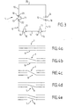
- la figure 1 décrit, en perspective, un exemple de réalisation du dispositif d'aiguillage conforme à l'invention, équipant un exemple d'installation de transport dans laquelle il peut être utilisé.
- les figures 2a à 2c illustrent, en vue de dessous, la configuration de différentes faces du barillet constituant le dispositif d'aiguillage représenté à la figure 1,
- la figure 3 est une vue schématique en section, réalisée selon la ligne III-III représentée aux figures 2a à 2c précédentes,
- les figures 4a à 4e illustrent, de manière schématique, la configuration des différentes faces d'un barillet constituant un autre exemple de mise en oeuvre du dispositif d'aiguillage conforme à l'invention.
- Figure 1 describes, in perspective, an embodiment of the switching device according to the invention, equipping an example of a transport installation in which it can be used.
- FIGS. 2a to 2c illustrate, in bottom view, the configuration of different faces of the barrel constituting the switching device shown in FIG. 1,
- FIG. 3 is a diagrammatic view in section, produced along line III-III shown in the preceding FIGS. 2a to 2c,
- Figures 4a to 4 illustrate, schematically, the configuration of the different faces of a barrel constituting another example of implementation of the switching device according to the invention.
La présente invention concerne un dispositif d'aiguillage pour installation de transport d'objets tels que, notamment, bouteilles, flacons ou autres.The present invention relates to a switching device for installation for transporting objects such as, in particular, bottles, flasks or other.
Comme représenté à la figure 1, le dispositif d'aiguillage 1
conforme à l'invention est destiné à être placé sur la trajectoire des objets 2
que l'on souhaite transporter, l'installation correspondante comprenant, au
moins partiellement, plusieurs lignes 3, 4 de convoyage.As shown in Figure 1, the
Comme développé plus loin, il s'agit, notamment d'installations
de transport par jet d'air destinées, par exemple, à des objets 2 munis d'un
goulot 5. Dans de telles installations, lesdites lignes de convoyage 3, 4
comprennent, notamment, des rails supports 6 aptes à coopérer avec lesdits
objets 2 au niveau desdits goulots 5, et des chambres de soufflage 7, aptes à
permettre la projection d'un flux d'air sur lesdits objets 2 de manière à les
propulser.As further developed, these include installations
transport by air jet intended, for example, for objects 2 provided with a
neck 5. In such installations, said
Ledit dispositif d'aiguillage 1 permet le transfert, entre son
entrée et sa sortie, desdits objets 2 d'au moins une des lignes de convoyage à
une autre et/ou leur passage sans changement de ligne de convoyage.Said switching
Il peut ainsi être utilisé, comme les dispositifs d'aiguillage en Y classiques, avec deux lignes de convoyage en entrée et une en sortie, ou l'inverse. Grâce à sa structure, il peut également être utilisé avec plusieurs lignes de convoyage à la fois en entrée et en sortie. Par « plusieurs », il faut entendre naturellement « au moins deux ».It can thus be used, like Y-switch devices conventional, with two conveyor lines at the inlet and one at the outlet, or Conversely. Thanks to its structure, it can also be used with several conveyor lines for both input and output. By "several", it is necessary naturally hear "at least two".
Pour cela, selon l'invention, il est constitué d'un barillet 8 de
section polygonale, apte à pivoter autour de son axe longitudinal 9 de manière
à permettre le positionnement alternatif de chacune de ses faces latérales 10,
11, 12, dans le prolongement desdites lignes de convoyage 3, 4. Ledit barillet 8
présente donc une forme prismatique, chacune de ses faces latérales 10, 11,
12 étant munie, en outre, d'au moins une ligne de transfert 13 ; 14,15 ; 16
orientée selon une des alternatives possibles d'aiguillage desdits objets 2.For this, according to the invention, it consists of a
Par « alternative possible d'aiguillage », on entend que lesdites faces latérales présentent chacune au moins pour certaines d'entre elles 10,11, 12, une ou des lignes de transfert permettant une des orientations souhaitées des objets 2, à savoir, soit le passage sans changement de ligne de convoyage, et ceci pour l'ensemble des lignes de convoyage, soit le transfert d'une ligne de convoyage à une autre pour une ou plusieurs des lignes de convoyage, les objets 2 convoyés sur les éventuelles autres lignes ne voyant pas leur trajectoire modifiée.By "possible referral alternative" is meant that said side faces each have at least some of them 10,11, 12, one or more transfer lines allowing one of the desired orientations objects 2, namely, the passage without changing the line of conveyor, and this for all conveyor lines, i.e. transfer from one conveyor line to another for one or more of the conveying, objects 2 conveyed on any other lines not seeing not their modified trajectory.
On constate ainsi, chaque face remplissant une fonction
spécifique, que la trajectoire des objets 2 peut être optimisée dans chacune
des alternatives. En particulier, en cas de passage sans changement de ligne,
la traversée du dispositif d'aiguillage 1 peut se faire de manière rectiligne et
permet donc d'éviter des ruptures de rythme. We thus see, each face fulfilling a function
specific, that the trajectory of objects 2 can be optimized in each
alternatives. In particular, in the event of passage without changing the line,
the crossing of the
Selon le mode particulier de réalisation représenté, le barillet 8
présente quatre faces latérales. Toutefois, toute forme prismatique présentant
au moins trois faces latérales planes pourrait également être utilisée.According to the particular embodiment shown, the
Si l'on se reporte maintenant aux figures 2a à 2c, on constate
que sur les faces 10, 12 permettant le passage d'une ligne de convoyage 3, 4 à
une autre, les lignes de transfert 13, 16 présentent, éventuellement, au niveau
des changements de direction, un angle légèrement arrondi. Dans le cas des
faces 11 permettant un passage sans transfert de ligne de convoyage, les
lignes de transfert 14, 15 sont, par exemple, comme précédemment évoqué
dans le prolongement rectiligne desdites lignes de convoyage 3, 4.If we now refer to Figures 2a to 2c, we see
that on the
Lesdites faces 10, 12 permettant un changement de lignes de
convoyage pourront également présenter deux lignes de transfert, alors
prévues en Y, pour autoriser, en outre, un passage sans changement de ligne
pour l'une des lignes de convoyage 2, 3.Said faces 10, 12 allowing a change of lines of
conveying may also have two transfer lines, so
provided in Y, to authorize, in addition, a passage without line change
for one of the
L'axe longitudinal 9 dudit barillet 8 est, notamment, destiné à
être orienté sensiblement parallèlement aux lignes de convoyage 3, 4 et
comme illustré à la figure 1, se trouve au-dessus de ces dernières c'est-à-dire
du côté opposé à la trajectoire des objets 2.The
Chaque face latérale 10, 11, 12 présente, par exemple, une
dimension supérieure à l'entraxe prévu entre les lignes de convoyage 3, 4 en
entrée et/ou en sortie dudit dispositif d'aiguillage 1.Each
Selon l'exemple particulier de réalisation représenté, ledit
barillet 8 est prévu de section sensiblement carrée, une première 11 de ses
faces latérales permettant le passage sans changement de ligne de
convoyage, une seconde 12 permettant le passage d'une des files 4 de
convoyage, dite file droite, à l'autre file 3 de convoyage, dite file gauche, une
troisième 10 permettant le passage de ladite file gauche 3 à la dite file droite 4.According to the particular embodiment shown, said
Comme précédemment évoqué, ledit barillet 8 pourra
également présenter une section triangulaire, l'ensemble des possibilités
d'aiguillage étant alors également rempli dans le cas d'une installation
comprenant, comme représentée, deux lignes de convoyage 3, 4 en entrée et
en sortie dudit dispositif 1. Toutefois, une section quadrangulaire présente
l'avantage d'offrir une face supplémentaire pouvant être équipée en fonction de
la structure de l'installation dans laquelle ledit dispositif d'aiguillage 1 est inséré.As previously mentioned, said
Avec une section carrée, par rotation d'un quart de tour dudit
barillet 8 selon la flèche repérée 30, on change ainsi à volonté d'alternative
d'aiguillage des objets 2.With a square section, by rotation of a quarter turn of said
Ladite première face 11 se trouve, par exemple, entre lesdites
seconde et troisième faces 12, 10.Said
Ladite première face 11 présente, notamment, deux lignes de
transfert 14, 15, parallèles entre elles. Quant auxdites seconde 12 et troisième
10 faces latérales, elles présentent chacune une ligne de transfert 13, 16 reliant
les lignes de convoyage 3, 4 concernées selon une direction sensiblement
parallèle à la diagonale de la face latérale 10, 12 correspondante du barillet 8.Said
Si l'on se reporte maintenant à la figure 3, on constate que
chaque ligne de transfert 13 ; 14 , 15 ; 16 est constituée, par exemple d'un
canal 17 apte à accueillir une extrémité 5 desdits objets 2, et d'un rail support
18, prévu sous ledit canal 17, apte à coopérer avec ladite extrémité 5.If we now refer to Figure 3, we see that
each
Ledit dispositif d'aiguillage 1 comprend, en outre,
éventuellement, au moins au niveau desdites lignes de transfert 13 ; 14, 15 ; 16
des guides latéraux, non représentés. Ces derniers ont pour fonction,
notamment, d'améliorer le guidage des objets transportés. En cas d'utilisation,
ils donnent audit barillet 8, en quelque sorte l'aspect d'un hérisson.Said switching
Si l'on se reporte de nouveau à la figure 1, on constate que,
selon l'exemple particulier de réalisation représenté, ledit dispositif d'aiguillage
1 comprend, en amont et en aval dudit barillet 8, une chambre de circulation
19, 20 apte à favoriser l'interface entre ledit barillet 8 et lesdites lignes de
convoyage 3, 4, et ceci notamment en fonction de la structure de l'installation
utilisée.If we refer again to Figure 1, we see that,
according to the particular embodiment shown, said
Lesdites chambres de circulation 19, 20 et ledit barillet 8 sont,
par exemple, de même section et/ou dans le prolongement les uns des autres
lorsque ledit barillet 8 est en position, lesdites chambres de circulation 19, 20
étant prévues fixes, c'est-à-dire ne tournant pas contrairement audit barillet 8.Said
Lesdites chambres de circulation 19, 20, sont naturellement
munies de lignes de convoyage des objets 2, notamment dans le prolongement
rectiligne desdites lignes de convoyage 3, 4 de l'installation dans laquelle ledit
dispositif 1 est inséré. Comme pour les lignes de transfert 13; 14, 15 ; 16, elles
présentent, par exemple, une structure formée d'un canal et d'un rail support .Said
Lesdites chambres de circulation 19, 20 pourront en outre,
éventuellement, être elles aussi munies de guides latéraux des objets 2.Said
Cela étant, ledit dispositif d'aiguillage 1 est muni, par exemple,
d'un moteur électrique, non représenté, apte à entraíner ledit barillet 8 en
rotation.However, said switching
En se reportant aux figures 4a à 4e, on constate, comme précédemment évoqué, que le dispositif d'aiguillage conforme à l'invention peut également être muni de plus de deux lignes de convoyage en entrée et en sortie. Ici, il s'agit d'une installation comportant trois lignes de convoyage en entrée et en sortie.Referring to FIGS. 4a to 4e, it can be seen, as previously mentioned, that the switching device according to the invention can also have more than two conveyor lines at the inlet and exit. Here, it is an installation comprising three conveying lines in input and output.
Dans le cas illustré, le barillet 8 comprend, par exemple, cinq
faces latérales de manière à permettre l'ensemble des alternatives possibles
d'aiguillage vers la droite.In the illustrated case, the
L'invention concerne également une installation de transport
par jet d'air d'objets 2 tels que, notamment, bouteilles, flacons ou autres,
équipée d'un dispositif d'aiguillage 1 tel que présenté ci-dessus.The invention also relates to a transport installation
by air jet of objects 2 such as, in particular, bottles, flasks or the like,
equipped with a
Comme représenté à la figure 1 et comme précédemment
évoqué, il s'agit, par exemple, d'une installation comprenant des rails supports
6, aptes à coopérer avec lesdits objets 2 le long de ses lignes de convoyage 3,
4, et des chambres de soufflage 7 aptes à permettre la projection d'un flux d'air
sur lesdits objets 2 de manière à les propulser le long desdites lignes de
convoyage 3, 4.As shown in Figure 1 and as before
mentioned, for example, an installation comprising support rails
6, able to cooperate with said objects 2 along its
Selon l'exemple particulier de réalisation illustré, lesdites
chambres de souffage 7 sont disposées au-dessus desdits rails supports 6. De
plus, lesdites chambres de soufflage 7 présentent des canaux 21 dans lesquels
une extrémité 5 desdits objets 2 peut circuler sous l'action de jet d'air provenant
desdites chambres de soufflage 7 à travers des fentes, non représentées,
réalisées sur les parois desdits canaux 17. Dans ce cas, lesdits rails supports 6
se trouvent sous lesdits canaux 21 et sont constitués, notamment, de deux
rampes 22, 23 se trouvant de chaque côté desdits canaux 21 correspondant.According to the particular exemplary embodiment illustrated, said
blowing
De telles installations peuvent être utilisées pour transporter
des objets 2 présentant, par exemple, une excroissance 24 au niveau de leur
goulot 5, ledit goulot 5 circulant dans ledit canal 21 et ladite excroissance 24
coopérant avec lesdites rampes 22, 23.Such facilities can be used to transport
objects 2 having, for example, a
Cela étant, selon un tel exemple de mise en oeuvre, les rails
supports 6, 18 de ladite installation et dudit dispositif d'aiguillage 1 sont prévus
dans le prolongement les uns des autres ainsi que lesdits canaux 21, 17. De
plus, lesdits canaux 17 du dispositif d'aiguillage 1 sont munis, éventuellement,
de fentes permettant la propulsion des jets d'air sur les objets 2 tandis que
lesdits rails supports 18 dudit dispositif d'aiguillage 1 sont constitués de deux
rampes prévues de chaque côté desdits canaux 17, et ceci aussi bien pour ledit
barillet que, le cas échéant, pour lesdites chambres de circulation 19, 20.However, according to such an example of implementation, the rails
supports 6, 18 of said installation and of said
L'intégration dudit dispositif d'aiguillage 1 dans l'installation de
transport par jet d'air décrite est ainsi optimisée. A ce sujet, il est à noter que,
dans ce cas, lesdites chambres de circulation 19, 20, sont particulièrement
utiles. En effet, elles favorisent une jonction étanche entre lesdites chambres
de soufflage 7 des lignes de convoyage 3, 4 et ledit barillet 8. Le transport des
objets 2 lors de l'aiguillage est ainsi favorisé avec un minimum de déperdition
d'air.The integration of said
Si une augmentation de pression dans ledit barillet 8 était
toutefois nécessaire, une soufflerie, non représentée, pourrait être prévue, par
exemple sur une face libre 25 dudit barillet 8.If an increase in pressure in said
Toutefois, ladite face 25 peut, selon un autre mode de
réalisation, présenter des lignes de transfert, selon une des alternatives
possibles d'aiguillage, éventuellement redondante par rapport aux alternatives
déjà présentes sur les autres faces 10, 11, 12. However, said
Toujours pour favoriser le transport des objets 2, des guides latéraux non représentés, peuvent également être prévus le long des lignes de convoyage 3, 4 de ladite installation.Always to promote the transport of objects 2, guides side not shown, can also be provided along the lines of conveying 3, 4 of said installation.
Naturellement, d'autres modes de mise en oeuvre de la présente invention à la portée de l'homme de l'art auraient pu être envisagés sans pour autant sortir du cadre de l'invention.Naturally, other modes of implementing the present invention within the reach of ordinary skill in the art could have been contemplated without departing from the scope of the invention.
Claims (10)
- Switching device (1) for an installation for conveying objects (2) such as, in particular, bottles, flasks or the like, including, at least partially, several lines (3, 4) for conveying said objects (2), said switching device (1), intended to be placed on the path of said objects (2), being capable of enabling them to be transferred, between the input and the output of said device (1), from at least one of the conveying lines to another and/or of enabling them to pass on without changing conveying lines, characterised by the fact that it is constituted by a barrel (8) having a polygonal cross-section, capable of pivoting about its longitudinal axis (9) so as to permit the alternative positioning of each of its lateral faces (10, 11, 12) in the continuation of said conveying lines (3, 4), each of said side faces (10, 11, 12) being provided with at least one transfer line (13; 14, 15; 16) orientated according to one of the possible alternatives for switching said objects (2).
- Device according to claim 1, in which the longitudinal axis (9) of the barrel (8) is designed to be orientated substantially parallel to the conveying lines (3, 4).
- Device according to claim 1, in which the longitudinal axis (9) of said barrel (8) is designed to be located above said conveying lines (3, 4).
- Device according to claim 1, in which each lateral face (10, 11, 12) has a dimension greater than the distance between centres provided between the conveying lines (3, 4) at the input and/or the output.
- Device according to claim 1, in which said barrel (8) is designed to be of a substantially square cross-section, with a first (11) of its lateral faces permitting passage without changing conveying lines, a second (12) permitting passage from one (4) of the conveying lines, or so-called righthand line, to the other (3) conveying line, or so-called left-hand line, and a third one (10) permitting passage from said left-hand line (3) to said righthand line (4).
- Device according to claim 5, in which said first face (11) has two transfer lines (14, 15) parallel to one another and/or in the rectilinear continuation of each of the corresponding conveying lines (3, 4) and/or said second (12) and third (10) lateral faces each has a transfer line (13, 16) connecting the conveying lines (3, 4) concerned in a direction substantially parallel to the diagonal of the corresponding lateral face (12, 10) of said barrel (8).
- Device according to claim 1, in which each transfer line (13; 14, 15; 16) is constituted by a channel (17), capable of receiving one end (5) of said objects (2), and by a support rail (18) provided under said channel (17), capable of co-operating with said end (5).
- Device according to claim 1, further including, at least in the area of said transfer lines (13; 14, 15; 16), lateral guides.
- Device according to claim 1, including, upstream and downstream of said barrel (8), a travel chamber (19, 20) capable of facilitating the interface between said barrel (8) and said conveying lines (3, 4).
- Installation for conveying by air jet objects (2) such as bottles, flasks or the like, equipped with a switching device according to claim 1.
Applications Claiming Priority (3)
| Application Number | Priority Date | Filing Date | Title |
|---|---|---|---|
| FR9704514A FR2761671B1 (en) | 1997-04-08 | 1997-04-08 | REFERRING DEVICE FOR A DEVICE FOR TRANSPORTING OBJECTS SUCH AS, IN PARTICULAR, BOTTLES, BOTTLES OR THE LIKE AND AIR JET TRANSPORTATION DEVICE PROVIDED WITH SUCH A DEVICE |
| FR9704514 | 1997-04-08 | ||
| PCT/FR1998/000716 WO1998045196A1 (en) | 1997-04-08 | 1998-04-08 | Switching device for conveyor system installation |
Publications (2)
| Publication Number | Publication Date |
|---|---|
| EP0973683A1 EP0973683A1 (en) | 2000-01-26 |
| EP0973683B1 true EP0973683B1 (en) | 2002-02-20 |
Family
ID=9505831
Family Applications (1)
| Application Number | Title | Priority Date | Filing Date |
|---|---|---|---|
| EP98920594A Expired - Lifetime EP0973683B1 (en) | 1997-04-08 | 1998-04-08 | Switching device for conveyor system installation |
Country Status (12)
| Country | Link |
|---|---|
| US (1) | US6257805B1 (en) |
| EP (1) | EP0973683B1 (en) |
| JP (1) | JP2001518864A (en) |
| KR (1) | KR100339058B1 (en) |
| CN (1) | CN1097012C (en) |
| AT (1) | ATE213484T1 (en) |
| AU (1) | AU737476B2 (en) |
| BR (1) | BR9807923A (en) |
| CA (1) | CA2284875C (en) |
| DE (1) | DE69803921T2 (en) |
| FR (1) | FR2761671B1 (en) |
| WO (1) | WO1998045196A1 (en) |
Families Citing this family (6)
| Publication number | Priority date | Publication date | Assignee | Title |
|---|---|---|---|---|
| FR2824544B1 (en) * | 2001-05-09 | 2003-10-10 | Netra Systems | DUAL TRANSLATION AND ROTATION MOVEMENT FOR AIR JET CONVEYOR |
| DE10162827A1 (en) * | 2001-12-20 | 2003-10-02 | Krones Ag | Switch device for air conveyors |
| MX2008016053A (en) * | 2006-06-13 | 2009-06-05 | Arrowhead Conveyor Corp Inc | Conveyor apparatus. |
| DE102007023219A1 (en) * | 2007-05-18 | 2008-11-20 | Siemens Ag | Aircraft baggage-conveyor system, has guide rails corresponding to one of guiding channels of cylinder in effective position, where guide rails run before and after deflector in transporting direction |
| US7997405B2 (en) | 2009-07-22 | 2011-08-16 | Arrowhead Systems, Inc. | Sanitary conveyor |
| WO2015024936A1 (en) * | 2013-08-23 | 2015-02-26 | Siemens Aktiengesellschaft | Switching arrangement for a cargo-conveying system |
Family Cites Families (3)
| Publication number | Priority date | Publication date | Assignee | Title |
|---|---|---|---|---|
| FR886656A (en) * | 1942-06-06 | 1943-10-21 | Lamson Ets | Further training in pneumatic line equipment |
| US5100265A (en) * | 1991-01-22 | 1992-03-31 | Jetstream Systems, Inc. | Rotatable changeover parts for conveyor system |
| ATE135323T1 (en) * | 1993-10-22 | 1996-03-15 | Neu Trans System Sa | ROTARY TABLE SWITCH FOR A PNEUMATIC CONVEYING DEVICE OF CONTAINERS |
-
1997
- 1997-04-08 FR FR9704514A patent/FR2761671B1/en not_active Expired - Fee Related
-
1998
- 1998-04-08 DE DE69803921T patent/DE69803921T2/en not_active Expired - Fee Related
- 1998-04-08 EP EP98920594A patent/EP0973683B1/en not_active Expired - Lifetime
- 1998-04-08 JP JP54246598A patent/JP2001518864A/en active Pending
- 1998-04-08 KR KR1019997008650A patent/KR100339058B1/en not_active IP Right Cessation
- 1998-04-08 AT AT98920594T patent/ATE213484T1/en not_active IP Right Cessation
- 1998-04-08 WO PCT/FR1998/000716 patent/WO1998045196A1/en active IP Right Grant
- 1998-04-08 AU AU73401/98A patent/AU737476B2/en not_active Ceased
- 1998-04-08 CA CA002284875A patent/CA2284875C/en not_active Expired - Fee Related
- 1998-04-08 CN CN98804004A patent/CN1097012C/en not_active Expired - Fee Related
- 1998-04-08 US US09/402,718 patent/US6257805B1/en not_active Expired - Fee Related
- 1998-04-08 BR BR9807923-9A patent/BR9807923A/en active Search and Examination
Also Published As
| Publication number | Publication date |
|---|---|
| JP2001518864A (en) | 2001-10-16 |
| EP0973683A1 (en) | 2000-01-26 |
| KR100339058B1 (en) | 2002-05-31 |
| FR2761671B1 (en) | 1999-06-11 |
| WO1998045196A1 (en) | 1998-10-15 |
| CN1097012C (en) | 2002-12-25 |
| BR9807923A (en) | 2000-02-22 |
| CA2284875C (en) | 2003-07-01 |
| DE69803921T2 (en) | 2003-01-16 |
| ATE213484T1 (en) | 2002-03-15 |
| AU7340198A (en) | 1998-10-30 |
| CN1252036A (en) | 2000-05-03 |
| US6257805B1 (en) | 2001-07-10 |
| DE69803921D1 (en) | 2002-03-28 |
| AU737476B2 (en) | 2001-08-23 |
| CA2284875A1 (en) | 1998-10-15 |
| FR2761671A1 (en) | 1998-10-09 |
| KR20010005587A (en) | 2001-01-15 |
Similar Documents
| Publication | Publication Date | Title |
|---|---|---|
| EP0973683B1 (en) | Switching device for conveyor system installation | |
| CA2693091C (en) | Cable-carrying chain for an aircraft wing leading edge mobile flap shutter | |
| WO2014049082A1 (en) | Light guide for a motor vehicle lighting and/or signalling device | |
| EP0466605B1 (en) | Reflector for a lighting device of an automotive vehicle, and headlight and signal light incorporating such a reflector | |
| CA2707670A1 (en) | Optimized layout of an aircraft cabin | |
| FR2890151A1 (en) | Headlamp for vehicle, has reflecting face of addition reflector divided into multiple reflecting portions, where surface shape of each reflecting portion is formed into ellipsoid of revolution in vertical direction | |
| EP0947761A1 (en) | Signaling light with several light sources | |
| EP1577213A1 (en) | Arrangement of seats for aircraft cabin | |
| CA2610831A1 (en) | Medical unit for an aircraft cabin associated with a berth | |
| EP1568607A1 (en) | Arrangement of seats for aircraft cabin | |
| FR2925919A1 (en) | DEVICE FOR BLOWING GAS ON A FACE OF A THREADED STRIP MATERIAL | |
| FR3030684A1 (en) | LUMINOUS DEVICE COMPRISING SURFACE SOURCES OF LIGHT | |
| EP1739468B1 (en) | Lighting or signalling device for an automobile | |
| EP3398885B1 (en) | Object sorting system for logistics platform | |
| FR2985300A1 (en) | PROTECTIVE DEVICE PROVIDING AT LEAST ONE LIGHT TRANSFER LIGHTING FUNCTION USING DEFINED STIFFEN (S) IN A TRANSPARENT WALL | |
| EP3238992B1 (en) | Rotary light module | |
| EP1089904B1 (en) | Chair lift with improved boarding | |
| WO2001051391A1 (en) | Method and device for conveying objects in a suspended position | |
| FR2468499A1 (en) | PROPULSIVE SYSTEM FOR A PROPELLER SHIP, AND SHIP THUS EQUIPPED | |
| FR2753784A1 (en) | AMMUNITION SUPPLY DEVICE FOR AN AIRCRAFT-MOUNTED WEAPON, EQUIPPED WITH SUCH A DEVICE | |
| CA2324891A1 (en) | Device for conveying objects by blowing and element defining at least said device blowing chamber | |
| EP0357529A1 (en) | No-pressure aligner for different items,in particular for bottles | |
| EP1472132B1 (en) | Structure for motor vehicle and vehicle equipped with same | |
| EP2712747B1 (en) | Luftausströmer gestaltet zur Verhinderung des Durchgangs von kleinen Objekten | |
| FR2665424A1 (en) | Device for channelling without pressure for containers |
Legal Events
| Date | Code | Title | Description |
|---|---|---|---|
| PUAI | Public reference made under article 153(3) epc to a published international application that has entered the european phase |
Free format text: ORIGINAL CODE: 0009012 |
|
| 17P | Request for examination filed |
Effective date: 19990913 |
|
| AK | Designated contracting states |
Kind code of ref document: A1 Designated state(s): AT BE CH CY DE DK ES FI FR GB GR IE IT LI LU MC NL PT SE |
|
| GRAG | Despatch of communication of intention to grant |
Free format text: ORIGINAL CODE: EPIDOS AGRA |
|
| 17Q | First examination report despatched |
Effective date: 20010425 |
|
| GRAG | Despatch of communication of intention to grant |
Free format text: ORIGINAL CODE: EPIDOS AGRA |
|
| GRAH | Despatch of communication of intention to grant a patent |
Free format text: ORIGINAL CODE: EPIDOS IGRA |
|
| GRAH | Despatch of communication of intention to grant a patent |
Free format text: ORIGINAL CODE: EPIDOS IGRA |
|
| REG | Reference to a national code |
Ref country code: GB Ref legal event code: IF02 |
|
| GRAA | (expected) grant |
Free format text: ORIGINAL CODE: 0009210 |
|
| AK | Designated contracting states |
Kind code of ref document: B1 Designated state(s): AT BE CH CY DE DK ES FI FR GB GR IE IT LI LU MC NL PT SE |
|
| PG25 | Lapsed in a contracting state [announced via postgrant information from national office to epo] |
Ref country code: NL Free format text: LAPSE BECAUSE OF FAILURE TO SUBMIT A TRANSLATION OF THE DESCRIPTION OR TO PAY THE FEE WITHIN THE PRESCRIBED TIME-LIMIT Effective date: 20020220 Ref country code: IE Free format text: LAPSE BECAUSE OF FAILURE TO SUBMIT A TRANSLATION OF THE DESCRIPTION OR TO PAY THE FEE WITHIN THE PRESCRIBED TIME-LIMIT Effective date: 20020220 Ref country code: GR Free format text: LAPSE BECAUSE OF FAILURE TO SUBMIT A TRANSLATION OF THE DESCRIPTION OR TO PAY THE FEE WITHIN THE PRESCRIBED TIME-LIMIT Effective date: 20020220 Ref country code: GB Free format text: LAPSE BECAUSE OF FAILURE TO SUBMIT A TRANSLATION OF THE DESCRIPTION OR TO PAY THE FEE WITHIN THE PRESCRIBED TIME-LIMIT Effective date: 20020220 Ref country code: FI Free format text: LAPSE BECAUSE OF FAILURE TO SUBMIT A TRANSLATION OF THE DESCRIPTION OR TO PAY THE FEE WITHIN THE PRESCRIBED TIME-LIMIT Effective date: 20020220 Ref country code: AT Free format text: LAPSE BECAUSE OF FAILURE TO SUBMIT A TRANSLATION OF THE DESCRIPTION OR TO PAY THE FEE WITHIN THE PRESCRIBED TIME-LIMIT Effective date: 20020220 |
|
| REF | Corresponds to: |
Ref document number: 213484 Country of ref document: AT Date of ref document: 20020315 Kind code of ref document: T |
|
| REG | Reference to a national code |
Ref country code: CH Ref legal event code: EP |
|
| REF | Corresponds to: |
Ref document number: 69803921 Country of ref document: DE Date of ref document: 20020328 |
|
| PG25 | Lapsed in a contracting state [announced via postgrant information from national office to epo] |
Ref country code: MC Free format text: LAPSE BECAUSE OF NON-PAYMENT OF DUE FEES Effective date: 20020408 Ref country code: LU Free format text: LAPSE BECAUSE OF NON-PAYMENT OF DUE FEES Effective date: 20020408 |
|
| PG25 | Lapsed in a contracting state [announced via postgrant information from national office to epo] |
Ref country code: CY Free format text: LAPSE BECAUSE OF FAILURE TO SUBMIT A TRANSLATION OF THE DESCRIPTION OR TO PAY THE FEE WITHIN THE PRESCRIBED TIME-LIMIT Effective date: 20020430 Ref country code: BE Free format text: LAPSE BECAUSE OF NON-PAYMENT OF DUE FEES Effective date: 20020430 |
|
| PG25 | Lapsed in a contracting state [announced via postgrant information from national office to epo] |
Ref country code: PT Free format text: LAPSE BECAUSE OF FAILURE TO SUBMIT A TRANSLATION OF THE DESCRIPTION OR TO PAY THE FEE WITHIN THE PRESCRIBED TIME-LIMIT Effective date: 20020520 Ref country code: DK Free format text: LAPSE BECAUSE OF FAILURE TO SUBMIT A TRANSLATION OF THE DESCRIPTION OR TO PAY THE FEE WITHIN THE PRESCRIBED TIME-LIMIT Effective date: 20020520 |
|
| NLV1 | Nl: lapsed or annulled due to failure to fulfill the requirements of art. 29p and 29m of the patents act | ||
| GBV | Gb: ep patent (uk) treated as always having been void in accordance with gb section 77(7)/1977 [no translation filed] |
Effective date: 20020220 |
|
| PG25 | Lapsed in a contracting state [announced via postgrant information from national office to epo] |
Ref country code: ES Free format text: LAPSE BECAUSE OF FAILURE TO SUBMIT A TRANSLATION OF THE DESCRIPTION OR TO PAY THE FEE WITHIN THE PRESCRIBED TIME-LIMIT Effective date: 20020829 |
|
| REG | Reference to a national code |
Ref country code: CH Ref legal event code: NV Representative=s name: ISLER & PEDRAZZINI AG |
|
| REG | Reference to a national code |
Ref country code: IE Ref legal event code: FD4D |
|
| PLBE | No opposition filed within time limit |
Free format text: ORIGINAL CODE: 0009261 |
|
| STAA | Information on the status of an ep patent application or granted ep patent |
Free format text: STATUS: NO OPPOSITION FILED WITHIN TIME LIMIT |
|
| 26N | No opposition filed |
Effective date: 20021121 |
|
| PGFP | Annual fee paid to national office [announced via postgrant information from national office to epo] |
Ref country code: FR Payment date: 20040427 Year of fee payment: 7 |
|
| PGFP | Annual fee paid to national office [announced via postgrant information from national office to epo] |
Ref country code: CH Payment date: 20050323 Year of fee payment: 8 Ref country code: SE Payment date: 20050323 Year of fee payment: 8 |
|
| PGFP | Annual fee paid to national office [announced via postgrant information from national office to epo] |
Ref country code: DE Payment date: 20050401 Year of fee payment: 8 |
|
| PG25 | Lapsed in a contracting state [announced via postgrant information from national office to epo] |
Ref country code: FR Free format text: LAPSE BECAUSE OF NON-PAYMENT OF DUE FEES Effective date: 20051230 |
|
| REG | Reference to a national code |
Ref country code: FR Ref legal event code: ST Effective date: 20051230 |
|
| PG25 | Lapsed in a contracting state [announced via postgrant information from national office to epo] |
Ref country code: SE Free format text: LAPSE BECAUSE OF NON-PAYMENT OF DUE FEES Effective date: 20060409 |
|
| PG25 | Lapsed in a contracting state [announced via postgrant information from national office to epo] |
Ref country code: LI Free format text: LAPSE BECAUSE OF NON-PAYMENT OF DUE FEES Effective date: 20060430 Ref country code: CH Free format text: LAPSE BECAUSE OF NON-PAYMENT OF DUE FEES Effective date: 20060430 |
|
| PGFP | Annual fee paid to national office [announced via postgrant information from national office to epo] |
Ref country code: IT Payment date: 20060430 Year of fee payment: 9 |
|
| PG25 | Lapsed in a contracting state [announced via postgrant information from national office to epo] |
Ref country code: DE Free format text: LAPSE BECAUSE OF NON-PAYMENT OF DUE FEES Effective date: 20061101 |
|
| REG | Reference to a national code |
Ref country code: CH Ref legal event code: PL |
|
| EUG | Se: european patent has lapsed | ||
| PG25 | Lapsed in a contracting state [announced via postgrant information from national office to epo] |
Ref country code: IT Free format text: LAPSE BECAUSE OF NON-PAYMENT OF DUE FEES Effective date: 20070408 |